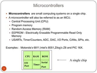
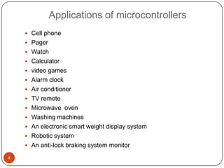
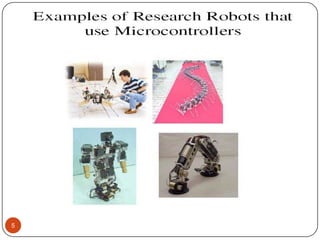
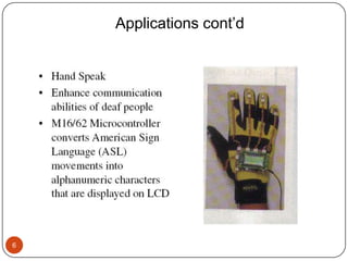
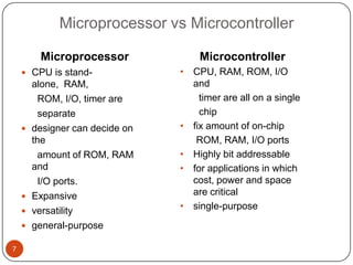
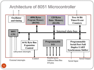
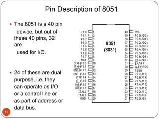
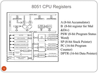
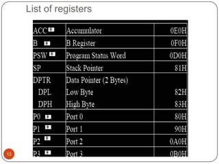
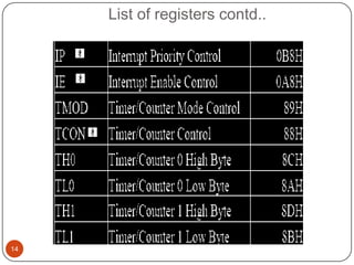
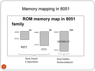
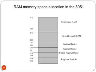
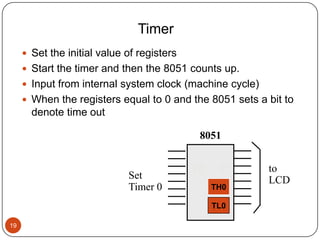
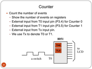
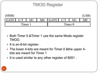
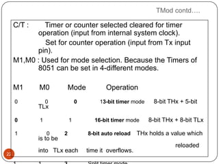
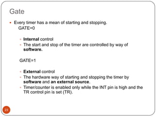
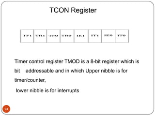
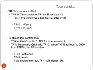
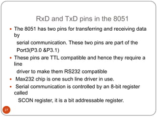
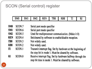
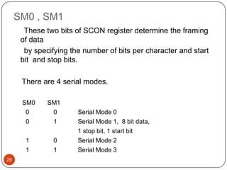
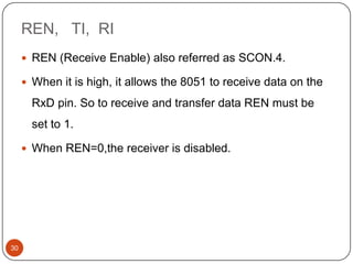
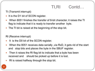
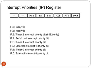
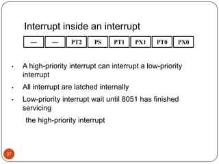
8051 Microcontroller Features and
             its Applications


1
Contents
     Microcontrollers
     Applications of microcontrollers
     Microprocessor vs microcontrollers
     History of 8051 microcontroller
     Features of microcontroller
     Block diagram and pin description of 8051
     Registers
     Memory mapping in 8051
     Timers and counters
     Serial communication
     Interrupts
     Applications of 8051 microcontroller
2
Microcontrollers
     Microcontrollers are small computing systems on a single chip.
     A microcontroller will also be referred to as an MCU.
       Central Processing Unit (CPU)
       Program memory
       Random Access Memory (RAM)
       EEPROM - Electrically Erasable Programmable Read Only
        Memory
       USARTs, Timer/Counters, ADC, DAC, I/O Ports, CANs, SPIs, etc.


    Examples : Motorola’s 6811,Intel’s 8051,Zilog’s Z8 and PIC 16X.


                    CPU    RAM     ROM
                                                          A single chip
                   I/O             Serial
                           Timer
                   Port            Port
3
Applications of microcontrollers
     Cell phone
     Pager
     Watch
     Calculator
     video games
     Alarm clock
     Air conditioner
     TV remote
     Microwave oven
     Washing machines
     An electronic smart weight display system
     Robotic system
     An anti-lock braking system monitor

4
5
Applications cont’d


6
Microprocessor vs Microcontroller

         Microprocessor              Microcontroller
     CPU is stand-              • CPU, RAM, ROM, I/O
        alone, RAM,                and
          ROM, I/O, timer are        timer are all on a single
          separate                   chip
       designer can decide on   • fix amount of on-chip
        the                         ROM, RAM, I/O ports
          amount of ROM, RAM     • Highly bit addressable
        and                      • for applications in which
          I/O ports.               cost, power and space
       Expansive                  are critical
       versatility              • single-purpose
       general-purpose

7
History of 8051 microcontroller

     In the year 1980 Intel corporation introduced an 8 bit
        microcontroller called 8051.
     It has 4K bytes of ROM,128 Bytes of RAM , a serial
      port, two
        16-bit Timers and 32 I/O pins.
     CPU can work with 8 bit of data at a time.
     Data larger than 8 bit can be broken into 8 bit pieces to
      be
        processed by the CPU


8
Important Features of 8051

     4K bytes ROM
     128 bytes RAM
     Four 8-bit I/O ports
     Two 8/16 bit timers
     Serial port
     64K external code memory space
     64K data memory space
     Multiple internal and external interrupt sources


9
Architecture of 8051 Microcontroller

      Oscillator             4096 Bytes         128 Bytes           Two 16 Bit
      and timing           Program Memory     Data Memory          Timer/Event
                                (ROM)            (RAM)               Counters


      8051                                            Internal data bus
      CPU


                    64 K Byte Bus           Programmable          Programmable
                      Expansion                  I/O              Serial Port Full
                       Control                                    Duplex UART
                                                                Synchronous Shifter
         subsystem interrupts


                                Control      Parallel ports                    Serial Output
     External interrupts                     Address Data Bus   Serial Input
                                             I/O pins
10
Pin Description of 8051

      The 8051 is a 40 pin
        device, but out of
       these 40 pins, 32
       are
        used for I/O.


      24 of these are dual
       purpose, i.e. they
       can operate as I/O
       or a control line or
       as part of address or
       data bus.
11
8051 CPU Registers


                  A (8-bit Accumulator)
                  B (8-bit register for Mul
                  &Div)
                  PSW (8-bit Program Status
                  Word)
                  SP (8-bit Stack Pointer)
                  PC (16-bit Program
                  Counter)
                  DPTR (16-bit Data Pointer)


12
List of registers


13
List of registers contd..


14
Memory mapping in 8051

          ROM memory map in 8051
     family
                     4k                  8k                32k
      0000H               0000H               0000H


      0FFFH

                                                 DS5000-32
                          1FFFH
              8051
                                  8752        7FFFH


                from Atmel                       from Dallas
                Corporation                      Semiconductor
15
RAM memory space allocation in the 8051

             7FH

                               Scratch pad RAM


              30H

             2FH
                                Bit-Addressable RAM
              20H
             1FH
              18H
                                 Register Bank 3
              17H
                                 Register Bank 2
             10H
              0FH            (Stack) Register Bank 1
              08H
              07H
                               Register Bank 0
              00H


16
Timers /Counters

     The 8051 has 2 timers/counters:

            Timer/Counter 0
            Timer/Counter 1


     Timer :

              Used as a time delay generator.
              Many microcontroller application requires the
               counting of external events such as
               frequency, time delay.

17
Registers Used in Timer/Counter
      8051 has two 16-bit Timer registers ,Timer 0 & Timer 1.

      As 8051 has 8-bit architecture , each Timer register is

       treated as two 8-bit registers namely
       TH0, TL0, TH1, TL1.

      One 8-bit mode register -TMOD.

      One 8-bit control register-TCON.


18
Timer
      Set the initial value of registers
      Start the timer and then the 8051 counts up.
      Input from internal system clock (machine cycle)
      When the registers equal to 0 and the 8051 sets a bit to
       denote time out

                                             8051


                                            P2    P1      to
                             Set                          LCD
                             Timer 0             TH0

                                                 TL0

19
Counter
      Count the number of events
       • Show the number of events on registers
       • External input from T0 input pin (P3.4) for Counter 0
       • External input from T1 input pin (P3.5) for Counter 1
       • External input from Tx input pin.
       • We use Tx to denote T0 or T1.
                                             8051

                                             TH0
                                                   P1     to
                                             TL0
                                                          LCD
                                          P3.4
                       a switch      T0
20
TMOD Register

 (MSB)                                                  (LSB)
  GATE      C/T    M1      M0    GATE     C/T    M1     M0
              Timer 1                       Timer 0


      Both Timer 0 &Timer 1 use the same Mode register
       TMOD.
      It is an-8-bit register .
      The lower 4-bits are meant for Timer 0 &the upper 4-
       bits are meant for Timer 1
      It is used similar to any other register of 8051 .


21
TMod contd….

     C/T :    Timer or counter selected cleared for timer
           operation (input from internal system clock).
              Set for counter operation (input from Tx input
           pin).
     M1,M0 : Used for mode selection. Because the Timers of
           8051 can be set in 4-different modes.

     M1      M0             Mode           Operation
     0           0              0        13-bit timer mode     8-bit THx + 5-bit
             TLx

     0       1              1          16-bit timer mode     8-bit THx + 8-bit TLx

     1           0      2           8-bit auto reload    THx holds a value which
             is to be
                                                                       reloaded
             into TLx each          time it overflows.
22
Gate
      Every timer has a mean of starting and stopping.
         GATE=0

           Internal control
           The start and stop of the timer are controlled by way of
            software.

          GATE=1

           External control
           The hardware way of starting and stopping the timer by
            software and an external source.
           Timer/counter is enabled only while the INT pin is high and the
            TR control pin is set (TR).


23
TCON Register


     Timer control register TMOD is a 8-bit register which is
     bit   addressable and in which Upper nibble is for
     timer/counter,

     lower nibble is for interrupts


24
Tcon contd…
      TR (Timer run control bit)
       • TR0 for Timer/counter 0; TR1 for Timer/counter 1.
        • TR is set by programmer to turn timer/counter on/off.


           TR=0 : off (stop)
           TR=1 : on (start)


      TF (timer flag, control flag)
        • TF0 for timer/counter 0; TF1 for timer/counter 1.
        • TF is like a carry. Originally, TF=0. When TH-TL roll over to 0000
          from FFFFH, the TF is set to 1.

           TF=0 : not reach
           TF=1: reach
           If we enable interrupt, TF=1 will trigger ISR.

25
8051- SERIAL COMMUNICATION


26
RxD and TxD pins in the 8051
      The 8051 has two pins for transferring and receiving data
       by
         serial communication. These two pins are part of the
         Port3(P3.0 &P3.1)
      These pins are TTL compatible and hence they require a
       line
         driver to make them RS232 compatible
      Max232 chip is one such line driver in use.
      Serial communication is controlled by an 8-bit register
       called
          SCON register, it is a bit addressable register.
27
SCON (Serial control) register


28
SM0 , SM1
       These two bits of SCON register determine the framing
      of data
       by specifying the number of bits per character and start
      bit and stop bits.

      There are 4 serial modes.

      SM0     SM1
       0       0       Serial Mode 0
       0       1       Serial Mode 1, 8 bit data,
                       1 stop bit, 1 start bit
       1        0      Serial Mode 2
       1        1      Serial Mode 3
29
REN, TI, RI
      REN (Receive Enable) also referred as SCON.4.

      When it is high, it allows the 8051 to receive data on the

       RxD pin. So to receive and transfer data REN must be
       set to 1.

      When REN=0,the receiver is disabled.


30
TI,RI           Contd…
     TI (Transmit interrupt)
      It is the D1 bit of SCON register.
         When 8051 finishes the transfer of 8-bit character, it raises the TI
         flag to indicate that it is ready to transfer another byte.
      The TI bit is raised at the beginning of the stop bit.


     RI (Receive interrupt)
        It is the D0 bit of the SCON register.
        When the 8051 receives data serially ,via RxD, it gets rid of the start
         and stop bits and places the byte in the SBUF register.
         Then it raises the RI flag bit to indicate that a byte has been
         received and should be picked up before it is lost.
        RI is raised halfway through the stop bit.

31
Interrupt Sources

     8051 has 6 sources of interrupts

       •   Reset
       •   Timer 0 overflow
       •   Timer 1 overflow
       •   External Interrupt 0
       •   External Interrupt 1
       •   Serial Port events (buffer full, buffer empty, etc)


32
Interrupt Enable Register


     •   Upon reset all Interrupts are disabled and do
         not
         respond to the Microcontroller
     •   These interrupts must be enabled by software in
         order for the Microcontroller to respond to them.
     •   This is done by an 8-bit register called Interrupt
         Enable Register (IE).


33
   EA    :     Global enable/disable.
        ---   :     Undefined.
        ET2   :     Enable Timer 2 interrupt.
        ES      :   Enable Serial port interrupt.
        ET1   :     Enable Timer 1 interrupt.
        EX1   :     Enable External 1 interrupt.
        ET0   :     Enable Timer 0 interrupt.
        EX0   :     Enable External 0 interrupt.


34
Interrupt Priorities
        If two interrupt sources interrupt at the same time ,the
           interrupt with the highest PRIORITY gets serviced first.

        All interrupts have a power on default priority order.
         1. External interrupt 0 (INT0)
         2. Timer interrupt0 (TF0)
         3. External interrupt 1 (INT1)
         4. Timer interrupt1 (TF1)
         5. Serial communication (RI+TI)


        Priority can also be set to “high” or “low” by IP reg.

35
Interrupt Priorities (IP) Register
         ---      ---    PT2       PS      PT1     PX1    PT0   PX0


       IP.7: reserved
       IP.6: reserved
       IP.5: Timer 2 interrupt priority bit (8052 only)
       IP.4: Serial port interrupt priority bit
       IP.3: Timer 1 interrupt priority bit
       IP.2: External interrupt 1 priority bit
       IP.1: Timer 0 interrupt priority bit
       IP.0: External interrupt 0 priority bit


36
Interrupt inside an interrupt
           ---    ---    PT2     PS     PT1     PX1   PT0    PX0


     •   A high-priority interrupt can interrupt a low-priority
         interrupt
     •   All interrupt are latched internally
     •   Low-priority interrupt wait until 8051 has finished
         servicing
          the high-priority interrupt


37
Applications of 8051 microcontroller


     • Embedded system
     • Industrial
     • Computer networking
     • Power input to the 8051 is very simple and straight
       forward.
     • 8051 could be used in low-power applications.


38
Applications cont’d

     • The 8051 has been in use in a wide number of
      devices, mainly because it is easy to integrate into
      a project or build a device around.

     • Energy Management:
         Efficient metering systems help in controlling
          energy usage in
           homes and industrial applications.
         These metering systems are made capable by
          incorporating
            microcontrollers.
39
Applications cont’d
     Touch screens:
       A high number of microcontroller providers incorporate
        touch-sensing capabilities in their designs.
       Portable electronics such as cell phones, media
        players and gaming devices are examples of
        microcontroller-based touch screens.

     Automobiles:
       The 8051 finds wide acceptance in providing
        automobile solutions.
       They are widely used in hybrid vehicles to manage
        engine variants.
40
       Functions such as cruise control and anti-brake
        system have been made more efficient with the use of
Applications cont’d

     Medical Devices:
       Portable medical devices such as blood pressure
        and glucose
          monitors use microcontrollers will to display
        data, thus
          providing higher reliability in providing medical
        results.


41
Thank you


42

8051 microcontroller features

  • 1.
    8051 Microcontroller Featuresand its Applications 1
  • 2.
    Contents  Microcontrollers  Applications of microcontrollers  Microprocessor vs microcontrollers  History of 8051 microcontroller  Features of microcontroller  Block diagram and pin description of 8051  Registers  Memory mapping in 8051  Timers and counters  Serial communication  Interrupts  Applications of 8051 microcontroller 2
  • 3.
    Microcontrollers  Microcontrollers are small computing systems on a single chip.  A microcontroller will also be referred to as an MCU.  Central Processing Unit (CPU)  Program memory  Random Access Memory (RAM)  EEPROM - Electrically Erasable Programmable Read Only Memory  USARTs, Timer/Counters, ADC, DAC, I/O Ports, CANs, SPIs, etc. Examples : Motorola’s 6811,Intel’s 8051,Zilog’s Z8 and PIC 16X. CPU RAM ROM A single chip I/O Serial Timer Port Port 3
  • 4.
    Applications of microcontrollers  Cell phone  Pager  Watch  Calculator  video games  Alarm clock  Air conditioner  TV remote  Microwave oven  Washing machines  An electronic smart weight display system  Robotic system  An anti-lock braking system monitor 4
  • 5.
  • 6.
  • 7.
    Microprocessor vs Microcontroller Microprocessor Microcontroller  CPU is stand- • CPU, RAM, ROM, I/O alone, RAM, and ROM, I/O, timer are timer are all on a single separate chip  designer can decide on • fix amount of on-chip the ROM, RAM, I/O ports amount of ROM, RAM • Highly bit addressable and • for applications in which I/O ports. cost, power and space  Expansive are critical  versatility • single-purpose  general-purpose 7
  • 8.
    History of 8051microcontroller  In the year 1980 Intel corporation introduced an 8 bit microcontroller called 8051.  It has 4K bytes of ROM,128 Bytes of RAM , a serial port, two 16-bit Timers and 32 I/O pins.  CPU can work with 8 bit of data at a time.  Data larger than 8 bit can be broken into 8 bit pieces to be processed by the CPU 8
  • 9.
    Important Features of8051  4K bytes ROM  128 bytes RAM  Four 8-bit I/O ports  Two 8/16 bit timers  Serial port  64K external code memory space  64K data memory space  Multiple internal and external interrupt sources 9
  • 10.
    Architecture of 8051Microcontroller Oscillator 4096 Bytes 128 Bytes Two 16 Bit and timing Program Memory Data Memory Timer/Event (ROM) (RAM) Counters 8051 Internal data bus CPU 64 K Byte Bus Programmable Programmable Expansion I/O Serial Port Full Control Duplex UART Synchronous Shifter subsystem interrupts Control Parallel ports Serial Output External interrupts Address Data Bus Serial Input I/O pins 10
  • 11.
    Pin Description of8051  The 8051 is a 40 pin device, but out of these 40 pins, 32 are used for I/O.  24 of these are dual purpose, i.e. they can operate as I/O or a control line or as part of address or data bus. 11
  • 12.
    8051 CPU Registers A (8-bit Accumulator) B (8-bit register for Mul &Div) PSW (8-bit Program Status Word) SP (8-bit Stack Pointer) PC (16-bit Program Counter) DPTR (16-bit Data Pointer) 12
  • 13.
  • 14.
  • 15.
    Memory mapping in8051 ROM memory map in 8051 family 4k 8k 32k 0000H 0000H 0000H 0FFFH DS5000-32 1FFFH 8051 8752 7FFFH from Atmel from Dallas Corporation Semiconductor 15
  • 16.
    RAM memory spaceallocation in the 8051 7FH Scratch pad RAM 30H 2FH Bit-Addressable RAM 20H 1FH 18H Register Bank 3 17H Register Bank 2 10H 0FH (Stack) Register Bank 1 08H 07H Register Bank 0 00H 16
  • 17.
    Timers /Counters The 8051 has 2 timers/counters:  Timer/Counter 0  Timer/Counter 1 Timer :  Used as a time delay generator.  Many microcontroller application requires the counting of external events such as frequency, time delay. 17
  • 18.
    Registers Used inTimer/Counter  8051 has two 16-bit Timer registers ,Timer 0 & Timer 1.  As 8051 has 8-bit architecture , each Timer register is treated as two 8-bit registers namely TH0, TL0, TH1, TL1.  One 8-bit mode register -TMOD.  One 8-bit control register-TCON. 18
  • 19.
    Timer  Set the initial value of registers  Start the timer and then the 8051 counts up.  Input from internal system clock (machine cycle)  When the registers equal to 0 and the 8051 sets a bit to denote time out 8051 P2 P1 to Set LCD Timer 0 TH0 TL0 19
  • 20.
    Counter  Count the number of events • Show the number of events on registers • External input from T0 input pin (P3.4) for Counter 0 • External input from T1 input pin (P3.5) for Counter 1 • External input from Tx input pin. • We use Tx to denote T0 or T1. 8051 TH0 P1 to TL0 LCD P3.4 a switch T0 20
  • 21.
    TMOD Register (MSB) (LSB) GATE C/T M1 M0 GATE C/T M1 M0 Timer 1 Timer 0  Both Timer 0 &Timer 1 use the same Mode register TMOD.  It is an-8-bit register .  The lower 4-bits are meant for Timer 0 &the upper 4- bits are meant for Timer 1  It is used similar to any other register of 8051 . 21
  • 22.
    TMod contd…. C/T : Timer or counter selected cleared for timer operation (input from internal system clock). Set for counter operation (input from Tx input pin). M1,M0 : Used for mode selection. Because the Timers of 8051 can be set in 4-different modes. M1 M0 Mode Operation 0 0 0 13-bit timer mode 8-bit THx + 5-bit TLx 0 1 1 16-bit timer mode 8-bit THx + 8-bit TLx 1 0 2 8-bit auto reload THx holds a value which is to be reloaded into TLx each time it overflows. 22
  • 23.
    Gate  Every timer has a mean of starting and stopping. GATE=0  Internal control  The start and stop of the timer are controlled by way of software. GATE=1  External control  The hardware way of starting and stopping the timer by software and an external source.  Timer/counter is enabled only while the INT pin is high and the TR control pin is set (TR). 23
  • 24.
    TCON Register Timer control register TMOD is a 8-bit register which is bit addressable and in which Upper nibble is for timer/counter, lower nibble is for interrupts 24
  • 25.
    Tcon contd…  TR (Timer run control bit) • TR0 for Timer/counter 0; TR1 for Timer/counter 1. • TR is set by programmer to turn timer/counter on/off.  TR=0 : off (stop)  TR=1 : on (start)  TF (timer flag, control flag) • TF0 for timer/counter 0; TF1 for timer/counter 1. • TF is like a carry. Originally, TF=0. When TH-TL roll over to 0000 from FFFFH, the TF is set to 1.  TF=0 : not reach  TF=1: reach  If we enable interrupt, TF=1 will trigger ISR. 25
  • 26.
  • 27.
    RxD and TxDpins in the 8051  The 8051 has two pins for transferring and receiving data by serial communication. These two pins are part of the Port3(P3.0 &P3.1)  These pins are TTL compatible and hence they require a line driver to make them RS232 compatible  Max232 chip is one such line driver in use.  Serial communication is controlled by an 8-bit register called SCON register, it is a bit addressable register. 27
  • 28.
  • 29.
    SM0 , SM1 These two bits of SCON register determine the framing of data by specifying the number of bits per character and start bit and stop bits. There are 4 serial modes. SM0 SM1 0 0 Serial Mode 0 0 1 Serial Mode 1, 8 bit data, 1 stop bit, 1 start bit 1 0 Serial Mode 2 1 1 Serial Mode 3 29
  • 30.
    REN, TI, RI  REN (Receive Enable) also referred as SCON.4.  When it is high, it allows the 8051 to receive data on the RxD pin. So to receive and transfer data REN must be set to 1.  When REN=0,the receiver is disabled. 30
  • 31.
    TI,RI Contd… TI (Transmit interrupt)  It is the D1 bit of SCON register.  When 8051 finishes the transfer of 8-bit character, it raises the TI flag to indicate that it is ready to transfer another byte.  The TI bit is raised at the beginning of the stop bit. RI (Receive interrupt)  It is the D0 bit of the SCON register.  When the 8051 receives data serially ,via RxD, it gets rid of the start and stop bits and places the byte in the SBUF register.  Then it raises the RI flag bit to indicate that a byte has been received and should be picked up before it is lost.  RI is raised halfway through the stop bit. 31
  • 32.
    Interrupt Sources 8051 has 6 sources of interrupts • Reset • Timer 0 overflow • Timer 1 overflow • External Interrupt 0 • External Interrupt 1 • Serial Port events (buffer full, buffer empty, etc) 32
  • 33.
    Interrupt Enable Register • Upon reset all Interrupts are disabled and do not respond to the Microcontroller • These interrupts must be enabled by software in order for the Microcontroller to respond to them. • This is done by an 8-bit register called Interrupt Enable Register (IE). 33
  • 34.
    EA : Global enable/disable.  --- : Undefined.  ET2 : Enable Timer 2 interrupt.  ES : Enable Serial port interrupt.  ET1 : Enable Timer 1 interrupt.  EX1 : Enable External 1 interrupt.  ET0 : Enable Timer 0 interrupt.  EX0 : Enable External 0 interrupt. 34
  • 35.
    Interrupt Priorities  If two interrupt sources interrupt at the same time ,the interrupt with the highest PRIORITY gets serviced first.  All interrupts have a power on default priority order. 1. External interrupt 0 (INT0) 2. Timer interrupt0 (TF0) 3. External interrupt 1 (INT1) 4. Timer interrupt1 (TF1) 5. Serial communication (RI+TI)  Priority can also be set to “high” or “low” by IP reg. 35
  • 36.
    Interrupt Priorities (IP)Register --- --- PT2 PS PT1 PX1 PT0 PX0 IP.7: reserved IP.6: reserved IP.5: Timer 2 interrupt priority bit (8052 only) IP.4: Serial port interrupt priority bit IP.3: Timer 1 interrupt priority bit IP.2: External interrupt 1 priority bit IP.1: Timer 0 interrupt priority bit IP.0: External interrupt 0 priority bit 36
  • 37.
    Interrupt inside aninterrupt --- --- PT2 PS PT1 PX1 PT0 PX0 • A high-priority interrupt can interrupt a low-priority interrupt • All interrupt are latched internally • Low-priority interrupt wait until 8051 has finished servicing the high-priority interrupt 37
  • 38.
    Applications of 8051microcontroller • Embedded system • Industrial • Computer networking • Power input to the 8051 is very simple and straight forward. • 8051 could be used in low-power applications. 38
  • 39.
    Applications cont’d • The 8051 has been in use in a wide number of devices, mainly because it is easy to integrate into a project or build a device around. • Energy Management:  Efficient metering systems help in controlling energy usage in homes and industrial applications.  These metering systems are made capable by incorporating microcontrollers. 39
  • 40.
    Applications cont’d Touch screens:  A high number of microcontroller providers incorporate touch-sensing capabilities in their designs.  Portable electronics such as cell phones, media players and gaming devices are examples of microcontroller-based touch screens. Automobiles:  The 8051 finds wide acceptance in providing automobile solutions.  They are widely used in hybrid vehicles to manage engine variants. 40  Functions such as cruise control and anti-brake system have been made more efficient with the use of
  • 41.
    Applications cont’d Medical Devices:  Portable medical devices such as blood pressure and glucose monitors use microcontrollers will to display data, thus providing higher reliability in providing medical results. 41
  • 42.