Downloaded 31 times


![Than we again set this register to outb(0x03,LCR); to assign the number of bits
to send and access receiver buffer, Transmitter holding register and interrupt
enable register.
5.2 DIVISOR LETCH- This register is used to set the baud rate for the
computer. It is a 16 bit register divided into two parts Divisor Letch (LS) and
Divisor Latch (MS) generally called as DLL and DLM. We can set baud rate
According to the given table below or we have a formula i.e.
output frequency of the Baud Generator is 16 x the Baud [divisor =
16 x (frequency input) / (baud rate c 16)].
Table:1
we put the value in init file for DLL and DLM like: outb(0x0c,DLL); and
(0x00,DLM);.
After this we put the value of LCR is (0x03,LCR); as discussed above.
5.3 Line Status Register (LSR) - This register provides status information to
the CPU concerning the data transfer. Its default value is 0110 0000.
we will set the bit 0 of this register because this bit is use to tell us that this bit
will be 1 whenever all the characters will be received and transfer to receiver
buffer register this bit will become 0 when all all the data has been read from](https://image.slidesharecdn.com/serialportdevicedriver-150320113509-conversion-gate01/85/Serial-Port-Device-Driver-9-320.jpg)


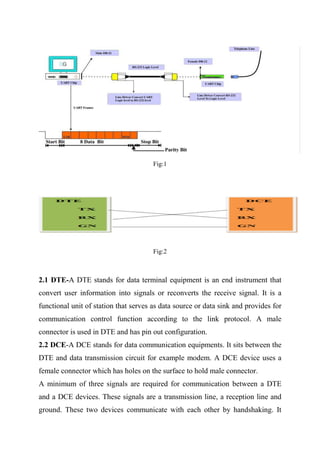
The document provides an overview of serial and parallel communication ports in PCs, detailing how they differ and their respective uses. It focuses on the RS232 protocol and the UART (Universal Asynchronous Receiver/Transmitter), explaining their roles in data transmission and the concept of handshaking between devices. Additionally, it includes technical specifications and register settings required for implementing serial communication through UART in computers.


![Introduction to ESP32 Programming [Road to RIoT 2017]](https://cdn.slidesharecdn.com/ss_thumbnails/roadtoriotsurabayagettingstartedesp32-170726155154-thumbnail.jpg?width=640&height=640&fit=bounds)