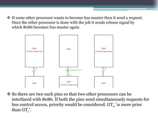
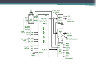
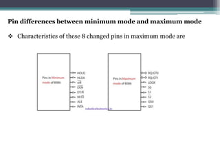
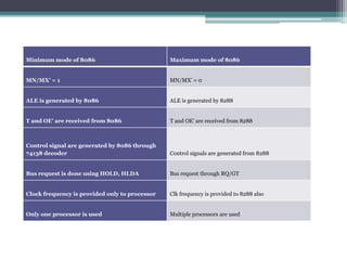
The document discusses the maximum mode of the 8086 microprocessor. In maximum mode, the 8086 is interfaced with other processors like the 8087 to boost performance through multiprocessing. The 8086 acts as the bus master and passes control to other processors via request pins. It uses an 8288 bus controller to generate control signals and latch addresses and data from the bus. Interfacing additional processors allows for floating point coprocessing and increased efficiency. The maximum mode has a more complex circuit than the minimum mode but enables multiprocessing capabilities.
The Most Attractive Pune Call Girls Budhwar Peth 8250192130 Will You Miss Thi...
MAXIMUM MODE OF 8086 MICROPROCESSOR-1.pptx
1. MAXIMUM MODE OF 8086
MICROPROCESSOR
BY LINCOLN OKODE AND
STEPHANY ORARO
2. Maximum mode:
This is the situation when 8086 is not the only processor in a
system rather it is interfaced with other processors such as
8087/8089.
The main aim for interfacing is to boost performance as
multiple processors are working together.
8086 max mode is basically for implementation of allocation
of global resources and passing bus control to other
coprocessor(i.e. second processor in the system), because two
processors can not access system bus at same instant.
3. The resources which are common to all processors are
known as global resources for example database.
The resources which are allocated to a particular
processor are known as local or private resources for
example printers.
All the processors cannot be BUS MASTERS, by default
the 8086 is the bus master.
All processors execute their own program.
4. If some other processor wants to become bus master then it send a request.
Once the other processor is done with the job it sends release signal by
which 8086 becomes bus master again
So there are two such pins so that two other processors can be
interfaced with 8086. If both the pins send simultaneously requests for
bus control access, priority would be considered. GT0’ is more prior
than GT1’.
5.
6. Circuit explantation:
When MN/ MX’ = 0 , 8086 works in max mode that is the max
mode is active low.
Clock is provided by 8284 clock generator.
8288 bus controller- Address form the address bus is
latched into 8282 8-bit latch. Three such latches are required
because address bus is 20 bit. The ALE(Address latch
enable) is connected to STB(Strobe) of the latch. The ALE for
latch is given by 8288 bus controller.
The data bus is operated through 8286 8-bit transceiver. Two
such transceivers are required, because data bus is 16-bit.
7. The transceivers are enabled the DEN signal.
The direction of data is controlled by the DT/R signal.
DEN is connected to OE’ and DT/ R’ is connected to T. Both
DEN and DT/ R’ are given by 8288 bus controller.
8. Control signals for all operations are generated by decoding
S’2, S’1 and S’0 using 8288 bus controller.
9. Bus request is done using RQ’ / GT’ lines interfaced with 8086.
RQ0/GT0 has more priority than RQ1/GT1.
The lock is an active low pin and indicates that the other system bus
masters have not been allowed to gain control of the system bus.
INTA’ is given by 8288, in response to an interrupt on INTR line of
8086.
In max mode, the advanced write signals get enabled one T-state in
advance as compared to normal write signals. This gives slower
devices more time to get ready to accept the data, therefore it
reduces the number of cycles.
10. MRDC (Memory Read Command) : It instructs the memory
to put the contents of the addressed location on the data bus.
MWTC (Memory Write Command) : It instructs the memory
to accept the data on the data bus and load the data into the
addressed memory location.
IORC (I/O Read Command) : It instructs an I/O device to put
the data contained in the addressed port on the data bus.
IOWC (I/0 Write Command) : It instructs an I/O device to
accept the data on the data bus and load the data into the
addressed port.
MCE/PDEN (Master Cascade Enable/Peripheral Data
Enable) : It controls the mode of operation of 8259. It selects
cascade operation for 8259 (interrupt controller) if IOB signal is
grounded and enables the I/O bus transceivers if IOB is tied high.
11. AEN, IOB and CEN : These pins are used in multiprocessor
system. With a single processor in the system, AEN and IOB
are grounded and CEN is tied high. AEN causes the 8288 to
enable the memory control signals. IOB (I/O bus mode) signal
selects either the I/O bus mode or system bus mode operation.
CEN (control enable) input enables the command output pins
on the 8288.
AIOWC/AMWC (Advance I/O Write
Command/Advance Memory Write Command) : These
signals are similar to IOWC and MWTC except that they are
activated one clock pulse earlier. This gives slow interfaces an
extra clock cycle to prepare to input the data.
12. Advantages of max mode of 8086
1. It helps to interface more devices like 8087.This interface is also
called a closely coupled co-Processor configuration. In this 8086
is called as the host and 8087 as Co-processor.
2. It supports multiprocessing, Therefore it helps to increase the
efficiency’
3. The 8087 was the first floating-point coprocessor for the 8086
series of microprocessors. The purpose of the 8087 was to increase
calculations for floating point operations, such as add, sub, multiply,
divide, and square root.
Disadvantages of max mode over min mode :
• It has more complex circuit than min mode
13. Pin differences between minimum mode and maximum mode
Characteristics of these 8 changed pins in maximum mode are
14. Minimum mode of 8086 Maximum mode of 8086
MN/MX’ = 1 MN/MX’ = 0
ALE is generated by 8086 ALE is generated by 8288
T and OE’ are received from 8086 T and OE’ are received from 8288
Control signal are generated by 8086 through
74138 decoder Control signals are generated from 8288
Bus request is done using HOLD, HLDA Bus request through RQ/GT
Clock frequency is provided only to processor Clk frequency is provided to 8288 also
Only one processor is used Multiple processors are used
17. These are explained in steps.
S0,S1,S2 are set at the beginning of bus cycle.
On detecting the change on passive state S0 = S1 = S2 =
1, the 8288 bus controller will output a pulse on its ALE
and apply a required signal to its DT/R pin during T1.
In T2, 8288 will set DEN = 1 thus enabling transceiver.
For an input, 8288 it will activate MRDC or IORC. These
signals are activated until T4. For an output, the AMWC
or AIOWC is activated from T2 to T4 and MWTC or IOWC
is activated from T3 to T4.
The status bits S0 to S2 remain active until T3, and
become passive during T3 and T4.
If ready input is not activated before T3, wait state will be
inserted between T3 and T4.
18. NOTE;
8086 AND 8088 are binary compatible and not pin compatible
and can therefore not be interfaced with each other. Binary
compatibility means that either processor could execute the
same programs.