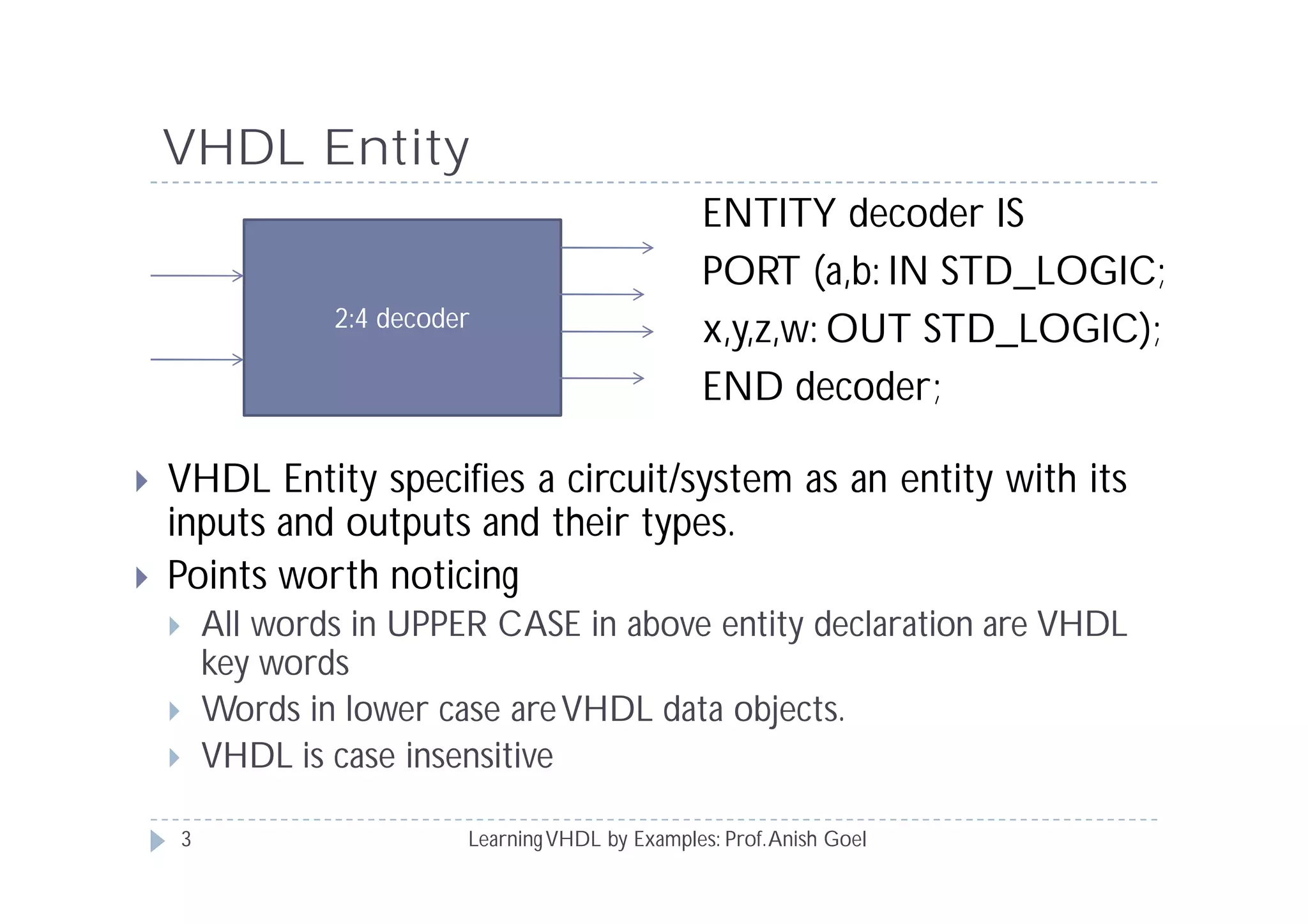
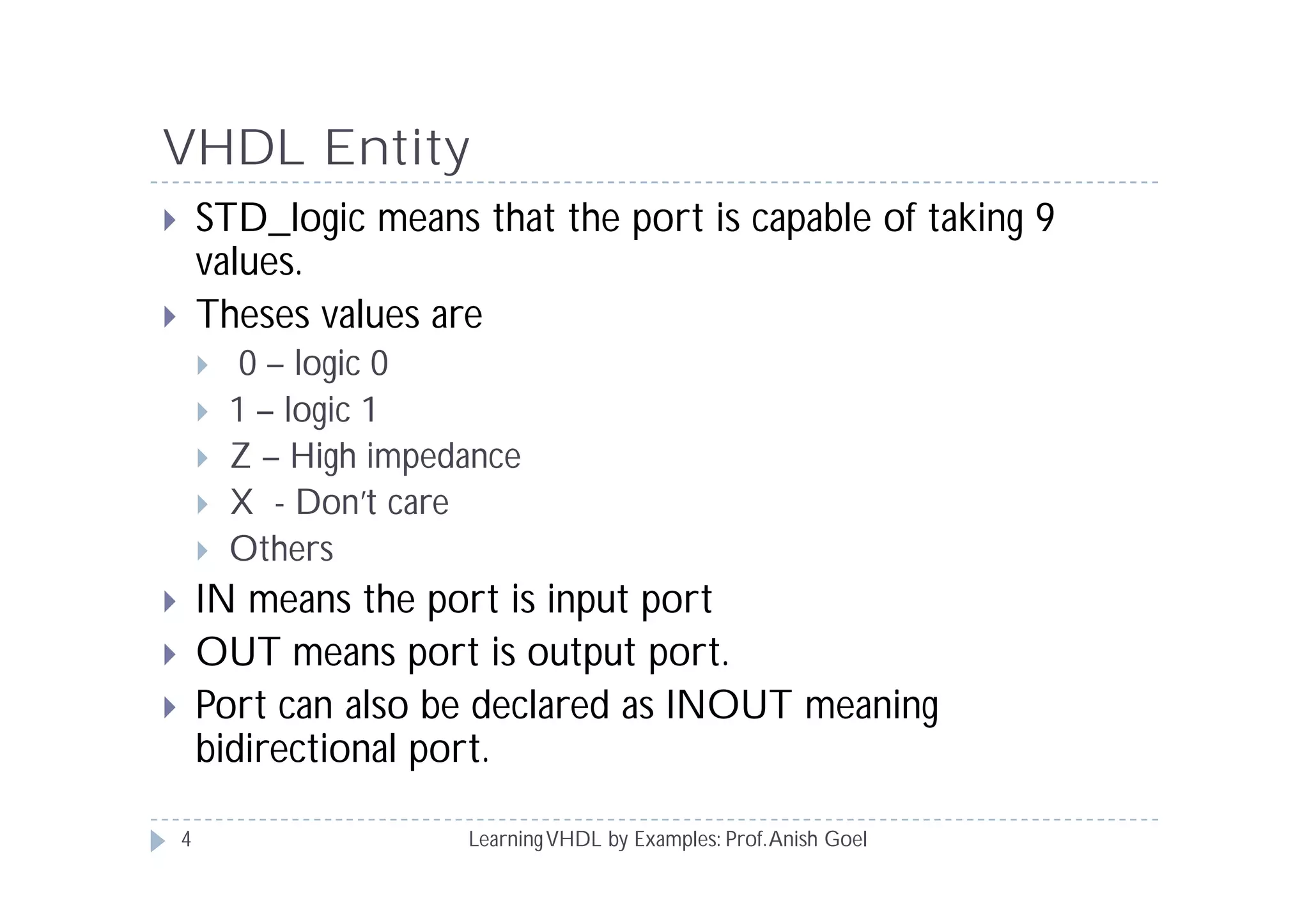
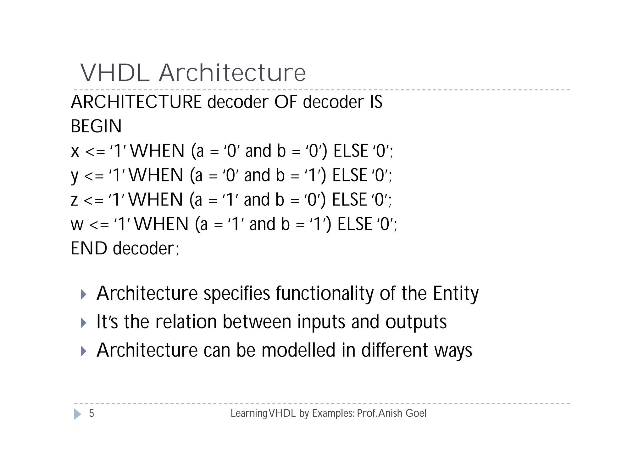
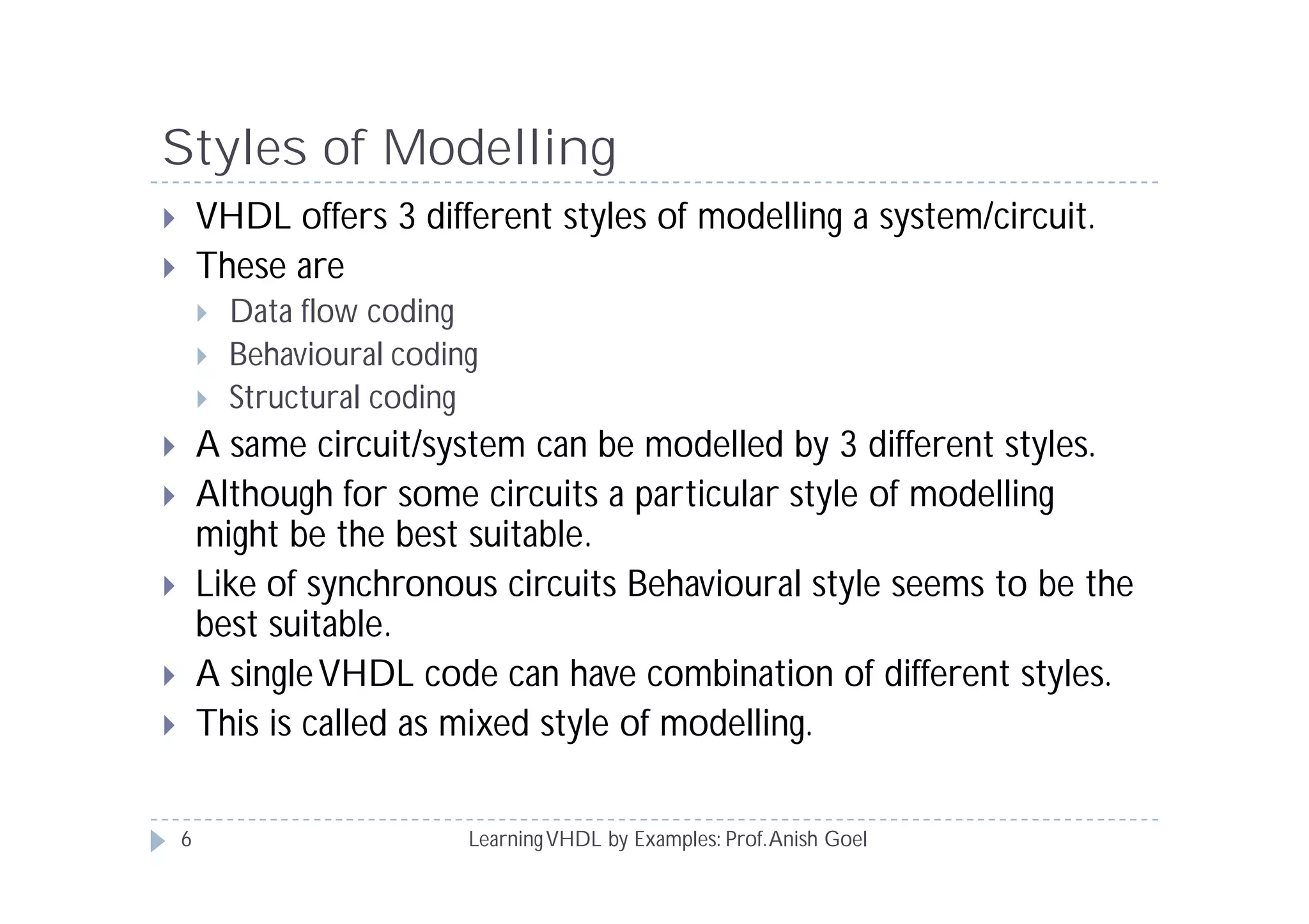
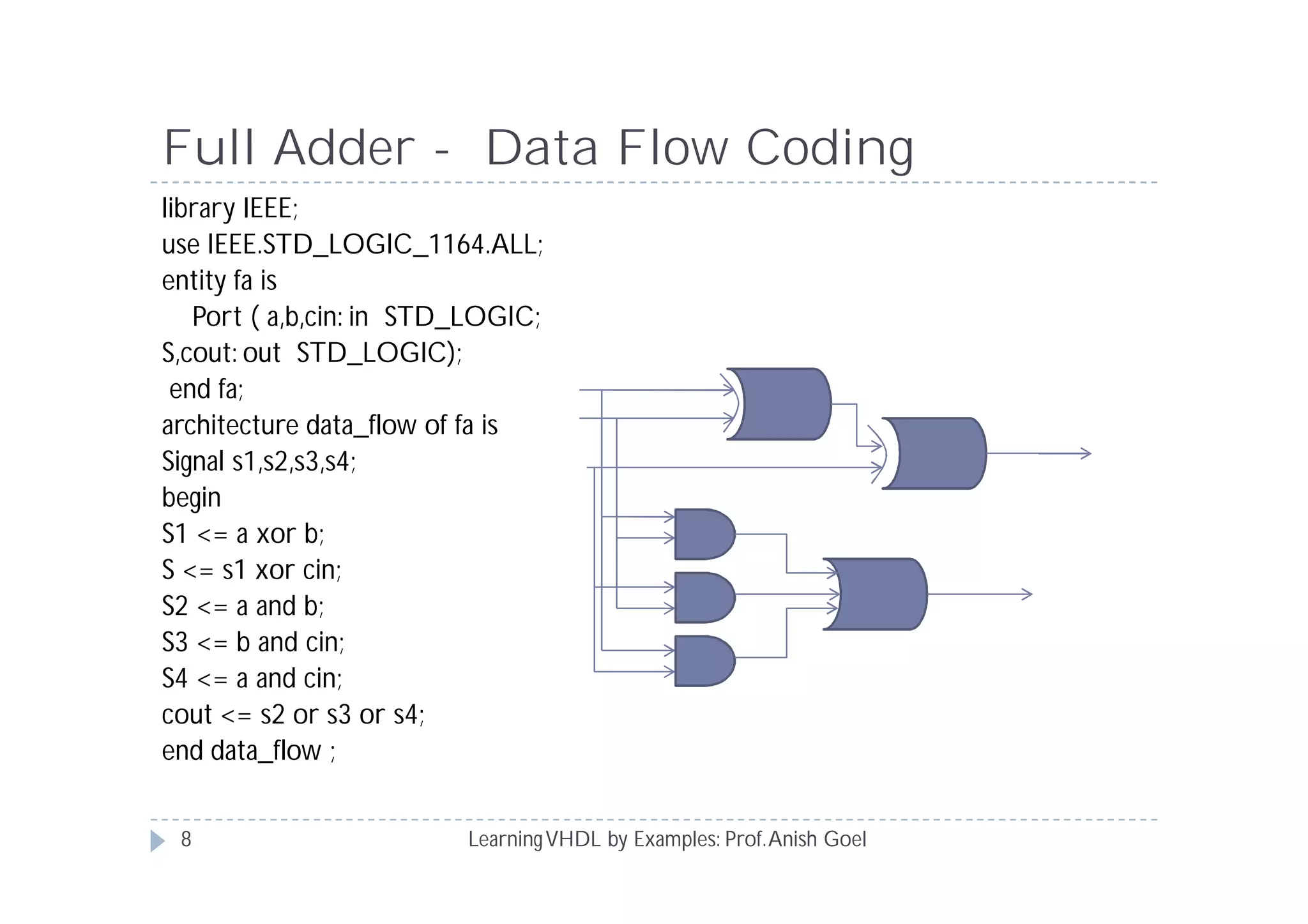
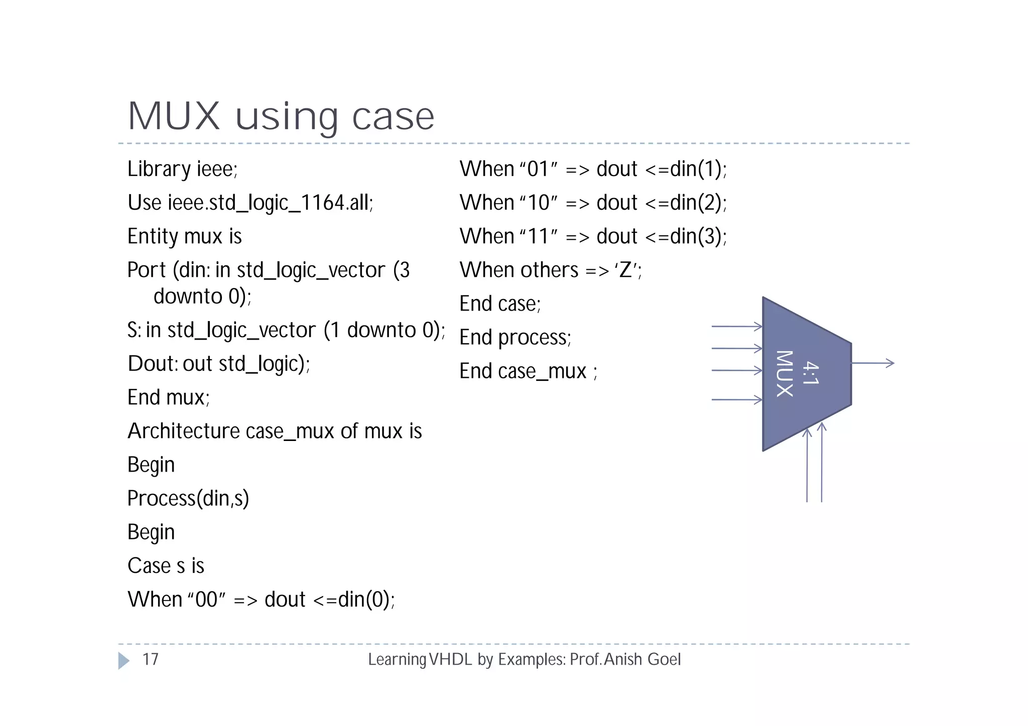
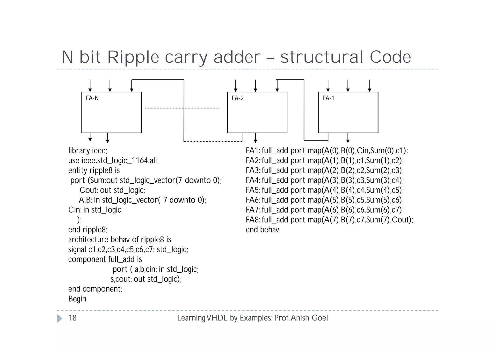
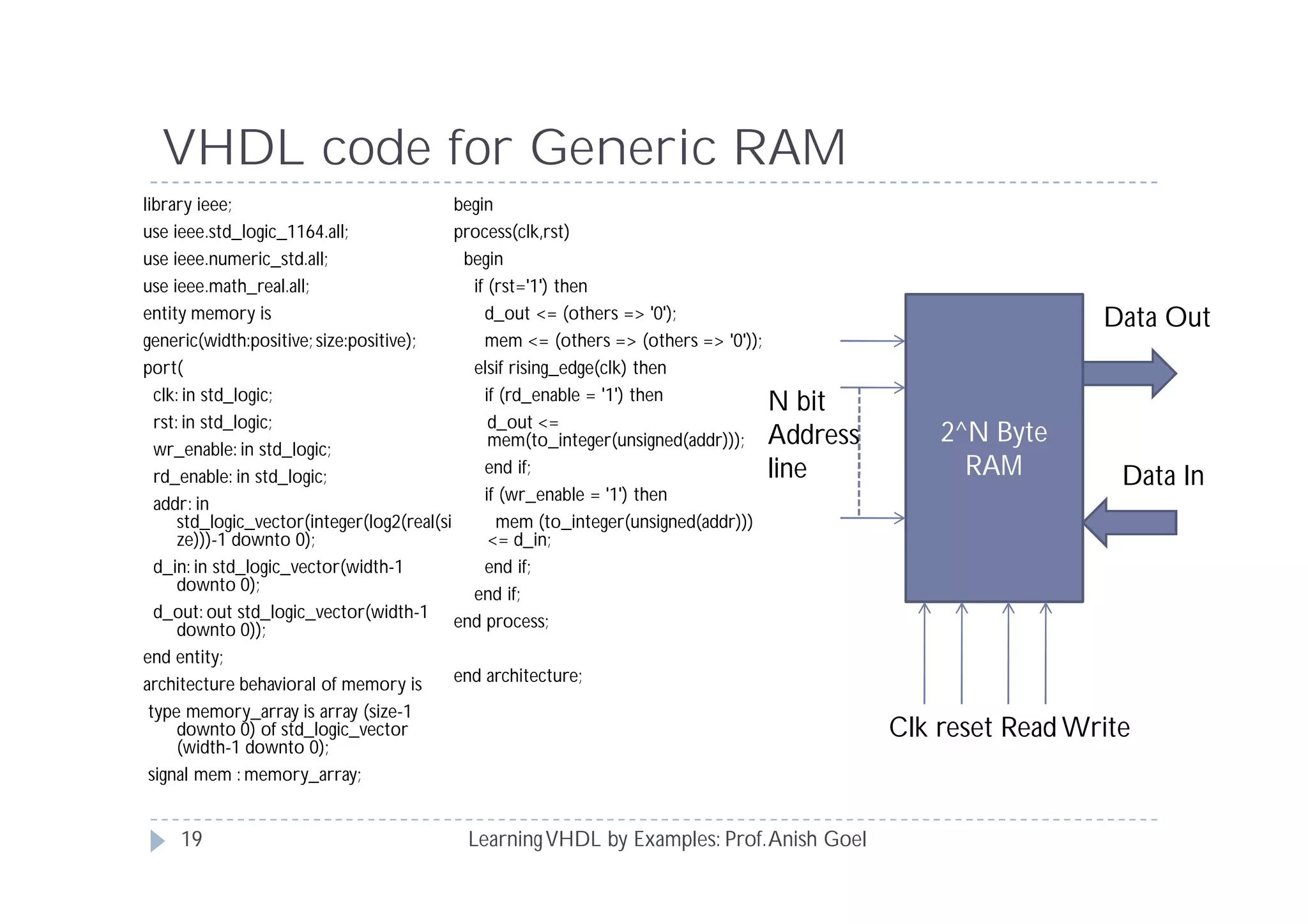
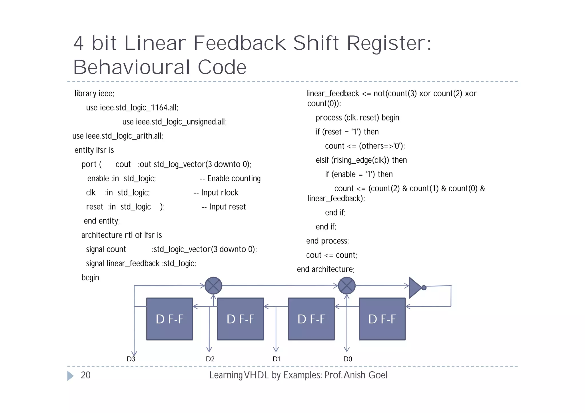
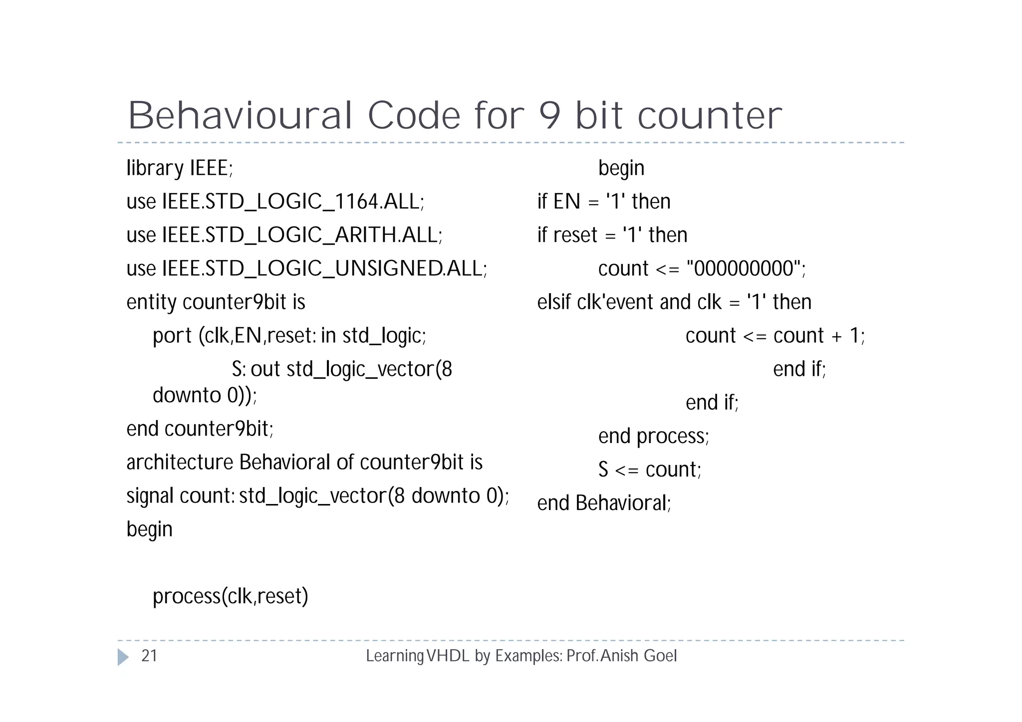
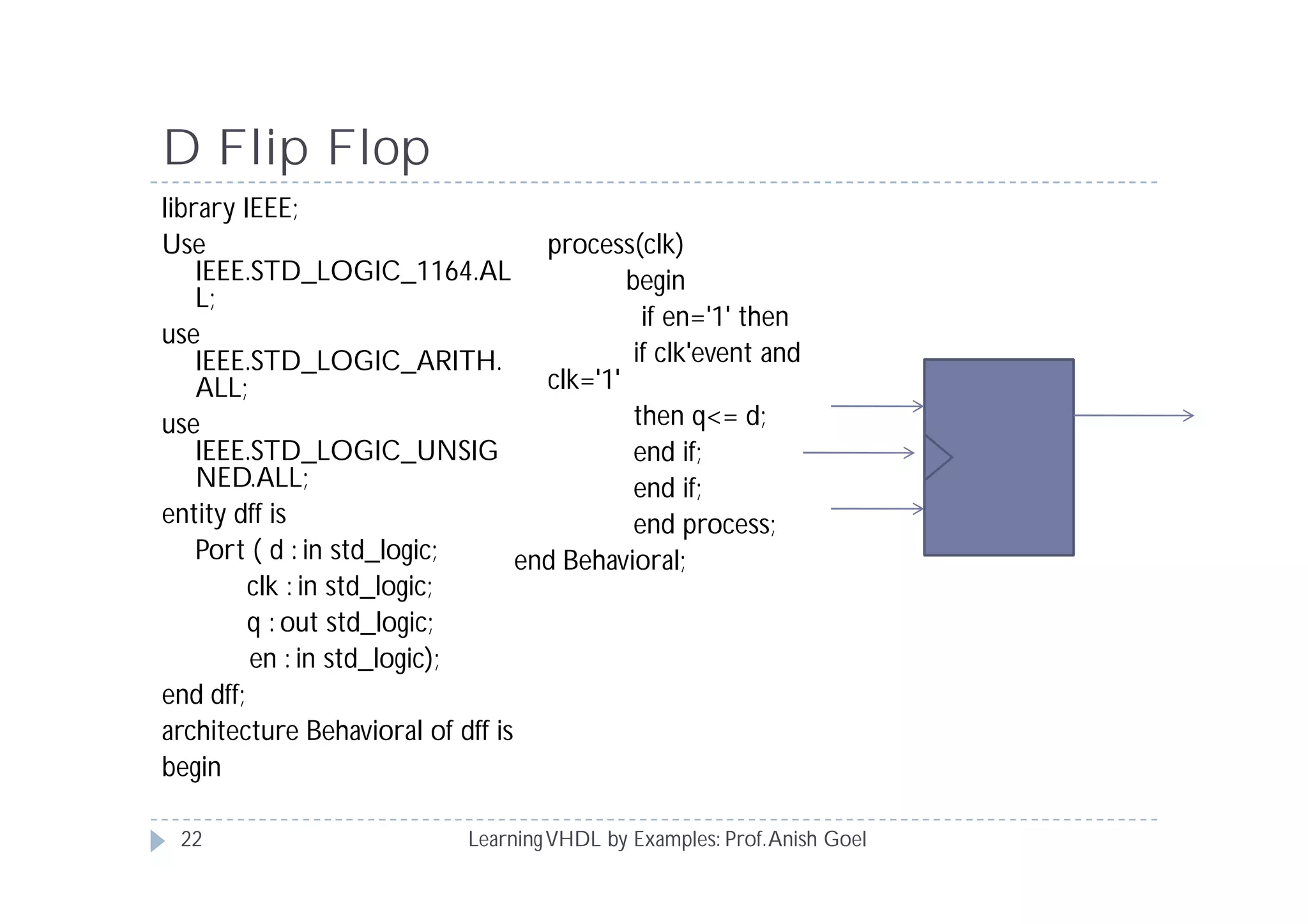
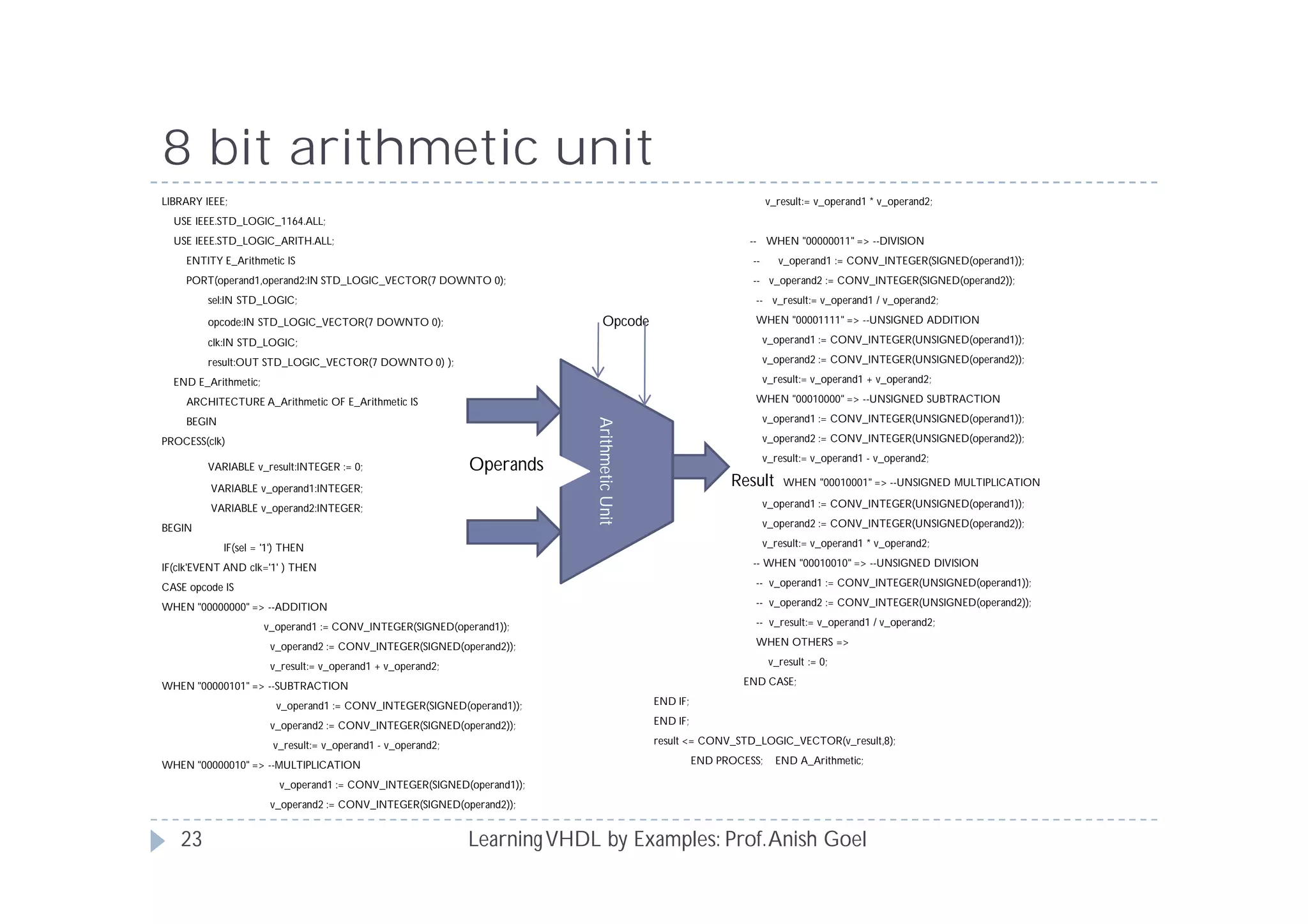
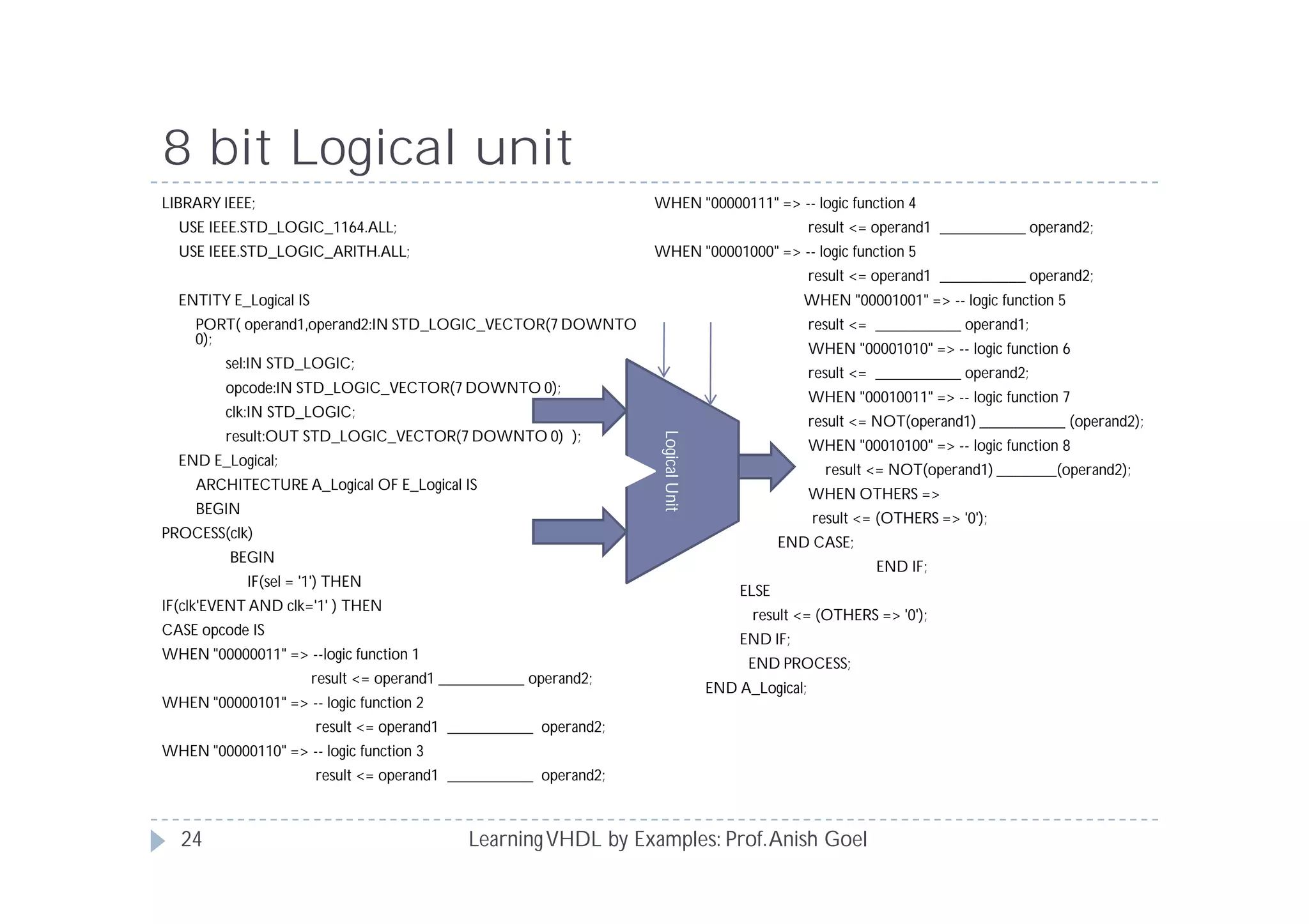
This document provides an overview of VHDL concepts including entity, architecture, data types, modeling styles, assignment statements, and examples. It discusses how to define an entity with inputs and outputs, use architectures to specify functionality, and model systems using data flow, behavioral, and structural styles. It also gives examples of using conditional and concurrent statements like if/case and when/else. Application examples include decoders, multiplexers, counters, arithmetic units, and shift registers.
Yaser Khalifa introduces you to VHDL (VHSIC Hardware Description Language), a hardware description language used in electronic design automation to describe digital and mixed-signal systems such as field-programmable gate arrays and integrated circuits.
Verilog HDL is a hardware description language used to design and document electronic systems. Verilog HDL allows designers to design at various levels of abstraction. It is the most widely used HDL with a user community of more than 50,000 active designers.
A brief history
Verilog HDL originated at Automated Integrated Design Systems (later renamed as Gateway Design Automation) in 1985. The company was privately held at that time by Dr. Prabhu Goel, the inventor of the PODEM test generation algorithm. Verilog HDL was designed by Phil Moorby, who was later to become the Chief Designer for Verilog-XL and the first Corporate Fellow at Cadence Design Systems. Gateway Design Automation grew rapidly with the success of Verilog-XL and was finally acquired by Cadence Design Systems, San Jose, CA in 1989.
Verilog was invented as simulation language. Use of Verilog for synthesis was a complete afterthought. Rumors abound that there were merger discussions between Gateway and Synopsys in the early days, where neither gave the other much chance of success..
In the late 1980's it seemed evident that designers were going to be moving away from proprietary languages like n dot, HiLo and Verilog towards the US Depatment of Defense standard H.D.L., known as the VHSIC Hardware Description Language. VHSIC it self stands for "Very High Speen Intergrated Circuit" BTW).
Perhaps due to such market pressure, Cadence Design Systems decided to open the Verilog language to the public in 1990, and thus OVI (Open Verilog International) was born. Until that time, Verilog HDL was a proprietary language, being the property of Cadence Design Systems. When OVI was formed in 1991, a number of small companies began working on Verilog simulators, including Chronologic Simulation, Frontline Design Automation, and others. The first of these came to market in 1992, and now there are mature Verilog simulators available from many sources.
As a result, the Verilog market has grown substantially. The market for Verilog related tools in 1994 was well over $75,000,000, making it the most commercially significant hardware description language on the market.
An IEEE working group was established in 1993 under the Design Automation Sub-Committee to produce the IEEE Verilog standard 1364. Verilog became IEEE Standard 1364 in 1995.
As an international standard, the Verilog market continued to grow. In 1998 the market for Verilog simulators alone was well over $150,000,000; continuing its dominance.
The IEEE working group released a revised standard in March of 2002, known as IEEE 1364-2001. Significant publication errors marred this release, and a revised version was released in 2003, known as IEEE 1364-2001 Revision C.
Verilog HDL (Hardware Description Language) Training Course for self-taught instructional. User should be familiar with basic digital and logic design. Helpful to have a Verilog simulator while going through examples.
Verilog Tutorial - Verilog HDL Tutorial with ExamplesE2MATRIX
E2MATRIX Research Lab
Opp Phagwara Bus Stand, Backside Axis Bank,
Parmar Complex, Phagwara Punjab (India).
Contact : +91 9041262727
web: www.e2matrix.com -- email: support@e2matrix.com
Simulation tools typically accept full set of Verilog language constructs
Some language constructs and their use in a Verilog description make simulation efficient and are ignored by synthesis tools
Synthesis tools typically accept only a subset of the full Verilog language constructs
In this presentation, Verilog language constructs not supported in Synopsys FPGA Express are in red italics
There are other restrictions not detailed here, see [2].
The Module Concept
Basic design unit
Modules are:
Declared
Instantiated
Modules declarations cannot be nested
This Presentation covers most of VHDL designing basic from scratch.
click the below link for contents
http://eutectics.blogspot.com/2014/01/how-to-design-programs-using-vhdl-all.html
Synthesis Process, synthesis Model, Why Perform Logic synthesis, Resource Sharing,Example of Resource sharing,Pipe-lining,Power Analysis of FPGA Based System
Those slides describe digital design using Verilog HDL,
starting with Design methodologies for any digital circuit then difference between s/w (C/C++) and H/w (Verilog) and the most important constructs that let us start hardware design using Verilog HDL.
HDLs are standard text-based expressions of the structure of electronic systems and their behaviour over time. Like concurrent programming languages, HDL syntax and semantics include explicit notations for expressing concurrency. However, in contrast to most software programming languages, HDLs also include an explicit notion of time, which is a primary attribute of hardware.
Understanding Inductive Bias in Machine LearningSUTEJAS
This presentation explores the concept of inductive bias in machine learning. It explains how algorithms come with built-in assumptions and preferences that guide the learning process. You'll learn about the different types of inductive bias and how they can impact the performance and generalizability of machine learning models.
The presentation also covers the positive and negative aspects of inductive bias, along with strategies for mitigating potential drawbacks. We'll explore examples of how bias manifests in algorithms like neural networks and decision trees.
By understanding inductive bias, you can gain valuable insights into how machine learning models work and make informed decisions when building and deploying them.
We have compiled the most important slides from each speaker's presentation. This year’s compilation, available for free, captures the key insights and contributions shared during the DfMAy 2024 conference.
Industrial Training at Shahjalal Fertilizer Company Limited (SFCL)MdTanvirMahtab2
This presentation is about the working procedure of Shahjalal Fertilizer Company Limited (SFCL). A Govt. owned Company of Bangladesh Chemical Industries Corporation under Ministry of Industries.
Welcome to WIPAC Monthly the magazine brought to you by the LinkedIn Group Water Industry Process Automation & Control.
In this month's edition, along with this month's industry news to celebrate the 13 years since the group was created we have articles including
A case study of the used of Advanced Process Control at the Wastewater Treatment works at Lleida in Spain
A look back on an article on smart wastewater networks in order to see how the industry has measured up in the interim around the adoption of Digital Transformation in the Water Industry.
HEAP SORT ILLUSTRATED WITH HEAPIFY, BUILD HEAP FOR DYNAMIC ARRAYS.
Heap sort is a comparison-based sorting technique based on Binary Heap data structure. It is similar to the selection sort where we first find the minimum element and place the minimum element at the beginning. Repeat the same process for the remaining elements.
The Internet of Things (IoT) is a revolutionary concept that connects everyday objects and devices to the internet, enabling them to communicate, collect, and exchange data. Imagine a world where your refrigerator notifies you when you’re running low on groceries, or streetlights adjust their brightness based on traffic patterns – that’s the power of IoT. In essence, IoT transforms ordinary objects into smart, interconnected devices, creating a network of endless possibilities.
Here is a blog on the role of electrical and electronics engineers in IOT. Let's dig in!!!!
For more such content visit: https://nttftrg.com/
Saudi Arabia stands as a titan in the global energy landscape, renowned for its abundant oil and gas resources. It's the largest exporter of petroleum and holds some of the world's most significant reserves. Let's delve into the top 10 oil and gas projects shaping Saudi Arabia's energy future in 2024.
Cosmetic shop management system project report.pdfKamal Acharya
Buying new cosmetic products is difficult. It can even be scary for those who have sensitive skin and are prone to skin trouble. The information needed to alleviate this problem is on the back of each product, but it's thought to interpret those ingredient lists unless you have a background in chemistry.
Instead of buying and hoping for the best, we can use data science to help us predict which products may be good fits for us. It includes various function programs to do the above mentioned tasks.
Data file handling has been effectively used in the program.
The automated cosmetic shop management system should deal with the automation of general workflow and administration process of the shop. The main processes of the system focus on customer's request where the system is able to search the most appropriate products and deliver it to the customers. It should help the employees to quickly identify the list of cosmetic product that have reached the minimum quantity and also keep a track of expired date for each cosmetic product. It should help the employees to find the rack number in which the product is placed.It is also Faster and more efficient way.
Cosmetic shop management system project report.pdf
learning vhdl by examples
1. Short Term Training Program on
“FPGA Based Digital Systems with Application
to SDR in Cognitive Environment”
Learning VHDL by Examples
Prof. Anish Goel
2. Contents
VHDL Entity and Architecture
VHDL styles of Modelling
Conditional and concurrent assignment statements
LearningVHDL by Examples: Prof.Anish Goel2
3. VHDL Entity
LearningVHDL by Examples: Prof.Anish Goel
VHDL Entity specifies a circuit/system as an entity with its
inputs and outputs and their types.
Points worth noticing
All words in UPPER CASE in above entity declaration are VHDL
key words
Words in lower case areVHDL data objects.
VHDL is case insensitive
2:4 decoder
ENTITY decoder IS
PORT (a,b: IN STD_LOGIC;
x,y,z,w: OUT STD_LOGIC);
END decoder;
3
4. VHDL Entity
LearningVHDL by Examples: Prof.Anish Goel
STD_logic means that the port is capable of taking 9
values.
Theses values are
0 – logic 0
1 – logic 1
Z – High impedance
X - Don’t care
Others
IN means the port is input port
OUT means port is output port.
Port can also be declared as INOUT meaning
bidirectional port.
4
5. VHDL Architecture
LearningVHDL by Examples: Prof.Anish Goel
Architecture specifies functionality of the Entity
It’s the relation between inputs and outputs
Architecture can be modelled in different ways
ARCHITECTURE decoder OF decoder IS
BEGIN
x <= ‘1’ WHEN (a = ‘0’ and b = ‘0’) ELSE ‘0’;
y <= ‘1’WHEN (a = ‘0’ and b = ‘1’) ELSE ‘0’;
z <= ‘1’WHEN (a = ‘1’ and b = ‘0’) ELSE ‘0’;
w <= ‘1’ WHEN (a = ‘1’ and b = ‘1’) ELSE ‘0’;
END decoder;
5
6. Styles of Modelling
LearningVHDL by Examples: Prof.Anish Goel
VHDL offers 3 different styles of modelling a system/circuit.
These are
Data flow coding
Behavioural coding
Structural coding
A same circuit/system can be modelled by 3 different styles.
Although for some circuits a particular style of modelling
might be the best suitable.
Like of synchronous circuits Behavioural style seems to be the
best suitable.
A singleVHDL code can have combination of different styles.
This is called as mixed style of modelling.
6
7. Data Flow Modelling
LearningVHDL by Examples: Prof.Anish Goel
This is also called RTL/Concurrent style of coding.
It has a relation to the flow of signals in the design and
hence data flow.
Generally used to model combinational circuit.
7
8. Full Adder - Data Flow Coding
LearningVHDL by Examples: Prof.Anish Goel
library IEEE;
use IEEE.STD_LOGIC_1164.ALL;
entity fa is
Port ( a,b,cin: in STD_LOGIC;
S,cout: out STD_LOGIC);
end fa;
architecture data_flow of fa is
Signal s1,s2,s3,s4;
begin
S1 <= a xor b;
S <= s1 xor cin;
S2 <= a and b;
S3 <= b and cin;
S4 <= a and cin;
cout <= s2 or s3 or s4;
end data_flow ;
8
9. Behavioural Coding
LearningVHDL by Examples: Prof.Anish Goel
This is used to describe the circuit to its lower level of
abstraction.
Generally used to model synchronous/sequential circuits.
A behavioural code contains PROCESS necessarily.
The flow and execution of code inside process in a
behavioural code is sequential.
9
10. Full Adder - Behavioural Coding
LearningVHDL by Examples: Prof.Anish Goel
library IEEE;
use IEEE.STD_LOGIC_1164.ALL;
entity fa is
Port ( a,b,cin: in STD_LOGIC;
S,cout: out STD_LOGIC);
end fa;
architecture behavioural of fa is
Signal s1,s2,s3,s4;
Begin
Process(a,b,cin)
begin
S1 <= a xor b;
S <= s1 xor cin;
S2 <= a and b;
S3 <= b and cin;
S4 <= a and cin;
cout <= s2 or s3 or s4;
End process;
end behavioural ;
10
11. Structural Style of Coding
LearningVHDL by Examples: Prof.Anish Goel
This style of coding is most suitable for
Creating large circuits/systems that are created from smaller
systems.
Create circuits that have multiple instantiations of a single small
circuit.
It uses previousVHDL codes to model the currentVHDL
codes.
The previous codes must be compiled and present in the
same project as this of code.
The blocks/circuits/systems used to model structural
style of code can be in any style of modelling.
11
12. Full Adder - Structural Coding
LearningVHDL by Examples: Prof.Anish Goel
library IEEE;
use
IEEE.STD_LOGIC_1164
.ALL;
entity fa is
Port ( a,b,cin: in
STD_LOGIC;
S,cout: out STD_LOGIC);
end fa;
architecture behavioural of
fa is
Component gate_xor is
Port (a,b: in std_logic;
C: out std_logic);
End component;
Component gate_and is
Port (a,b: in std_logic;
C: out std_logic);
End component;
Component gate_or is
Port (a,b,c: in std_logic;
D: out std_logic);
End component;
Signal s1,s2,s3,s4;
Begin
G1: gate_xor (a,b,s1);
G2: gate_xor (s1,cin,s);
G3: gate_and (a,b,s2);
G4 gate_and (cin,b,s3);
G5: gate_and (a,cin,s4);
G6: gate_or (s2,s3,s4,cout);
end behavioural ;
12
13. VHDL Statements
LearningVHDL by Examples: Prof.Anish Goel
Two of theVHDL assignment statements are concurrent:
With-Select
When-Else
Other two are sequential
If-then-else
Case
Both are generally used to model conditional circuits.
First 2 cannot be used inside the process and other 2
cannot be used outside the process.
13
14. MUX using when else
LearningVHDL by Examples: Prof.Anish Goel
Library ieee;
Use ieee.std_logic_1164.all;
Entity mux is
Port (din: in std_logic_vector (3 downto 0);
S: in std_logic_vector (1 downto 0);
Dout: out std_logic);
End mux;
Architecture when_else of mux is
Begin
Dout <= din(0) when s = “00” else
din(1) when s = “01” else
din(2) when s = “10” else
din(3) when s = “11” else
‘Z’ when others;
End when_else;
4:1
MUX
14
15. MUX using with-select
LearningVHDL by Examples: Prof.Anish Goel
Library ieee;
Use ieee.std_logic_1164.all;
Entity mux is
Port (din: in std_logic_vector (3 downto 0);
S: in std_logic_vector (1 downto 0);
Dout: out std_logic);
End mux;
Architecture with_select of mux is
Begin
With s select
Dout <= din(0) when “00”,
din(1) when “01”,
din(2) when “10”,
din(3) when “11”,
‘Z’ when others;
End with_select ;
4:1
MUX
15
16. MUX using if-then-else
LearningVHDL by Examples: Prof.Anish Goel
Library ieee;
Use ieee.std_logic_1164.all;
Entity mux is
Port (din: in std_logic_vector (3
downto 0);
S: in std_logic_vector (1 downto 0);
Dout: out std_logic);
End mux;
Architecture if_else of mux is
Begin
Process(din,s)
Begin
If s = “00” then
Dout <= din(0);
Elsif s = “01” then
Dout <= din(1);
Elsif s = “10” then
Dout <= din(2);
Elsif s = “11” then
Dout <= din(3);
Else
Dout <= ‘Z’;
End if;
End process;
End if_else ;
4:1
MUX
16
17. MUX using case
LearningVHDL by Examples: Prof.Anish Goel
Library ieee;
Use ieee.std_logic_1164.all;
Entity mux is
Port (din: in std_logic_vector (3
downto 0);
S: in std_logic_vector (1 downto 0);
Dout: out std_logic);
End mux;
Architecture case_mux of mux is
Begin
Process(din,s)
Begin
Case s is
When “00” => dout <=din(0);
When “01” => dout <=din(1);
When “10” => dout <=din(2);
When “11” => dout <=din(3);
When others => ‘Z’;
End case;
End process;
End case_mux ;
4:1
MUX
17
18. N bit Ripple carry adder – structural Code
LearningVHDL by Examples: Prof.Anish Goel
FA-N FA-2 FA-1
library ieee;
use ieee.std_logic_1164.all;
entity ripple8 is
port (Sum:out std_logic_vector(7 downto 0);
Cout: out std_logic;
A,B: in std_logic_vector( 7 downto 0);
Cin: in std_logic
);
end ripple8;
architecture behav of ripple8 is
signal c1,c2,c3,c4,c5,c6,c7: std_logic;
component full_add is
port ( a,b,cin: in std_logic;
s,cout: out std_logic);
end component;
Begin
FA1: full_add port map(A(0),B(0),Cin,Sum(0),c1);
FA2: full_add port map(A(1),B(1),c1,Sum(1),c2);
FA3: full_add port map(A(2),B(2),c2,Sum(2),c3);
FA4: full_add port map(A(3),B(3),c3,Sum(3),c4);
FA5: full_add port map(A(4),B(4),c4,Sum(4),c5);
FA6: full_add port map(A(5),B(5),c5,Sum(5),c6);
FA7: full_add port map(A(6),B(6),c6,Sum(6),c7);
FA8: full_add port map(A(7),B(7),c7,Sum(7),Cout);
end behav;
18
19. VHDL code for Generic RAM
LearningVHDL by Examples: Prof.Anish Goel
library ieee;
use ieee.std_logic_1164.all;
use ieee.numeric_std.all;
use ieee.math_real.all;
entity memory is
generic(width:positive; size:positive);
port(
clk: in std_logic;
rst: in std_logic;
wr_enable: in std_logic;
rd_enable: in std_logic;
addr: in
std_logic_vector(integer(log2(real(si
ze)))-1 downto 0);
d_in: in std_logic_vector(width-1
downto 0);
d_out: out std_logic_vector(width-1
downto 0));
end entity;
architecture behavioral of memory is
type memory_array is array (size-1
downto 0) of std_logic_vector
(width-1 downto 0);
signal mem : memory_array;
begin
process(clk,rst)
begin
if (rst='1') then
d_out <= (others => '0');
mem <= (others => (others => '0'));
elsif rising_edge(clk) then
if (rd_enable = '1') then
d_out <=
mem(to_integer(unsigned(addr)));
end if;
if (wr_enable = '1') then
mem (to_integer(unsigned(addr)))
<= d_in;
end if;
end if;
end process;
end architecture;
2^N Byte
RAM
N bit
Address
line
Clk reset Read Write
Data Out
Data In
19
20. 4 bit Linear Feedback Shift Register:
Behavioural Code
LearningVHDL by Examples: Prof.Anish Goel
library ieee;
use ieee.std_logic_1164.all;
use ieee.std_logic_unsigned.all;
use ieee.std_logic_arith.all;
entity lfsr is
port ( cout :out std_log_vector(3 downto 0);
enable :in std_logic; -- Enable counting
clk :in std_logic; -- Input rlock
reset :in std_logic ); -- Input reset
end entity;
architecture rtl of lfsr is
signal count :std_logic_vector(3 downto 0);
signal linear_feedback :std_logic;
begin
linear_feedback <= not(count(3) xor count(2) xor
count(0));
process (clk, reset) begin
if (reset = '1') then
count <= (others=>'0');
elsif (rising_edge(clk)) then
if (enable = '1') then
count <= (count(2) & count(1) & count(0) &
linear_feedback);
end if;
end if;
end process;
cout <= count;
end architecture;
D F-F D F-F D F-F D F-F
D0D1D2D3
20
21. Behavioural Code for 9 bit counter
LearningVHDL by Examples: Prof.Anish Goel
library IEEE;
use IEEE.STD_LOGIC_1164.ALL;
use IEEE.STD_LOGIC_ARITH.ALL;
use IEEE.STD_LOGIC_UNSIGNED.ALL;
entity counter9bit is
port (clk,EN,reset: in std_logic;
S: out std_logic_vector(8
downto 0));
end counter9bit;
architecture Behavioral of counter9bit is
signal count: std_logic_vector(8 downto 0);
begin
process(clk,reset)
begin
if EN = '1' then
if reset = '1' then
count <= "000000000";
elsif clk'event and clk = '1' then
count <= count + 1;
end if;
end if;
end process;
S <= count;
end Behavioral;
21
22. D Flip Flop
LearningVHDL by Examples: Prof.Anish Goel
library IEEE;
Use
IEEE.STD_LOGIC_1164.AL
L;
use
IEEE.STD_LOGIC_ARITH.
ALL;
use
IEEE.STD_LOGIC_UNSIG
NED.ALL;
entity dff is
Port ( d : in std_logic;
clk : in std_logic;
q : out std_logic;
en : in std_logic);
end dff;
architecture Behavioral of dff is
begin
process(clk)
begin
if en='1' then
if clk'event and
clk='1'
then q<= d;
end if;
end if;
end process;
end Behavioral;
22
23. 8 bit arithmetic unit
LearningVHDL by Examples: Prof.Anish Goel
LIBRARY IEEE;
USE IEEE.STD_LOGIC_1164.ALL;
USE IEEE.STD_LOGIC_ARITH.ALL;
ENTITY E_Arithmetic IS
PORT(operand1,operand2:IN STD_LOGIC_VECTOR(7 DOWNTO 0);
sel:IN STD_LOGIC;
opcode:IN STD_LOGIC_VECTOR(7 DOWNTO 0); Opcode
clk:IN STD_LOGIC;
result:OUT STD_LOGIC_VECTOR(7 DOWNTO 0) );
END E_Arithmetic;
ARCHITECTURE A_Arithmetic OF E_Arithmetic IS
BEGIN
PROCESS(clk)
VARIABLE v_result:INTEGER := 0; Operands
VARIABLE v_operand1:INTEGER;
VARIABLE v_operand2:INTEGER;
BEGIN
IF(sel = '1') THEN
IF(clk'EVENT AND clk='1' ) THEN
CASE opcode IS
WHEN "00000000" => --ADDITION
v_operand1 := CONV_INTEGER(SIGNED(operand1));
v_operand2 := CONV_INTEGER(SIGNED(operand2));
v_result:= v_operand1 + v_operand2;
WHEN "00000101" => --SUBTRACTION
v_operand1 := CONV_INTEGER(SIGNED(operand1));
v_operand2 := CONV_INTEGER(SIGNED(operand2));
v_result:= v_operand1 - v_operand2;
WHEN "00000010" => --MULTIPLICATION
v_operand1 := CONV_INTEGER(SIGNED(operand1));
v_operand2 := CONV_INTEGER(SIGNED(operand2));
v_result:= v_operand1 * v_operand2;
-- WHEN "00000011" => --DIVISION
-- v_operand1 := CONV_INTEGER(SIGNED(operand1));
-- v_operand2 := CONV_INTEGER(SIGNED(operand2));
-- v_result:= v_operand1 / v_operand2;
WHEN "00001111" => --UNSIGNED ADDITION
v_operand1 := CONV_INTEGER(UNSIGNED(operand1));
v_operand2 := CONV_INTEGER(UNSIGNED(operand2));
v_result:= v_operand1 + v_operand2;
WHEN "00010000" => --UNSIGNED SUBTRACTION
v_operand1 := CONV_INTEGER(UNSIGNED(operand1));
v_operand2 := CONV_INTEGER(UNSIGNED(operand2));
v_result:= v_operand1 - v_operand2;
Result WHEN "00010001" => --UNSIGNED MULTIPLICATION
v_operand1 := CONV_INTEGER(UNSIGNED(operand1));
v_operand2 := CONV_INTEGER(UNSIGNED(operand2));
v_result:= v_operand1 * v_operand2;
-- WHEN "00010010" => --UNSIGNED DIVISION
-- v_operand1 := CONV_INTEGER(UNSIGNED(operand1));
-- v_operand2 := CONV_INTEGER(UNSIGNED(operand2));
-- v_result:= v_operand1 / v_operand2;
WHEN OTHERS =>
v_result := 0;
END CASE;
END IF;
END IF;
result <= CONV_STD_LOGIC_VECTOR(v_result,8);
END PROCESS; END A_Arithmetic;
ArithmeticUnit
23
24. 8 bit Logical unit
LearningVHDL by Examples: Prof.Anish Goel
LIBRARY IEEE;
USE IEEE.STD_LOGIC_1164.ALL;
USE IEEE.STD_LOGIC_ARITH.ALL;
ENTITY E_Logical IS
PORT( operand1,operand2:IN STD_LOGIC_VECTOR(7 DOWNTO
0);
sel:IN STD_LOGIC;
opcode:IN STD_LOGIC_VECTOR(7 DOWNTO 0);
clk:IN STD_LOGIC;
result:OUT STD_LOGIC_VECTOR(7 DOWNTO 0) );
END E_Logical;
ARCHITECTURE A_Logical OF E_Logical IS
BEGIN
PROCESS(clk)
BEGIN
IF(sel = '1') THEN
IF(clk'EVENT AND clk='1' ) THEN
CASE opcode IS
WHEN "00000011" => --logic function 1
result <= operand1 __________ operand2;
WHEN "00000101" => -- logic function 2
result <= operand1 __________ operand2;
WHEN "00000110" => -- logic function 3
result <= operand1 __________ operand2;
WHEN "00000111" => -- logic function 4
result <= operand1 __________ operand2;
WHEN "00001000" => -- logic function 5
result <= operand1 __________ operand2;
WHEN "00001001" => -- logic function 5
result <= __________ operand1;
WHEN "00001010" => -- logic function 6
result <= __________ operand2;
WHEN "00010011" => -- logic function 7
result <= NOT(operand1) __________ (operand2);
WHEN "00010100" => -- logic function 8
result <= NOT(operand1) _______(operand2);
WHEN OTHERS =>
result <= (OTHERS => '0');
END CASE;
END IF;
ELSE
result <= (OTHERS => '0');
END IF;
END PROCESS;
END A_Logical;
LogicalUnit
24
25. PID Controller
LearningVHDL by Examples: Prof.Anish Goel
library ieee;
use ieee.std_logic_1164.all;
use ieee.std_logic_signed.all;
use IEEE.std_logic_arith.all;
entity PIDModule is
Port ( ADC_DATA : in STD_LOGIC_VECTOR (15 downto 0); --16 bit unsigned PID input
DAC_DATA : out STD_LOGIC_VECTOR (15 downto 0); --16 bit unsigned PID output
CLK1 : in STD_LOGIC;
SetVal: in std_logic_vector(15 downto 0));
end PIDModule;
architecture Behavioral of PIDModule is
type statetypes is (Reset, CalculateNewError, CalculatePID, DivideKg,
Write2DAC, Soverload, ConvDac );
signal state,next_state : statetypes := Reset;
signal Kp : integer := 10;
signal Kd : integer :=20;
signal Ki : integer :=1;
signal Kg : integer := 256;
signal Output : integer := 1;
-- signal SetVal : integer := 16384;
signal sAdc : integer := 0 ;
signal Error: integer := 0;
signal p,i,d : integer := 0;
signal DacDataCarrier : std_logic_vector (15 downto 0);
signal AdcDataCarrier : std_logic_vector (15 downto 0);
begin
PROCESS (clk1)
variable Output_Old : integer := 0;
variable Error_Old : integer := 0;
BEGIN
IF CLK1'EVENT AND CLK1='1' THEN
state <= next_state;
END IF;
case state is
when Reset =>
sAdc <= conv_integer(ADC_DATA); --Get the input for PID
next_state <= CalculateNewError;
Error_Old := Error; --Capture old error
Output_Old := Output; --Capture old PID output
when CalculateNewError => next_state <= CalculatePID;
Error <= (conv_integer(SetVal)-sAdc); --Calculate
when CalculatePID => next_state <= DivideKg;
p <= Kp*(Error); --Calculate PID
i <= Ki*(Error+Error_Old);
d <= Kd *(Error-Error_Old);
when DivideKg => next_state <= SOverload;
Output <= Output_Old+((p+i+d)/16384); --Calculate new output
when SOverload =>
next_state <=ConvDac;
if Output > 65535 then
Output <= 65535 ;
end if;
if Output < 1 then
Output <= 1;
end if;
when ConvDac => --Send the output to port
DacDataCarrier <= conv_std_logic_vector(Output ,16);
next_state <=Write2DAC;
when Write2DAC =>
next_state <= Reset;
DAC_DATA <= DacDataCarrier;
end case;
END PROCESS;
end Behavioral;
25
26. SIPO Shift Register
LearningVHDL by Examples: Prof.Anish Goel
library IEEE;
use IEEE.STD_LOGIC_1164.ALL;
entity sipo is
Port ( sin : in STD_LOGIC;
clk : in STD_LOGIC;
rst : in STD_LOGIC;
pout : out
STD_LOGIC_VECTOR (15
downto 0));
end sipo;
architecture Behavioral of sipo is
signal cnt: std_logic_vector(15
downto 0);
Begin
process(clk,rst)
begin
if rst = '1' then
cnt <= "0000000000000000";
else if clk'event and clk = '1' then
cnt(0) <= cnt(1);
cnt(1) <= cnt(2);
cnt(2) <= cnt(3);
cnt(3) <= cnt(4);
cnt(4) <= cnt(5);
cnt(5) <= cnt(6);
cnt(6) <= cnt(7);
cnt(7) <= cnt(8);
cnt(8) <= cnt(9);
cnt(9) <= cnt(10);
cnt(10) <= cnt(11);
cnt(11) <= cnt(12);
cnt(12) <= cnt(13);
cnt(13) <= cnt(14);
cnt(14) <= cnt(15);
cnt(15) <= sin;
end if;
end if;
end process;
pout <= cnt;
end Behavioral;
FF - 16 FF - 15 FF - 14 FF - 1
Sin
Rst
Clk
D15 D14 D13 D0
26
27. 8 Bit Tri-State Buffer
LearningVHDL by Examples: Prof.Anish Goel
library IEEE;
use IEEE.STD_LOGIC_1164.ALL;
entity buff is
Port ( a : in STD_LOGIC_vector(7 downto 0);
b : out STD_LOGIC_vector(7 downto 0);
en : in STD_LOGIC);
end buff;
architecture Behavioral of buff is
begin
process(a,en)
begin
if en = '1' then
b <= a;
else
b <= "ZZZZZZZZ";
end if;
end process;
end Behavioral;
Buf
en
a b
27