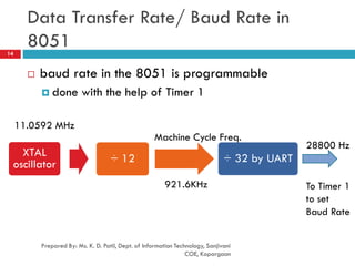
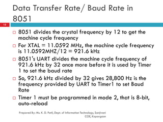
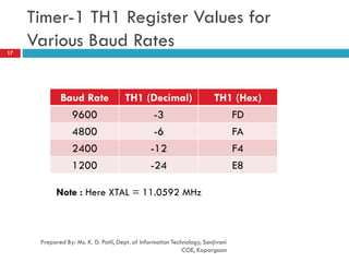
1
Unit 5: 8051 Serial Port Programming
Part 1
Subject: Processor Architecture & Interfacing
(SPPU, Pune 2015 Course of Information Technology)
Class: SEIT Semester: II
Prepared By,
Ms. K. D. Patil, Assistant Professor
Department of Information Technology
(NBA accredited)
Sanjivani College of Engineering, Kopargaon-423603.
Maharashtra, India.
(An Autonomous Institute, Affiliated with SPPU, Pune.)
NAAC ‘A’ Grade Accredited, ISO 9001:2015 certified
Contents
Prepared By: Ms. K. D. Patil, Dept. of Information Technology, Sanjivani
COE, Kopargaon
2
 Part 1
 Basics of Communication
 Serial Vs Parallel communication
 Synchronous Vs Asynchronous communication
 Data Framing in Asynchronous Serial Communication
 Baud Rate
 Part 2
 Special Function Registers
 Operating modes of Serial Communication
 Doubling Baud Rate in 8051
 Part 3
 Importance of TI Flag
 Importance of RI Flag
 Examples
Learning Outcomes
Prepared By: Ms. K. D. Patil, Dept. of Information Technology, Sanjivani COE, Kopargaon
3
 Student will be able to
 Learn basics of 8051 serial communication
 Learn Special Function Registers and their
configurations
 Apply knowledge of 8051 assembly language to
write a code for 8051 serial port
Basics
 When a processor communicates
with outside world, it provides
the data in byte-sized chunks
 Two ways
 Serial
 To transfer to a device located
many meters away, the serial
method is used
 The data is sent one bit at a time
 Eg. Telephone Lines connecting
different cities
 Parallel
 often 8 or more lines (wire
conductors) are used to transfer
data to a device that is only a
few feet away
4
Prepared By: Ms. K. D. Patil, Dept. of Information Technology, Sanjivani
COE, Kopargaon
Basics
Prepared By: Ms. K. D. Patil, Dept. of Information Technology, Sanjivani
COE, Kopargaon
5
 At the transmitting end, the byte of data must be converted
to serial bits using parallel-in-serial-out (PISO) shift register
 At the receiving end, there is a serial-in-parallel-out (SIPO)
shift register to receive the serial data and pack them into
byte
 When the distance is short, the digital signal can be
transferred as it is on a simple wire and requires no
modulation
 If data is to be transferred on the telephone line, it must be
converted from 0s and 1s to audio tones
 This conversion is performed by a device called a modem,
“Modulator/demodulator”
Basics
Prepared By: Ms. K. D. Patil, Dept. of Information Technology, Sanjivani
COE, Kopargaon
6
 Serial data communication uses two methods
 Synchronous method
 transfers a block of data at a time
 Asynchronous method
 transfers a single byte at a time
 It is possible to write software to use either of these
methods, but the programs can be tedious and long
 There are special IC chips made by many
manufacturers for serial communications
 UART (Universal Asynchronous Receiver Transmitter)
 USART (Universal Synchronous-Asynchronous Receiver-
Transmitter)
Summary
Prepared By: Ms. K. D. Patil, Dept. of Information Technology, Sanjivani
COE, Kopargaon
7
Parallel Data Transfer Serial Data Transfer
8 bits of data is transferred at a
time
One bit of data is transferred at
a time
8 lines required to be connected Only 2 lines required to be
connected
Data transfer is faster Data transfer is slow
Synchronous Data Transfer Asynchronous Data Transfer
Transfers BLOCK of character at a
time
Transfers ONE character at a time
No start & stop bit START & STOP bit is present
Simplex, Half and Full Duplex Transfer
Prepared By: Ms. K. D. Patil, Dept. of Information Technology, Sanjivani
COE, Kopargaon
8
Simplex, Half and Full Duplex Transfer
Prepared By: Ms. K. D. Patil, Dept. of Information Technology, Sanjivani
COE, Kopargaon
9
 Simplex
 Eg. Printer
 If data can be transmitted and received, it is a
duplex transmission
 If data transmitted one way a time, it is referred to as
half duplex
 If data can go both ways at a time, it is full duplex
 It requires two wire conductors for the data lines, one for
transmission and one for reception
Asynchronous Serial Communication
and Data Framing
Prepared By: Ms. K. D. Patil, Dept. of Information Technology, Sanjivani
COE, Kopargaon
10
 The data receiving is all 0s and 1s
 To make sense of the data, sender and receiver agree on a set of
rules called as Protocols
 how the data is packed
 how many bits/character
 when the data begins and ends
 Asynchronous serial data communication is widely used for
character-oriented transmissions
 Each character is placed in between start and stop bits, this is
called framing
 Block-oriented data transfers use the synchronous method
 The start bit is always one bit, but the stop bit can be one or two
bits
Asynchronous Serial Communication
and Data Framing11
 The start bit is always a 0 (low) and the stop bit(s) is
1 (high)
Data Transfer Rate
Prepared By: Ms. K. D. Patil, Dept. of Information Technology, Sanjivani
COE, Kopargaon
12
 The rate of data transfer in serial data
communication is stated in bps (bits per second)
 Another widely used terminology for bps is baud
rate
 In Modem Technology, It is defined as the number of
signal changes per second
 Because In modems, there are occasions when a
single change of signal transfers several bits of
data
Data Transfer Rate
Prepared By: Ms. K. D. Patil, Dept. of Information Technology, Sanjivani
COE, Kopargaon
13
 The data transfer rate of given computer system depends on
communication ports incorporated into that system
 IBM PC/XT could transfer data at the rate of 100 to 9600 bps
 Pentium-based PCs transfer data at rates as high as 56K bps
 In asynchronous serial data communication, the baud rate is
limited to 100K bps
 To allow data transfer between the PC and an 8051 system
without any error, we must make sure that the baud rate of
8051 system matches the baud rate of the PC’s COM port
Data Transfer Rate/ Baud Rate in
8051
Prepared By: Ms. K. D. Patil, Dept. of Information Technology, Sanjivani
COE, Kopargaon
14
 baud rate in the 8051 is programmable
 done with the help of Timer 1
XTAL
oscillator ÷ 12 ÷ 32 by UART
11.0592 MHz
Machine Cycle Freq.
921.6KHz
28800 Hz
To Timer 1
to set
Baud Rate
Data Transfer Rate/ Baud Rate in
8051
Prepared By: Ms. K. D. Patil, Dept. of Information Technology, Sanjivani
COE, Kopargaon
15
 8051 divides the crystal frequency by 12 to get the
machine cycle frequency
 For XTAL = 11.0592 MHz, the machine cycle frequency
is 11.0592MHZ/12 = 921.6 kHz
 8051's UART divides the machine cycle frequency of
921.6 kHz by 32 once more before it is used by Timer
1 to set the baud rate
 So, 921.6 kHz divided by 32 gives 28,800 Hz is the
frequency provided by UART to Timer1 to set Baud
Rate
 Timer 1 must be programmed in mode 2, that is 8-bit,
auto-reload
Example
Prepared By: Ms. K. D. Patil, Dept. of Information Technology, Sanjivani
COE, Kopargaon
16
 With XTAL = 11.0592 MHz, find the TH1 value needed to have
the following baud rates. (a) 9600 (b) 2400 (c) 1200
Solution:
The machine cycle frequency of 8051 = 11.0592 / 12 = 921.6 kHz,
and 921.6 kHz / 32 = 28,800 Hz is frequency by UART to timer 1 to
set baud rate.
(a) 28,800 / 3 = 9600 where -3 = FD (hex) is loaded into TH1
(b) 28,800 / 12 = 2400 where -12 = F4 (hex) is loaded into TH1
(c) 28,800 / 24 = 1200 where -24 = E8 (hex) is loaded into TH1
Notice that dividing 1/12 of the crystal frequency by 32 is the
default value upon activation of the 8051 RESET pin.
Timer-1 TH1 Register Values for
Various Baud Rates
Prepared By: Ms. K. D. Patil, Dept. of Information Technology, Sanjivani
COE, Kopargaon
17
Baud Rate TH1 (Decimal) TH1 (Hex)
9600 -3 FD
4800 -6 FA
2400 -12 F4
1200 -24 E8
Note : Here XTAL = 11.0592 MHz
Reference
Prepared By: Ms. K. D. Patil, Dept. of Information Technology, Sanjivani
COE, Kopargaon
18
 “The 8051 Microcontroller and Embedded Systems
using Assembly and C” , Muhammad Ali Mazidi,
Janice Gillispie Mazidi, Rolin D. McKinlay, Second
Edition, Pearson publication
Prepared By: Ms. K. D. Patil, Dept. of Information Technology, Sanjivani
COE, Kopargaon
19

SE PAI Unit 5_Serial Port Programming in 8051 microcontroller_Part 1

  • 1.
    1 Unit 5: 8051Serial Port Programming Part 1 Subject: Processor Architecture & Interfacing (SPPU, Pune 2015 Course of Information Technology) Class: SEIT Semester: II Prepared By, Ms. K. D. Patil, Assistant Professor Department of Information Technology (NBA accredited) Sanjivani College of Engineering, Kopargaon-423603. Maharashtra, India. (An Autonomous Institute, Affiliated with SPPU, Pune.) NAAC ‘A’ Grade Accredited, ISO 9001:2015 certified
  • 2.
    Contents Prepared By: Ms.K. D. Patil, Dept. of Information Technology, Sanjivani COE, Kopargaon 2  Part 1  Basics of Communication  Serial Vs Parallel communication  Synchronous Vs Asynchronous communication  Data Framing in Asynchronous Serial Communication  Baud Rate  Part 2  Special Function Registers  Operating modes of Serial Communication  Doubling Baud Rate in 8051  Part 3  Importance of TI Flag  Importance of RI Flag  Examples
  • 3.
    Learning Outcomes Prepared By:Ms. K. D. Patil, Dept. of Information Technology, Sanjivani COE, Kopargaon 3  Student will be able to  Learn basics of 8051 serial communication  Learn Special Function Registers and their configurations  Apply knowledge of 8051 assembly language to write a code for 8051 serial port
  • 4.
    Basics  When aprocessor communicates with outside world, it provides the data in byte-sized chunks  Two ways  Serial  To transfer to a device located many meters away, the serial method is used  The data is sent one bit at a time  Eg. Telephone Lines connecting different cities  Parallel  often 8 or more lines (wire conductors) are used to transfer data to a device that is only a few feet away 4 Prepared By: Ms. K. D. Patil, Dept. of Information Technology, Sanjivani COE, Kopargaon
  • 5.
    Basics Prepared By: Ms.K. D. Patil, Dept. of Information Technology, Sanjivani COE, Kopargaon 5  At the transmitting end, the byte of data must be converted to serial bits using parallel-in-serial-out (PISO) shift register  At the receiving end, there is a serial-in-parallel-out (SIPO) shift register to receive the serial data and pack them into byte  When the distance is short, the digital signal can be transferred as it is on a simple wire and requires no modulation  If data is to be transferred on the telephone line, it must be converted from 0s and 1s to audio tones  This conversion is performed by a device called a modem, “Modulator/demodulator”
  • 6.
    Basics Prepared By: Ms.K. D. Patil, Dept. of Information Technology, Sanjivani COE, Kopargaon 6  Serial data communication uses two methods  Synchronous method  transfers a block of data at a time  Asynchronous method  transfers a single byte at a time  It is possible to write software to use either of these methods, but the programs can be tedious and long  There are special IC chips made by many manufacturers for serial communications  UART (Universal Asynchronous Receiver Transmitter)  USART (Universal Synchronous-Asynchronous Receiver- Transmitter)
  • 7.
    Summary Prepared By: Ms.K. D. Patil, Dept. of Information Technology, Sanjivani COE, Kopargaon 7 Parallel Data Transfer Serial Data Transfer 8 bits of data is transferred at a time One bit of data is transferred at a time 8 lines required to be connected Only 2 lines required to be connected Data transfer is faster Data transfer is slow Synchronous Data Transfer Asynchronous Data Transfer Transfers BLOCK of character at a time Transfers ONE character at a time No start & stop bit START & STOP bit is present
  • 8.
    Simplex, Half andFull Duplex Transfer Prepared By: Ms. K. D. Patil, Dept. of Information Technology, Sanjivani COE, Kopargaon 8
  • 9.
    Simplex, Half andFull Duplex Transfer Prepared By: Ms. K. D. Patil, Dept. of Information Technology, Sanjivani COE, Kopargaon 9  Simplex  Eg. Printer  If data can be transmitted and received, it is a duplex transmission  If data transmitted one way a time, it is referred to as half duplex  If data can go both ways at a time, it is full duplex  It requires two wire conductors for the data lines, one for transmission and one for reception
  • 10.
    Asynchronous Serial Communication andData Framing Prepared By: Ms. K. D. Patil, Dept. of Information Technology, Sanjivani COE, Kopargaon 10  The data receiving is all 0s and 1s  To make sense of the data, sender and receiver agree on a set of rules called as Protocols  how the data is packed  how many bits/character  when the data begins and ends  Asynchronous serial data communication is widely used for character-oriented transmissions  Each character is placed in between start and stop bits, this is called framing  Block-oriented data transfers use the synchronous method  The start bit is always one bit, but the stop bit can be one or two bits
  • 11.
    Asynchronous Serial Communication andData Framing11  The start bit is always a 0 (low) and the stop bit(s) is 1 (high)
  • 12.
    Data Transfer Rate PreparedBy: Ms. K. D. Patil, Dept. of Information Technology, Sanjivani COE, Kopargaon 12  The rate of data transfer in serial data communication is stated in bps (bits per second)  Another widely used terminology for bps is baud rate  In Modem Technology, It is defined as the number of signal changes per second  Because In modems, there are occasions when a single change of signal transfers several bits of data
  • 13.
    Data Transfer Rate PreparedBy: Ms. K. D. Patil, Dept. of Information Technology, Sanjivani COE, Kopargaon 13  The data transfer rate of given computer system depends on communication ports incorporated into that system  IBM PC/XT could transfer data at the rate of 100 to 9600 bps  Pentium-based PCs transfer data at rates as high as 56K bps  In asynchronous serial data communication, the baud rate is limited to 100K bps  To allow data transfer between the PC and an 8051 system without any error, we must make sure that the baud rate of 8051 system matches the baud rate of the PC’s COM port
  • 14.
    Data Transfer Rate/Baud Rate in 8051 Prepared By: Ms. K. D. Patil, Dept. of Information Technology, Sanjivani COE, Kopargaon 14  baud rate in the 8051 is programmable  done with the help of Timer 1 XTAL oscillator ÷ 12 ÷ 32 by UART 11.0592 MHz Machine Cycle Freq. 921.6KHz 28800 Hz To Timer 1 to set Baud Rate
  • 15.
    Data Transfer Rate/Baud Rate in 8051 Prepared By: Ms. K. D. Patil, Dept. of Information Technology, Sanjivani COE, Kopargaon 15  8051 divides the crystal frequency by 12 to get the machine cycle frequency  For XTAL = 11.0592 MHz, the machine cycle frequency is 11.0592MHZ/12 = 921.6 kHz  8051's UART divides the machine cycle frequency of 921.6 kHz by 32 once more before it is used by Timer 1 to set the baud rate  So, 921.6 kHz divided by 32 gives 28,800 Hz is the frequency provided by UART to Timer1 to set Baud Rate  Timer 1 must be programmed in mode 2, that is 8-bit, auto-reload
  • 16.
    Example Prepared By: Ms.K. D. Patil, Dept. of Information Technology, Sanjivani COE, Kopargaon 16  With XTAL = 11.0592 MHz, find the TH1 value needed to have the following baud rates. (a) 9600 (b) 2400 (c) 1200 Solution: The machine cycle frequency of 8051 = 11.0592 / 12 = 921.6 kHz, and 921.6 kHz / 32 = 28,800 Hz is frequency by UART to timer 1 to set baud rate. (a) 28,800 / 3 = 9600 where -3 = FD (hex) is loaded into TH1 (b) 28,800 / 12 = 2400 where -12 = F4 (hex) is loaded into TH1 (c) 28,800 / 24 = 1200 where -24 = E8 (hex) is loaded into TH1 Notice that dividing 1/12 of the crystal frequency by 32 is the default value upon activation of the 8051 RESET pin.
  • 17.
    Timer-1 TH1 RegisterValues for Various Baud Rates Prepared By: Ms. K. D. Patil, Dept. of Information Technology, Sanjivani COE, Kopargaon 17 Baud Rate TH1 (Decimal) TH1 (Hex) 9600 -3 FD 4800 -6 FA 2400 -12 F4 1200 -24 E8 Note : Here XTAL = 11.0592 MHz
  • 18.
    Reference Prepared By: Ms.K. D. Patil, Dept. of Information Technology, Sanjivani COE, Kopargaon 18  “The 8051 Microcontroller and Embedded Systems using Assembly and C” , Muhammad Ali Mazidi, Janice Gillispie Mazidi, Rolin D. McKinlay, Second Edition, Pearson publication
  • 19.
    Prepared By: Ms.K. D. Patil, Dept. of Information Technology, Sanjivani COE, Kopargaon 19