Serial communication uses single data lines, making it cheaper than parallel communication but slower. Serial communication can be synchronous or asynchronous. Asynchronous serial communication in the 8051 uses UART and transmits data in frames that include start bits, data bits, and stop bits to synchronize the transmitter and receiver. The 8051 has registers like SBUF, SCON and flags like TI and RI that help control serial data transmission and reception by indicating when data is ready to be sent or received.
This presentation discusses the Serial Communication features in 8051, the support for UART. It also discusses serial vs parallel communication, simplex, duplex and full-duplex modes, MAX232, RS232 standards
This presentation discusses the Serial Communication features in 8051, the support for UART. It also discusses serial vs parallel communication, simplex, duplex and full-duplex modes, MAX232, RS232 standards
this presentation contains all sort of information regarding USCI(Universal Serial Communication Interface)
UART, SPI, I2C etc.
this will be very helpful to the people those who are planning or starting projects or want to get idea how devices interfaced.
Immunizing Image Classifiers Against Localized Adversary Attacksgerogepatton
This paper addresses the vulnerability of deep learning models, particularly convolutional neural networks
(CNN)s, to adversarial attacks and presents a proactive training technique designed to counter them. We
introduce a novel volumization algorithm, which transforms 2D images into 3D volumetric representations.
When combined with 3D convolution and deep curriculum learning optimization (CLO), itsignificantly improves
the immunity of models against localized universal attacks by up to 40%. We evaluate our proposed approach
using contemporary CNN architectures and the modified Canadian Institute for Advanced Research (CIFAR-10
and CIFAR-100) and ImageNet Large Scale Visual Recognition Challenge (ILSVRC12) datasets, showcasing
accuracy improvements over previous techniques. The results indicate that the combination of the volumetric
input and curriculum learning holds significant promise for mitigating adversarial attacks without necessitating
adversary training.
Forklift Classes Overview by Intella PartsIntella Parts
Discover the different forklift classes and their specific applications. Learn how to choose the right forklift for your needs to ensure safety, efficiency, and compliance in your operations.
For more technical information, visit our website https://intellaparts.com
Welcome to WIPAC Monthly the magazine brought to you by the LinkedIn Group Water Industry Process Automation & Control.
In this month's edition, along with this month's industry news to celebrate the 13 years since the group was created we have articles including
A case study of the used of Advanced Process Control at the Wastewater Treatment works at Lleida in Spain
A look back on an article on smart wastewater networks in order to see how the industry has measured up in the interim around the adoption of Digital Transformation in the Water Industry.
Final project report on grocery store management system..pdfKamal Acharya
In today’s fast-changing business environment, it’s extremely important to be able to respond to client needs in the most effective and timely manner. If your customers wish to see your business online and have instant access to your products or services.
Online Grocery Store is an e-commerce website, which retails various grocery products. This project allows viewing various products available enables registered users to purchase desired products instantly using Paytm, UPI payment processor (Instant Pay) and also can place order by using Cash on Delivery (Pay Later) option. This project provides an easy access to Administrators and Managers to view orders placed using Pay Later and Instant Pay options.
In order to develop an e-commerce website, a number of Technologies must be studied and understood. These include multi-tiered architecture, server and client-side scripting techniques, implementation technologies, programming language (such as PHP, HTML, CSS, JavaScript) and MySQL relational databases. This is a project with the objective to develop a basic website where a consumer is provided with a shopping cart website and also to know about the technologies used to develop such a website.
This document will discuss each of the underlying technologies to create and implement an e- commerce website.
Democratizing Fuzzing at Scale by Abhishek Aryaabh.arya
Presented at NUS: Fuzzing and Software Security Summer School 2024
This keynote talks about the democratization of fuzzing at scale, highlighting the collaboration between open source communities, academia, and industry to advance the field of fuzzing. It delves into the history of fuzzing, the development of scalable fuzzing platforms, and the empowerment of community-driven research. The talk will further discuss recent advancements leveraging AI/ML and offer insights into the future evolution of the fuzzing landscape.
Event Management System Vb Net Project Report.pdfKamal Acharya
In present era, the scopes of information technology growing with a very fast .We do not see any are untouched from this industry. The scope of information technology has become wider includes: Business and industry. Household Business, Communication, Education, Entertainment, Science, Medicine, Engineering, Distance Learning, Weather Forecasting. Carrier Searching and so on.
My project named “Event Management System” is software that store and maintained all events coordinated in college. It also helpful to print related reports. My project will help to record the events coordinated by faculties with their Name, Event subject, date & details in an efficient & effective ways.
In my system we have to make a system by which a user can record all events coordinated by a particular faculty. In our proposed system some more featured are added which differs it from the existing system such as security.
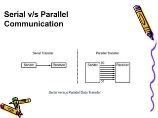
2. Serial v/s Parallel
Communication
Parallel Communication Serial Communication
Often 8 or more lines (wire
conductors) are used to transfer
data. Multiple bits are transferred at
a time.
The data is sent one bit at a time
on a single line (wire)
Preferred for short-distance
communication
Preferred over long-distance
communication
Costly as more resources are
required
Comparatively cheaper
Speed of data transfer is high Slow
Example: SPI, I2C, UART Example: PCI
3. Basics of Serial Communication
• Serial communication uses single data line making it much cheaper
• Enables two computers in different cities to communicate over the
telephone
• Byteof data must be converted to serial bits using a parallel-in-serial-
out shift register and transmitted over a single dataline
• At the receiving end there must be a serial-in-parallel-out shift
register
• Iftransferred on the telephone line, it must be converted to audio
tones by modem for short distance
5. Modes of Serial Communication
• In simplex transmissions, the computer can only send data. There is
only one wire.
• If the data can be transmitted and received, then it is a duplex
transmission
• Duplex transmissions can be half or full duplex depending on
whether or not the data transfer can besimultaneous
• Ifthe communication is only one way at a time, it is half duplex
• Ifboth sides can communicate at the same time, it is full duplex
Full duplex requires two wire conductors for the data lines
(in addition to the signalground)
6. Basics of Serial Communication
• Serial Communication can be
Asynchronous
Synchronous
Synchronous Communication
• Synchronous methods transfer a blockof data (characters) at a time
• The events are referenced to a clock
• Example: SPIbus, I2C bus
Asynchronous Communication
• Asynchronous methods transfer a single byte at a time
• There is no clock.The bytes are separated by start and stop bits.
• Example: UART
7. Basics of Serial Communication
• Tosupport serial communication, special interfaces are built in the
microcontroller.
• The microcontrollers use special ICchips called UART(universal
asynchronous receiver-transmitter) and USART(universal
synchronous asynchronous receiver-transmitter)
• 8051chip has a built-in UART
8. Data Framing in Asynchronous Serial
Communication
• Data is transmitted in 0s and 1s
• Tohave a sense of synchronization between transmitter and
receiver and to make sense of the data, transmitter and receiver
agree on a set of rules i.e protocol, which describes
how the data is packed
how many bits constitute a character
when the data begins and ends
9. Data Framing in Asynchronous Serial
Communication
Start and stop bits
• Each character is placed between start and stop bits. This is called
framing.
• Start bit is always one bit, stop bit can be one, two or one and half
bits
• In 8051serial port, when there is no transmission, the TxDline is
held high. This is called mark.
• Start bit is always a 0 (low), stop bit(s) is 1(high)
• LSBis sent out first
10. Data Framing in Asynchronous Serial
Communication
Framing ASCIIA
• The transmission begins with a start bit, followed bythe LSB(D0),
then the rest of the bits until MSB(D7), and finally, the one stop
bit indicating the end ofthe character
• When there is no transfer, the signal is 1(high), which isreferred
to as mark
11. TxD and RxD in 8051
• 8051has two pins that are used specificallyfor transferring and
receiving data serially
These two pins are called TxDand RxDand are part of the
port 3 group (P3.0 and P3.1)
These pins are TTLcompatible; therefore, they require a line
driver to make them RS232compatible
• Weneed a line driver (voltage converter) to convert the R232’s
signals to TTLvoltage levels that willbe acceptable to 8051’sTxD
and RxDpins
12. SCON Register
SM0 SM1 SM2 REN TB8 RB8 TI RI
SCON is an 8-bit register used to program the start bit, stop bit,
and data bits of data framing, among other Things
• SM0: Serial Mode Specifier
• SM1: Serial ModeSpeceifier
• SM2: Used for multiprocessor Communication
• REN: Set/Cleared bySoftware to enable/disable reception
• TB8: not used in Mode 1
• RB8: Not used in Mode 1
• TI: Transmit interrupt flag. Set byHWat the begin ofthe stop bit mode 1.
Andcleared by SW
• RI: Receiveinterrupt flag. Set byHWat the begin of the stop bit mode1.
Andcleared by SW
13. SCON Register
SM0, SM1 determine the framing of data by
specifying the number of bits per character, and the
start and stop bits
SM0 SM1 Serial Mode
0 0 Mode 0
0 1 Mode 1
1 0 Mode 2
1 1 Mode 3
14. Serial DataTransmission Modes
Mode0
• In this mode, the serial port works like a shift register and the
data transmission works synchronously with a clockfrequency of
fosc /12.
• Serial data is received and transmitted through RXD.
• 8 bits are transmitted/received at atime.
• Pin TXDoutputs the shift clockpulses of frequency fosc/12, which
is connected to the external circuitry for synchronization.
• The shift frequency or baud rate is always 1/12of the oscillator
frequency.
15. Serial DataTransmission Modes
Mode1
• In mode-1, the serial port functions as a standard Universal
Asynchronous ReceiverTransmitter (UART) mode.
• 10bits are transmitted through TXDor received through RXD.
• The 10 bits consist of one start bit (which is usually '0'), 8 data
bits (LSB is sent first/received first), and a stop bit (which is
usually '1').
• Once received, the stop bit goes into RB8 in the special function
register SCON.The baud rate isvariable.
TH1 = 256 - ((system frequency / (12 * 32)) / baud)
16. Serial DataTransmission Modes
Mode2
• In this mode 11-bits are transmitted through TXDor receivedthrough
RXD.
• The various bits are as follows: a start bit (usually '0'), 8 data bits (LSB
first), a programmable 9 th (TB8or RB8)bit and a stop bit (usually '1').
• While transmitting, the 9 th data bit (TB8in SCON)can be assigned the
value '0' or '1'.
For example, if the information ofparity is to be transmitted, the
parity bit (P) in PSWcould be moved into TB8.On reception ofthe
9th
data, the bit goes into RB8in 'SCON',while the stop bit is
ignored.
•
• The baud rate is programmable to either 1/32 or 1/64 of the oscillator
frequency.
fbaud = (2 SMOD /64) fosc.
17. Serial DataTransmission Modes
Mode3
• In this mode 11-bits are transmitted through TXDorreceived
through RXD.
• The various bits are: a start bit (usually '0'), 8 data bits (LSBfirst),
a programmable 9 th bit and a stop bit (usually'1').
• Mode-3is same as mode-2, except the fact that the baud rate in
mode-3 is variable (i.e., just as in mode-1).
• fbaud = (2 SMOD/32) * ( fosc/ 12(256-TH1)) .
• This baud rate holds when Timer-1is programmed in Mode-2.
18. Setting Baud rate in 8051
• Baud rate in the 8051baud rate in the 8051is programmable
Relationshipbetweenthecrystal frequencyandthebaudrate in
the 8051forTimer1usei.e;Mode1andMode3.
8051 divides the crystal frequency by 12 to get the machine cycle
frequency
XT
AL = 11.0592 MHz, the machine cycle frequency is 921.6 kHz
8051's UARTdivides the machine cycle frequency of 921.6 kHz by 32
once more before it is used by Timer 1to set the baud rate 921.6 kHz
divided by32 gives 28,800 Hz
19. Setting Baud rate in 8051
• Timer 1must be programmed in mode 2, that is 8-bit, auto-reload
20. Setting Baud rate in 8051
• Timer 1must be programmed in mode 2, that is 8-bit, auto-reload
21.
22. SBUF Register
• Abyte of data to be transferred via the TxDline must be placed in the
SBUFregister
• SBUFholds the byte of data when it is received bythe RxDline
• SBUFcan be accessed like any other register
MOVSBUF,#'D' ;load SBUF=44H,ASCIIfor'D‘
MOVSBUF,A
MOVA,SBUF
;copy accumulator into SBUF
;copy SBUF into accumulator
When a byte is written in SBUF, it is framed by 8051 with the start and
stop bits and transferred serially via the TxDpin
When the bits are received serially via RxD, it is deframed by 8051 by
eliminating the stop and start bits, making a byte out of the data received,
and then placing it in the SBUF
Framing need not be done by programmer explicitly
23. SBUF Register
• The special function register SBUFis physicallytwo registers.
One is, write-only and is used to hold data to be transmitted out
of the 8051via TXD.
The other is, read-only and holds the received data from external
sources via RXD.
• Both mutually exclusive registers have the same address 099H.
• SBUFis not bitaddressable
24. TI and RI Flags
TI(transmit interrupt)
• When 8051finishes the transfer of the 8-bit character, it raises the
TIflag to indicate that it is ready to transfer another byte
• TIbit is raised at the beginning of the stop bit
RI(receive interrupt)
• When the 8051 receives data serially via RxD, it places the byte in
the SBUFregister then raises the RI flag bit to indicate that a byte
has been received and should be picked up before it is lost
• RIis raised halfway through the stop bit
25. Programming the 8051 to transfer
character bytes serially
1. TMODregister is loaded with the value 20H, indicating the use of
timer 1in mode 2 (8-bit auto-reload) to set baudrate
2. The TH1is loaded with one of the value to set baud rate for serial data
transfer
3. The SCONregister is loaded with the value 50H, indicating serial mode
1,where an 8- bit data is framed with start and stopbits
4. TR1is set to 1to start timer1
5. TIis cleared by CLRTI instruction
6. The character byte to be transferred serially is written into
SBUF register
7. The TIflag bit is monitored with the use ofinstruction JNBTI,xxto see
if the character has been transferred completely
8. Totransfer the next byte, go to step 5
26. Steps that 8051 goes through in
transmitting a character via TxD
1. The byte character to be transmitted is written into the SBUFregister
2. The start bit is transferred
3. The 8-bit character is transferred on bit at a time
4. The stop bit is transferred
It is during the transfer ofthe stop bit that 8051raises the TIflag,
indicating that the last character was transmitted
5. Bymonitoring the TIflag, we make sure that we are not overloading
the SBUF
Ifwe write another byte into the SBUFbefore TIis raised, the
untransmitted portion ofthe previous byte will be lost
6. After SBUFis loaded with a new byte, the TIflag bit must be forced to
0 byCLRTIin order for this new byte to be transferred
27. Importance of TI Flag
• Bychecking the TIflag bit, we know whether or not the
8051is ready to transfer another byte
• Ifwe write a byte into SBUFbefore the TIflag bit is
raised, we risk the loss of a portion of the byte being
transferred
28. Programming the 8051 to
receive character bytes serially
1. TMODregister is loaded with the value 20H, indicating the use of
timer 1in mode 2 (8-bit auto-reload) to set baudrate
2. The TH1is loaded with one of the value to set baud rate for serial data
transfer
3. The SCONregister is loaded with the value 50H, indicating serial mode
1,where an 8- bit data is framed with start and stopbits
4. TR1is set to 1to start timer1
5. RIis cleared by CLRRIinstruction
6. The RIflag bit is monitored with the use of instruction JNBRI,xxto see
if the entire character has been received yet
7. When RIis raised, SBUFhas the byte, its contents are moved into a
safe place
8. Totransfer the next byte, go to step 5
29. Steps that 8051 goes through in
receiving a character via RxD
1. It receives the start bit
Indicating that the next bit is the first bit of the character byte it is about
to receive
2. The 8-bit character is received one bit at time
3. The stop bit is received
When receiving the stop bit 8051 makes RI = 1, indicating that an entire
character byte has been received and must be picked up before it gets
overwritten by an incoming character
4. By checking the RI flag bit when it is raised, we know that a character has
been received and is sitting in the SBUFregister
We copy the SBUF contents to a safe place in some other register or
memory before it is lost
5. After the SBUF contents are copied into a safe place, the RI flag bit must be
forced to 0 by CLR RI in order to allow the next received character byte to be
placed in SBUF
Failure to do this causes loss ofthe receivedcharacter
30. Importance of RI Flag
• Bychecking the RIflag bit, we know whether or not the
8051received a character byte
• Ifwe copySBUFinto a safe place before the RIflag bit is
raised, we risk copying garbage
31. Steps that 8051 goes through in
receiving a character via RxD
1. It receives the start bit
Indicating that the next bit is the first bit of the character byte it is about
to receive
2. The 8-bit character is received one bit at time
3. The stop bit is received
When receiving the stop bit 8051 makes RI = 1, indicating that an entire
character byte has been received and must be picked up before it gets
overwritten by an incoming character
4. By checking the RI flag bit when it is raised, we know that a character has
been received and is sitting in the SBUFregister
We copy the SBUF contents to a safe place in some other register or
memory before it is lost
5. After the SBUF contents are copied into a safe place, the RI flag bit must be
forced to 0 by CLR RI in order to allow the next received character byte to be
placed in SBUF
Failure to do this causes loss ofthe receivedcharacter
32. Note: No need to use timers in case of Mode-0 and Mode-2 operation of
serial communication since timers do not control the baud rate.
33.
34.
35. Doubling the Baud Rate in 8051
• There are two ways to increase the baud rate ofdata transfer
Touse a higher frequency crystal
Toset the SMODbit in the PCONregister
• PCONregister is an 8-bit register, whose MSBisSMOD
• When 8051is powered up, SMODis zero
• Wecan set it to high bysoftware and thereby double the baud rate
• PCONis not bit-addressable register. Hence, we cannot set SMOD
bit directly. This may be done as:
MOVA,PCON
SETBACC.7
MOVPCON,A
;place a copy of PCONinACC
;make D7=1
;changing any other bits
37. 8051 Interrupts
An interrupt is an external or internal event that disturbs
the microcontroller to inform it that a device needs its
service.
A Microcontroller can serve various devices.
There are two ways to do that:
interrupts &
polling.
The program which is associated with the interrupt is
called the interrupt service routine (ISR) or
interrupt handler.
38. Steps in executing an interrupt
Upon receiving the interrupt signal the
Microcontroller , finish current instruction
and saves the PC on stack.
Jumps to a fixed location in memory depending
on type of interrupt
Starts to execute the interrupt service
routine until RETI (return from interrupt)
Upon executing the RETI the microcontroller
returns to the place where it was interrupted.
Get pop PC from stack
39. Interrupt Sources
Original 8051 has 6 sources of
interrupts
Reset
Timer 0 overflow
Timer 1 overflow
External Interrupt 0
External Interrupt 1
Serial Port events (buffer full, buffer empty, etc)
Enhanced version has 22 sources
More timers, programmable counter array, ADC,
more external interrupts, another serial port (UART)
40. Each interrupt has a specific place in code
memory where program execution
(interrupt service routine) begins.
External Interrupt 0: 0003h
000Bh
0013h
001Bh
Timer 0 overflow:
External Interrupt 1:
Timer 1 overflow:
Serial : 0023h
Timer 2 overflow(8052+) 002bh
Interrupt Vectors
41. Interrupt Enable Register
Upon reset all Interrupts are disabled & do
not respond to the Microcontroller
These interrupts must be enabled by software
in order for the Microcontroller to respond to
them.
This is done by an 8-bit register called
Interrupt Enable Register (IE).
43. Enabling and disabling an
interrupt
By bit operation
Recommended in the middle of program
SETB EA
SETB ET0
;Enable All
;Enable Timer0 ovrf
SETB ET1
SETB EX0
SETB EX1
SETB ES
;Enable Timer1 ovrf
;Enable INT0
;Enable INT1
;Enable Serial port
By Mov instruction
Recommended in the first of program
MOV IE, #10010110B
SETB
SETB
IE.7
IE.1
SETB
SETB
SETB
IE.3
IE.0
IE.2
SETB IE.4
44.
What if two interrupt sources interrupt at the same
time?
The interrupt with the highest PRIORITY gets
serviced first.
All interrupts have a power on default priority order.
1. External interrupt 0 (INT0)
2. Timer interrupt0 (TF0)
3. External interrupt 1 (INT1)
4. Timer interrupt1 (TF1)
5. Serial communication (RI+TI)
Priority can also be set to “high” or “low” by IP reg.
Interrupt Priorities
45. Interrupt Priorities (IP) Register
IP.7: reserved
IP.6: reserved
IP.5: Timer 2 interrupt priority bit (8052 only)
IP.4: Serial port interrupt priority bit
IP.3: Timer 1 interrupt priority bit
IP.2: External interrupt 1 priority bit
IP.1: Timer 0 interrupt priority bit
IP.0: External interrupt 0 priority bit
--- PX0
PT2 PS PT1 PX1 PT0
---
46. Interrupt Priorities Example
MOV IP , #00000100B or SETB IP.2 gives priority
order
1. Int1
2. Int0
3. Timer0
4. Timer1
5. Serial
MOV IP , #00001100B gives priorityorder
1. Int1
2. Timer1
3. Int0
4. Timer0
5. Serial
--- PX0
PT2 PS PT1 PX1 PT0
---
47. Interrupt inside an interrupt
--- PX0
PT2 PS PT1 PX1 PT0
---
A high-priority interrupt can interrupt a
low-
priority interrupy
All interrupt are latched internally
Low-priority interrupt wait until 8051 has
finished servicing the high-priority
interrupt