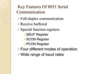
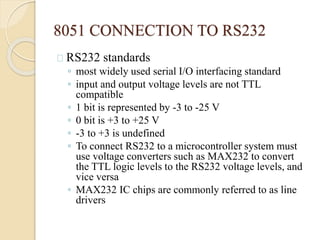
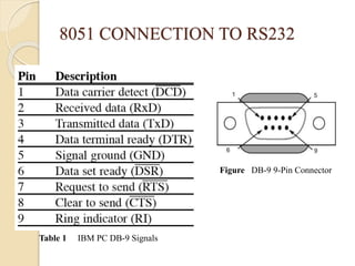
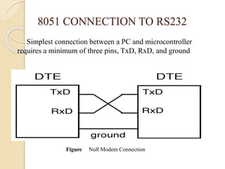
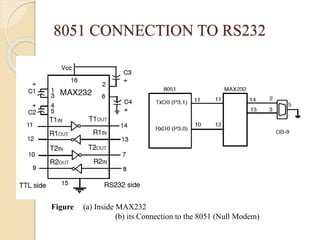
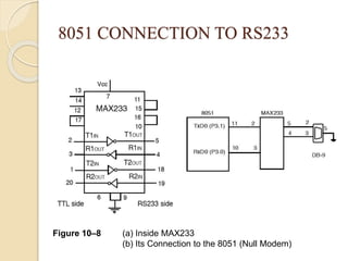
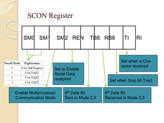
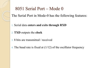
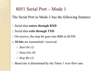
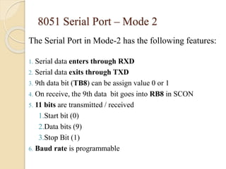
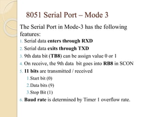
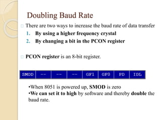
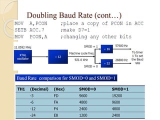
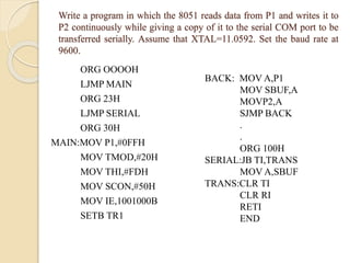
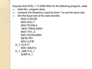
2. OUTLINE
Key features of 8051 Serial Communication
8051 connection to RS232
Four different modes of operation
Doubling baud rate
Programs
3. Key Features Of 8051 Serial
Communication
Full-duplex communication
Receive buffered
Special function registers
SBUF Register
SCON Register
PCON Register
Four different modes of operation
Wide range of baud rates
4. 8051 CONNECTION TO RS232
RS232 standards
◦ most widely used serial I/O interfacing standard
◦ input and output voltage levels are not TTL
compatible
◦ 1 bit is represented by -3 to -25 V
◦ 0 bit is +3 to +25 V
◦ -3 to +3 is undefined
◦ To connect RS232 to a microcontroller system must
use voltage converters such as MAX232 to convert
the TTL logic levels to the RS232 voltage levels, and
vice versa
◦ MAX232 IC chips are commonly referred to as line
drivers
5. 8051 CONNECTION TO RS232
Figure DB-9 9-Pin Connector
Table 1 IBM PC DB-9 Signals
6. 8051 CONNECTION TO RS232
Simplest connection between a PC and microcontroller
requires a minimum of three pins, TxD, RxD, and ground
Figure Null Modem Connection
7. 8051 CONNECTION TO RS232
RxD and TxD pins in the 8051
◦ 8051 has two pins used for transferring and receiving
data serially
◦ TxD and RxD are part of the port 3 group
◦ pin 11 (P3.1) is assigned to TxD
◦ pin 10 (P3.0) is designated as RxD
◦ these pins are TTL compatible
◦ require a line driver to make them RS232 compatible
◦ driver is the MAX232 chip
8. 8051 CONNECTION TO RS232
MAX232
◦ converts from RS232 voltage levels to TTL
voltage levels
◦ uses a +5 V power source
◦ MAX232 has two sets of line drivers for
transferring and receiving data
◦ line drivers used for TxD are called T1 and T2
◦ line drivers for RxD are designated as R1 and R2
◦ T1 and R1 are used together for TxD and RxD of
the 8051
◦ second set is left unused
9. 8051 CONNECTION TO RS232
Figure (a) Inside MAX232
(b) its Connection to the 8051 (Null Modem)
10. 8051 CONNECTION TO RS232
MAX233
◦ MAX233 performs the same job as the MAX232
◦ eliminates the need for capacitors
◦ much more expensive than the MAX232
11. 8051 CONNECTION TO RS233
Figure 10–8 (a) Inside MAX233
(b) Its Connection to the 8051 (Null Modem)
12. SCON Register
SM0 SM1 SM2 REN TB8 RB8 TI RI
Set to Enable
Serial Data
reception
Enable Multiprocessor
Communication Mode
9th Data Bit
Sent in Mode 2,3
Set when a Cha-ractor
received
Set when Stop bit Txed
9th Data Bit
Received in Mode 2,3
13. 8051 Serial Port – Mode 0
The Serial Port in Mode-0 has the following features:
1. Serial data enters and exits through RXD
2. TXD outputs the clock
3. 8 bits are transmitted / received
4. The baud rate is fixed at (1/12) of the oscillator frequency
14. 8051 Serial Port – Mode 1
The Serial Port in Mode-1 has the following features:
1. Serial data enters through RXD
2. Serial data exits through TXD
3. On receive, the stop bit goes into RB8 in SCON
4. 10 bits are transmitted / received
1. Start bit (1)
2. Data bits (8)
3. Stop Bit (1)
5. Baud rate is determined by the Timer 1 over flow rate.
15. 8051 Serial Port – Mode 2
The Serial Port in Mode-2 has the following features:
1. Serial data enters through RXD
2. Serial data exits through TXD
3. 9th data bit (TB8) can be assign value 0 or 1
4. On receive, the 9th data bit goes into RB8 in SCON
5. 11 bits are transmitted / received
1.Start bit (0)
2.Data bits (9)
3.Stop Bit (1)
6. Baud rate is programmable
16. 8051 Serial Port – Mode 3
The Serial Port in Mode-3 has the following
features:
1. Serial data enters through RXD
2. Serial data exits through TXD
3. 9th data bit (TB8) can be assign value 0 or 1
4. On receive, the 9th data bit goes into RB8 in SCON
5. 11 bits are transmitted / received
1.Start bit (0)
2.Data bits (9)
3.Stop Bit (1)
6. Baud rate is determined by Timer 1 overflow rate.
17. Doubling Baud Rate
There are two ways to increase the baud rate of data transfer
1. By using a higher frequency crystal
2. By changing a bit in the PCON register
PCON register is an 8-bit register.
•When 8051 is powered up, SMOD is zero
•We can set it to high by software and thereby double the
baud rate.
19. Write a program in which the 8051 reads data from P1 and writes it to
P2 continuously while giving a copy of it to the serial COM port to be
transferred serially. Assume that XTAL=11.0592. Set the baud rate at
9600.
ORG OOOOH
LJMP MAIN
ORG 23H
LJMP SERIAL
ORG 30H
MAIN:MOV P1,#0FFH
MOV TMOD,#20H
MOV THI,#FDH
MOV SCON,#50H
MOV IE,1001000B
SETB TR1
BACK: MOV A,P1
MOV SBUF,A
MOVP2,A
SJMP BACK
.
.
ORG 100H
SERIAL:JB TI,TRANS
MOV A,SBUF
TRANS:CLR TI
CLR RI
RETI
END
20. Assume that XTAL = 11.0592 MHz for the following program, state
(a) what this program does,
(b) compute the frequency used by timer 1 to set the baud rate,
(c) find the baud rate of the data transfer.
MOV A,PCON
MOV ACC.7
MOV PCON,A
MOV TMOD,#20H
MOV TH1,-3
MOV SCON,#50H
SETB TR1
MOV A,#”B”
A_1: CLR TI
MOV SBUF,A
H_1: JNB TI,H_1
SJMP A_1
21. Solution:
(a) This program transfers ASCII letter B (01000010
binary) continuously
(b) With XTAL = 11.0592 MHz and SMOD = 1 in the
above program, we have: 11.0592 / 12 = 921.6 kHz
machine cycle frequency.
(c)921.6 / 16 = 57,600 Hz frequency used by timer 1 to set
the baud rate. 57600 / 3 = 19,200, the baud rate.
22. CONCLUSION
In this lecture we had seen how serial
communication of 8051 operates in four
different modes among the four modes mode1 is
normally used to communicate with the
conventional computer using RS232 rather than
mode2 and mode3 can be used to multiprocessor
communication.