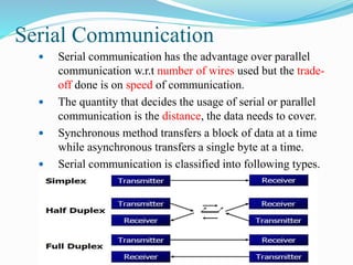
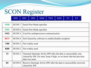
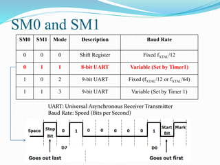
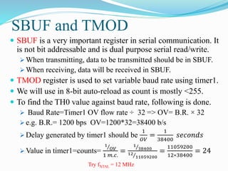
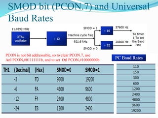
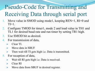
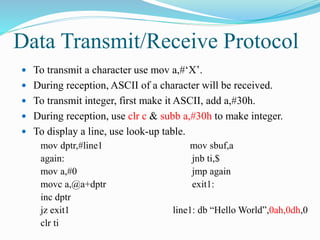
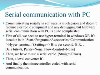
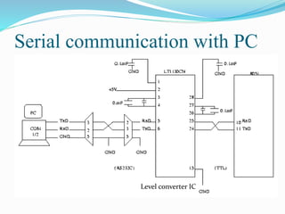
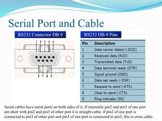
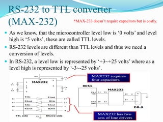
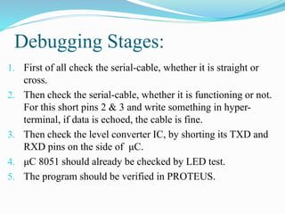
COMMUNICATING WITH PC USING SERIAL
COMMUNICATION IN 8051
Objectives of the Lab
 Serial Communication Types
 Registers governing Serial communication
 Using timer1 to set baud rate
 Hardware necessities for serial communication
Deciding Pins or Ports to use
Use with
caution
If EA high
*The pins for this
purpose are by
default P3.0(RXD)
and P3.1(TXD) .
Serial Communication
 Serial communication has the advantage over parallel
communication w.r.t number of wires used but the trade-
off done is on speed of communication.
 The quantity that decides the usage of serial or parallel
communication is the distance, the data needs to cover.
 Synchronous method transfers a block of data at a time
while asynchronous transfers a single byte at a time.
 Serial communication is classified into following types.
SCON Register
SM0 SCON.7 Serial Port Mode specifier
SM1 SCON.6 Serial Port Mode specifier
SM2 SCON.5 Used for multiprocessor communication
REN SCON.4 Set/Cleared by software to enable/disable reception
TB8 SCON.3 Not widely used
RB8 SCON.2 Not widely used
TI SCON.1 Transmit Interrupt, Set by HW after the data is successfully sent,
cleared by SW. (At start, keep it high, so we know that the previous
data was sent)
RI SCON.0 Receive Interrupt, Set by HW after the data is successfully received,
cleared by SW.
SM0 and SM1
SM0 SM1 Mode Description Baud Rate
0 0 0 Shift Register Fixed fXTAL/12
0 1 1 8-bit UART Variable (Set by Timer1)
1 0 2 9-bit UART Fixed (fXTAL/12 or fXTAL/64)
1 1 3 9-bit UART Variable (Set by Timer 1)
UART: Universal Asynchronous Receiver Transmitter
Baud Rate: Speed (Bits per Second)
SBUF and TMOD
 SBUF is a very important register in serial communication. It
is not bit addressable and is dual purpose serial read/write.
 When transmitting, data to be transmitted should be in SBUF.
 When receiving, data will be received in SBUF.
 TMOD register is used to set variable baud rate using timer1.
 We will use in 8-bit auto-reload as count is mostly <255.
 To find the TH0 value against baud rate, following is done.
 Baud Rate=Timer1 OV flow rate ÷ 32 => OV= B.R. × 32
 e.g. B.R.= 1200 bps OV=1200*32=38400 b/s
 Delay generated by timer1 should be
1
𝑂𝑉
=
1
38400
𝑠𝑒𝑐𝑜𝑛𝑑𝑠
 Value in timer1=counts=
1
𝑂𝑉
1 𝑚.𝑐.
=
1
38400
12
11059200
=
11059200
12∗38400
= 24
Try fXTAL = 12 MHz
SMOD bit (PCON.7) and Universal
Baud Rates
PCON is not bit addressable, so to clear PCON.7, use
Anl PCON,#01111111b, and to set Orl PCON,#10000000b
Pseudo-Code for Transmitting and
Receiving Data through serial port
1. Move value in SMOD using mode1, keeping REN=1, RI=0 and
TI=1.
2. Configure TMOD for timer1, mode 2 and load value in TH1 and
TL1 for desired baud rate and run timer by setting TR1 high.
3. Use SMOD bit as desired.
4. For transmission of data,
 Clear TI.
 Move data in SBUF
 Then wait till TI gets high i.e. Data is transmitted.
5. For reception of data,
 Wait till RI gets high i.e. Data is received.
 Clear RI
 Move data from SBUF in desired register.
Data Transmit/Receive Protocol
 To transmit a character use mov a,#‘X’.
 During reception, ASCII of a character will be received.
 To transmit integer, first make it ASCII, add a,#30h.
 During reception, use clr c & subb a,#30h to make integer.
 To display a line, use look-up table.
mov dptr,#line1
again:
mov a,#0
movc a,@a+dptr
inc dptr
jz exit1
clr ti
mov sbuf,a
jnb ti,$
jmp again
exit1:
line1: db “Hello World”,0ah,0dh,0
Proteus Devices needed in this Lab
1. AT89c51
2. Virtual Terminal (TXD, RXD, use in cross-connection)
Virtual Terminal Settings:
Baud Rate= as desired. Rest settings as default
Serial communication with PC
 Communicating serially in software is much easier and doesn’t
require electronic equipment and any debugging but hardware
serial communication with PC is quite complicated.
 First of all, we need to use hyper-terminal in windows XP. It’s
location is in ‘Start>Programs>Accessories>Communication
>Hyper-terminal.’ (Settings=> Bits per second: B.R. ,
Data bits=8, Parity=None, Flow-Control=None)
 Then, we have to use a serial cable. (Straight/Cross)
 Then, a level converter IC.
 And finally the microcontroller coded with serial
communication.
Serial communication with PC
Level converter IC
Serial Port and Cable
Serial cables have serial ports on both sides of it. If internally pin2 and pin3 of one port
are short with pin2 and pin3 of other port it is straight cable, if pin2 of one port is
connected to pin3 of other port and pin3 of one port is connected to pin2, this is cross cable.
RS-232 to TTL converter
(MAX-232)
 As we know, that the microcontroller level low is ‘0 volts’ and level
high is ‘5 volts’, these are called TTL levels.
 RS-232 levels are different than TTL levels and thus we need a
conversion of levels.
 In RS-232, a level low is represented by ‘+3~+25 volts’ where as a
level high is represented by ‘-3~-25 volts’.
*MAX-233 doesn’t require capacitors but is costly.
Debugging Stages:
1. First of all check the serial-cable, whether it is straight or
cross.
2. Then check the serial-cable, whether it is functioning or not.
For this short pins 2 & 3 and write something in hyper-
terminal, if data is echoed, the cable is fine.
3. Then check the level converter IC, by shorting its TXD and
RXD pins on the side of μC.
4. μC 8051 should already be checked by LED test.
5. The program should be verified in PROTEUS.
Final Remark on μC 8051 LAB:
Small Size, Low-Cost, Same
Function: AT89C2051
Lab Tasks
 Serially communicate with PC. If key pressed is that of
your workstation number then display ‘Workstation#xy’
otherwise display ‘Invalid input’.
 Quiz Next Week of Timers.
1. Last Week Submissions: Project SW, HW and Report
(ADC0804 submission)
2. Vivas from Project and μC Lab
3. Lab Manual Submission

Micro c lab8(serial communication)

  • 1.
    COMMUNICATING WITH PCUSING SERIAL COMMUNICATION IN 8051
  • 2.
    Objectives of theLab  Serial Communication Types  Registers governing Serial communication  Using timer1 to set baud rate  Hardware necessities for serial communication
  • 3.
    Deciding Pins orPorts to use Use with caution If EA high *The pins for this purpose are by default P3.0(RXD) and P3.1(TXD) .
  • 4.
    Serial Communication  Serialcommunication has the advantage over parallel communication w.r.t number of wires used but the trade- off done is on speed of communication.  The quantity that decides the usage of serial or parallel communication is the distance, the data needs to cover.  Synchronous method transfers a block of data at a time while asynchronous transfers a single byte at a time.  Serial communication is classified into following types.
  • 5.
    SCON Register SM0 SCON.7Serial Port Mode specifier SM1 SCON.6 Serial Port Mode specifier SM2 SCON.5 Used for multiprocessor communication REN SCON.4 Set/Cleared by software to enable/disable reception TB8 SCON.3 Not widely used RB8 SCON.2 Not widely used TI SCON.1 Transmit Interrupt, Set by HW after the data is successfully sent, cleared by SW. (At start, keep it high, so we know that the previous data was sent) RI SCON.0 Receive Interrupt, Set by HW after the data is successfully received, cleared by SW.
  • 6.
    SM0 and SM1 SM0SM1 Mode Description Baud Rate 0 0 0 Shift Register Fixed fXTAL/12 0 1 1 8-bit UART Variable (Set by Timer1) 1 0 2 9-bit UART Fixed (fXTAL/12 or fXTAL/64) 1 1 3 9-bit UART Variable (Set by Timer 1) UART: Universal Asynchronous Receiver Transmitter Baud Rate: Speed (Bits per Second)
  • 7.
    SBUF and TMOD SBUF is a very important register in serial communication. It is not bit addressable and is dual purpose serial read/write.  When transmitting, data to be transmitted should be in SBUF.  When receiving, data will be received in SBUF.  TMOD register is used to set variable baud rate using timer1.  We will use in 8-bit auto-reload as count is mostly <255.  To find the TH0 value against baud rate, following is done.  Baud Rate=Timer1 OV flow rate ÷ 32 => OV= B.R. × 32  e.g. B.R.= 1200 bps OV=1200*32=38400 b/s  Delay generated by timer1 should be 1 𝑂𝑉 = 1 38400 𝑠𝑒𝑐𝑜𝑛𝑑𝑠  Value in timer1=counts= 1 𝑂𝑉 1 𝑚.𝑐. = 1 38400 12 11059200 = 11059200 12∗38400 = 24 Try fXTAL = 12 MHz
  • 8.
    SMOD bit (PCON.7)and Universal Baud Rates PCON is not bit addressable, so to clear PCON.7, use Anl PCON,#01111111b, and to set Orl PCON,#10000000b
  • 9.
    Pseudo-Code for Transmittingand Receiving Data through serial port 1. Move value in SMOD using mode1, keeping REN=1, RI=0 and TI=1. 2. Configure TMOD for timer1, mode 2 and load value in TH1 and TL1 for desired baud rate and run timer by setting TR1 high. 3. Use SMOD bit as desired. 4. For transmission of data,  Clear TI.  Move data in SBUF  Then wait till TI gets high i.e. Data is transmitted. 5. For reception of data,  Wait till RI gets high i.e. Data is received.  Clear RI  Move data from SBUF in desired register.
  • 10.
    Data Transmit/Receive Protocol To transmit a character use mov a,#‘X’.  During reception, ASCII of a character will be received.  To transmit integer, first make it ASCII, add a,#30h.  During reception, use clr c & subb a,#30h to make integer.  To display a line, use look-up table. mov dptr,#line1 again: mov a,#0 movc a,@a+dptr inc dptr jz exit1 clr ti mov sbuf,a jnb ti,$ jmp again exit1: line1: db “Hello World”,0ah,0dh,0
  • 11.
    Proteus Devices neededin this Lab 1. AT89c51 2. Virtual Terminal (TXD, RXD, use in cross-connection) Virtual Terminal Settings: Baud Rate= as desired. Rest settings as default
  • 12.
    Serial communication withPC  Communicating serially in software is much easier and doesn’t require electronic equipment and any debugging but hardware serial communication with PC is quite complicated.  First of all, we need to use hyper-terminal in windows XP. It’s location is in ‘Start>Programs>Accessories>Communication >Hyper-terminal.’ (Settings=> Bits per second: B.R. , Data bits=8, Parity=None, Flow-Control=None)  Then, we have to use a serial cable. (Straight/Cross)  Then, a level converter IC.  And finally the microcontroller coded with serial communication.
  • 13.
    Serial communication withPC Level converter IC
  • 14.
    Serial Port andCable Serial cables have serial ports on both sides of it. If internally pin2 and pin3 of one port are short with pin2 and pin3 of other port it is straight cable, if pin2 of one port is connected to pin3 of other port and pin3 of one port is connected to pin2, this is cross cable.
  • 15.
    RS-232 to TTLconverter (MAX-232)  As we know, that the microcontroller level low is ‘0 volts’ and level high is ‘5 volts’, these are called TTL levels.  RS-232 levels are different than TTL levels and thus we need a conversion of levels.  In RS-232, a level low is represented by ‘+3~+25 volts’ where as a level high is represented by ‘-3~-25 volts’. *MAX-233 doesn’t require capacitors but is costly.
  • 16.
    Debugging Stages: 1. Firstof all check the serial-cable, whether it is straight or cross. 2. Then check the serial-cable, whether it is functioning or not. For this short pins 2 & 3 and write something in hyper- terminal, if data is echoed, the cable is fine. 3. Then check the level converter IC, by shorting its TXD and RXD pins on the side of μC. 4. μC 8051 should already be checked by LED test. 5. The program should be verified in PROTEUS.
  • 17.
    Final Remark onμC 8051 LAB: Small Size, Low-Cost, Same Function: AT89C2051
  • 18.
    Lab Tasks  Seriallycommunicate with PC. If key pressed is that of your workstation number then display ‘Workstation#xy’ otherwise display ‘Invalid input’.  Quiz Next Week of Timers. 1. Last Week Submissions: Project SW, HW and Report (ADC0804 submission) 2. Vivas from Project and μC Lab 3. Lab Manual Submission