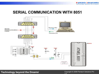
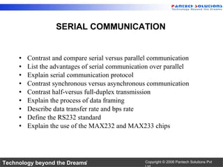
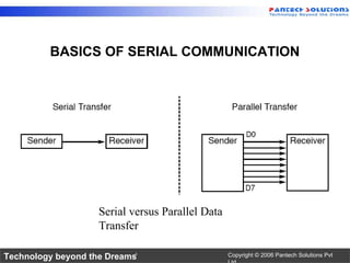
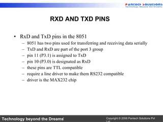
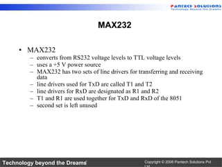
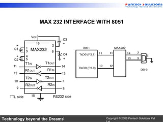
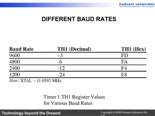
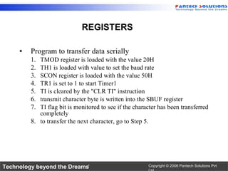
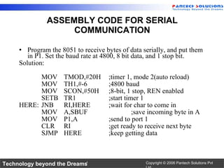
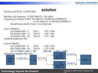
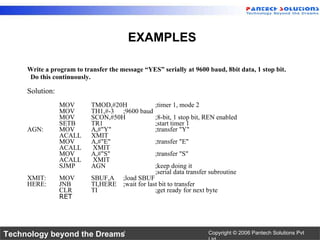
8051 Serial Communication-UART www.pantechsolutions.net
SERIAL COMMUNICATION WITH 8051
SERIAL COMMUNICATION Contrast and compare serial versus parallel communication List the advantages of serial communication over parallel Explain serial communication protocol Contrast synchronous versus asynchronous communication Contrast half-versus full-duplex transmission Explain the process of data framing Describe data transfer rate and bps rate Define the RS232 standard Explain the use of the MAX232 and MAX233 chips
BASICS OF SERIAL COMMUNICATION Serial versus Parallel Data Transfer
SERIAL COMMUNICATION Byte of data must be converted to serial bits using a parallel-in-serial-out shift register and transmitted over a single data line receiving end there must be a serial-in-parallel-out shift register if transferred on the telephone line, it must be converted to audio tones by  modem   for short distance the signal can be transferred using wire how PC keyboards transfer data to the motherboard  2 methods, asynchronous and synchronous synchronous  method transfers a block of data (characters) at a time asynchronous  method transfers a single byte at a time Uses special IC chips called UART (universal asynchronous receiver-transmitter) and USART (universal synchronous asynchronous receiver-transmitter) 8051 chip has a built-in UART
METHODS OF COMMUNICATION
DIFFERENT TYPES OF TRANSMISSION Half- and full-duplex transmission if the data can be transmitted and received, it is a  duplex  transmission simplex  transmissions the computer only sends data duplex transmissions can be half or full duplex depends on whether or not the data transfer can be simultaneous If one way at a time, it is  half duplex If can go both ways at the same time, it is full duplex full duplex requires two wire conductors for the data lines (in addition to the signal ground)
SERIAL COMMUNICATION Framing ASCII “A” (41H)
Data transfer rate rate of data transfer  bps  (bits per second) widely used terminology for bps is  baud rate baud and bps rates are not necessarily equal baud rate is defined as the number of signal changes per second Baud rate in the 8051 serial communications of the 8051 with the COM port of the PC must make sure that the baud rate of the 8051 system matches the baud rate of the PC's COM port can use Windows HyperTerminal program BAUD RATE
RS232 standards most widely used serial I/O interfacing standard input and output voltage levels are not TTL compatible 1 bit is represented by -3 to -25 V 0 bit is +3 to +25 V -3 to +3 is undefined to connect RS232 to a microcontroller system must use voltage converters such as MAX232 to convert the TTL logic levels to the RS232 voltage levels, and vice versa MAX232 IC chips are commonly referred to as line drivers  RS232 PIN VOLTAGE DETAILS
PIN DESCRIPTION DB-9 9-Pin Connector IBM PC DB-9 Signals
Data communication classification DTE (data terminal equipment)  DCE (data communication equipment) DTE - terminals and computers that send and receive data DCE - communication equipment responsible for transferring the data simplest connection between a PC and microcontroller requires a minimum of three pins, TxD, RxD, and ground DATA COMMUNICATION
RxD and TxD pins in the 8051 8051 has two pins used for transferring and receiving data serially TxD and RxD are part of the port 3 group  pin 11 (P3.1) is assigned to TxD pin 10 (P3.0) is designated as RxD these pins are TTL compatible require a line driver to make them RS232 compatible driver is the MAX232 chip  RXD AND TXD PINS
MAX232 converts from RS232 voltage levels to TTL voltage levels uses a +5 V power source MAX232 has two sets of line drivers for transferring and receiving data line drivers used for TxD are called T1 and T2 line drivers for RxD are designated as R1 and R2 T1 and R1 are used together for TxD and RxD of the 8051 second set is left unused MAX232
MAX 232 INTERFACE WITH 8051
DIFFERENT BAUD RATES Timer 1 TH1 Register Values for Various Baud Rates
Program to transfer data serially TMOD register is loaded with the value 20H TH1 is loaded with value to set the baud rate SCON register is loaded with the value 50H TR1 is set to 1 to start Timer1 TI is cleared by the "CLR TI" instruction transmit character byte is written into the SBUF register TI flag bit is monitored to see if the character has been transferred completely to transfer the next character, go to Step 5. REGISTERS
Program the 8051 to receive bytes of data serially, and put them in P1. Set the baud rate at 4800, 8 bit data, and 1 stop bit. Solution: MOV TMOD,#20H ;timer 1, mode 2(auto reload) MOV TH1,#-6 ;4800 baud MOV SCON,#50H ;8-bit, 1 stop, REN enabled SETB TR1 ;start timer 1 HERE: JNB RI,HERE ;wait for char to come in MOV A,SBUF ;save incoming byte in A MOV P1,A ;send to port 1 CLR RI ;get ready to receive next byte SJMP HERE ;keep getting data ASSEMBLY CODE FOR SERIAL COMMUNICATION
s solution Solution:with XTAL=11.0592 MHz: Machine cycle frequency: 11.0592 MHz/12 = 921.6kHz,  Frequency provided by UART: 921.6kHz/32 =28,800 Hz (if SMOD=0) or  921.6kHz/16 =57,600 Hz (if SMOD=1) should be provided by Timer 1 to set baud rate. Case I: SMOD=0. (a) 28,800/9,600 = 3.  256-3 = 253 = FDh (b) 28,800/2,400 = 12. 256-12 = 244 = F4h (c) 28,800/1,200 = 24. 256-24  = 232 = E8h should be loaded into TH1. Case II: SMOD=1. (a) 57,600/9,600 = 6.  256-6 = 250 = FAh (b) 57,600/2,400 = 24. 256-24 = 232 = E8h (c) 57,600/1,200 = 48. 256-48  = 232 = D0h should be loaded into TH1. XTAL OSC ÷ 12 ÷ 32 by UART (SMOD=0) 11.0592 MHz 28,800 Hz 921.6 kHz ÷ 16 by UART (SMOD=1) 57,600 Hz Timer 1
Write a program to transfer the message “YES” serially at 9600 baud, 8bit data, 1 stop bit.  Do this continuously.  Solution: MOV TMOD,#20H ;timer 1, mode 2 MOV TH1,#-3 ;9600 baud MOV SCON,#50H ;8-bit, 1 stop bit, REN enabled SETB TR1 ;start timer 1 AGN: MOV A,#"Y" ;transfer "Y" ACALL XMIT MOV A,#"E" ;transfer "E" ACALL  XMIT MOV A,#"S" ;transfer "S" ACALL  XMIT SJMP AGN ;keep doing it ;serial data transfer subroutine XMIT: MOV SBUF,A ;load SBUF HERE: JNB TI,HERE ;wait for last bit to transfer CLR TI ;get ready for next byte RET EXAMPLES
#include <REG51.H>  /* special function register declarations  */ #include <stdio.h>  /* prototype declarations for I/O functions */ void serial_init(void); void serial_init(void) { SCON  = 0x50; /* SCON: mode 1, 8-bit UART, enable rcvr  */ TMOD |= 0x20;  /* TMOD: timer 1, mode 2, 8-bit reload  */ TH1  = 0xFD;  /* TH1:  reload value for 9600 baud @ 11.0592MHz*/ TR1  = 1;    /* TR1:  timer 1 run  */ TI  = 1;  void main(void) { serial_init(); printf (&quot; PS - PrimerC51 UART Demo\n\n\r&quot;); while (1)  { printf (&quot;Hello World!! \n\r&quot;);  /* Print &quot;Hello World&quot; */ } } C CODE FOR SERIAL COMMUNICATION
For More Tutorials www.pantechsolutions.net http://www.slideshare.net/pantechsolutions http://www.scribd.com/pantechsolutions http://www.youtube.com/pantechsolutions

8051 serial communication-UART

  • 1.
    8051 Serial Communication-UARTwww.pantechsolutions.net
  • 2.
  • 3.
    SERIAL COMMUNICATION Contrastand compare serial versus parallel communication List the advantages of serial communication over parallel Explain serial communication protocol Contrast synchronous versus asynchronous communication Contrast half-versus full-duplex transmission Explain the process of data framing Describe data transfer rate and bps rate Define the RS232 standard Explain the use of the MAX232 and MAX233 chips
  • 4.
    BASICS OF SERIALCOMMUNICATION Serial versus Parallel Data Transfer
  • 5.
    SERIAL COMMUNICATION Byteof data must be converted to serial bits using a parallel-in-serial-out shift register and transmitted over a single data line receiving end there must be a serial-in-parallel-out shift register if transferred on the telephone line, it must be converted to audio tones by modem for short distance the signal can be transferred using wire how PC keyboards transfer data to the motherboard 2 methods, asynchronous and synchronous synchronous method transfers a block of data (characters) at a time asynchronous method transfers a single byte at a time Uses special IC chips called UART (universal asynchronous receiver-transmitter) and USART (universal synchronous asynchronous receiver-transmitter) 8051 chip has a built-in UART
  • 6.
  • 7.
    DIFFERENT TYPES OFTRANSMISSION Half- and full-duplex transmission if the data can be transmitted and received, it is a duplex transmission simplex transmissions the computer only sends data duplex transmissions can be half or full duplex depends on whether or not the data transfer can be simultaneous If one way at a time, it is half duplex If can go both ways at the same time, it is full duplex full duplex requires two wire conductors for the data lines (in addition to the signal ground)
  • 8.
    SERIAL COMMUNICATION FramingASCII “A” (41H)
  • 9.
    Data transfer raterate of data transfer bps (bits per second) widely used terminology for bps is baud rate baud and bps rates are not necessarily equal baud rate is defined as the number of signal changes per second Baud rate in the 8051 serial communications of the 8051 with the COM port of the PC must make sure that the baud rate of the 8051 system matches the baud rate of the PC's COM port can use Windows HyperTerminal program BAUD RATE
  • 10.
    RS232 standards mostwidely used serial I/O interfacing standard input and output voltage levels are not TTL compatible 1 bit is represented by -3 to -25 V 0 bit is +3 to +25 V -3 to +3 is undefined to connect RS232 to a microcontroller system must use voltage converters such as MAX232 to convert the TTL logic levels to the RS232 voltage levels, and vice versa MAX232 IC chips are commonly referred to as line drivers RS232 PIN VOLTAGE DETAILS
  • 11.
    PIN DESCRIPTION DB-99-Pin Connector IBM PC DB-9 Signals
  • 12.
    Data communication classificationDTE (data terminal equipment) DCE (data communication equipment) DTE - terminals and computers that send and receive data DCE - communication equipment responsible for transferring the data simplest connection between a PC and microcontroller requires a minimum of three pins, TxD, RxD, and ground DATA COMMUNICATION
  • 13.
    RxD and TxDpins in the 8051 8051 has two pins used for transferring and receiving data serially TxD and RxD are part of the port 3 group pin 11 (P3.1) is assigned to TxD pin 10 (P3.0) is designated as RxD these pins are TTL compatible require a line driver to make them RS232 compatible driver is the MAX232 chip RXD AND TXD PINS
  • 14.
    MAX232 converts fromRS232 voltage levels to TTL voltage levels uses a +5 V power source MAX232 has two sets of line drivers for transferring and receiving data line drivers used for TxD are called T1 and T2 line drivers for RxD are designated as R1 and R2 T1 and R1 are used together for TxD and RxD of the 8051 second set is left unused MAX232
  • 15.
  • 16.
    DIFFERENT BAUD RATESTimer 1 TH1 Register Values for Various Baud Rates
  • 17.
    Program to transferdata serially TMOD register is loaded with the value 20H TH1 is loaded with value to set the baud rate SCON register is loaded with the value 50H TR1 is set to 1 to start Timer1 TI is cleared by the &quot;CLR TI&quot; instruction transmit character byte is written into the SBUF register TI flag bit is monitored to see if the character has been transferred completely to transfer the next character, go to Step 5. REGISTERS
  • 18.
    Program the 8051to receive bytes of data serially, and put them in P1. Set the baud rate at 4800, 8 bit data, and 1 stop bit. Solution: MOV TMOD,#20H ;timer 1, mode 2(auto reload) MOV TH1,#-6 ;4800 baud MOV SCON,#50H ;8-bit, 1 stop, REN enabled SETB TR1 ;start timer 1 HERE: JNB RI,HERE ;wait for char to come in MOV A,SBUF ;save incoming byte in A MOV P1,A ;send to port 1 CLR RI ;get ready to receive next byte SJMP HERE ;keep getting data ASSEMBLY CODE FOR SERIAL COMMUNICATION
  • 19.
    s solution Solution:withXTAL=11.0592 MHz: Machine cycle frequency: 11.0592 MHz/12 = 921.6kHz, Frequency provided by UART: 921.6kHz/32 =28,800 Hz (if SMOD=0) or 921.6kHz/16 =57,600 Hz (if SMOD=1) should be provided by Timer 1 to set baud rate. Case I: SMOD=0. (a) 28,800/9,600 = 3. 256-3 = 253 = FDh (b) 28,800/2,400 = 12. 256-12 = 244 = F4h (c) 28,800/1,200 = 24. 256-24 = 232 = E8h should be loaded into TH1. Case II: SMOD=1. (a) 57,600/9,600 = 6. 256-6 = 250 = FAh (b) 57,600/2,400 = 24. 256-24 = 232 = E8h (c) 57,600/1,200 = 48. 256-48 = 232 = D0h should be loaded into TH1. XTAL OSC ÷ 12 ÷ 32 by UART (SMOD=0) 11.0592 MHz 28,800 Hz 921.6 kHz ÷ 16 by UART (SMOD=1) 57,600 Hz Timer 1
  • 20.
    Write a programto transfer the message “YES” serially at 9600 baud, 8bit data, 1 stop bit. Do this continuously. Solution: MOV TMOD,#20H ;timer 1, mode 2 MOV TH1,#-3 ;9600 baud MOV SCON,#50H ;8-bit, 1 stop bit, REN enabled SETB TR1 ;start timer 1 AGN: MOV A,#&quot;Y&quot; ;transfer &quot;Y&quot; ACALL XMIT MOV A,#&quot;E&quot; ;transfer &quot;E&quot; ACALL XMIT MOV A,#&quot;S&quot; ;transfer &quot;S&quot; ACALL XMIT SJMP AGN ;keep doing it ;serial data transfer subroutine XMIT: MOV SBUF,A ;load SBUF HERE: JNB TI,HERE ;wait for last bit to transfer CLR TI ;get ready for next byte RET EXAMPLES
  • 21.
    #include <REG51.H> /* special function register declarations */ #include <stdio.h> /* prototype declarations for I/O functions */ void serial_init(void); void serial_init(void) { SCON = 0x50; /* SCON: mode 1, 8-bit UART, enable rcvr */ TMOD |= 0x20; /* TMOD: timer 1, mode 2, 8-bit reload */ TH1 = 0xFD; /* TH1: reload value for 9600 baud @ 11.0592MHz*/ TR1 = 1; /* TR1: timer 1 run */ TI = 1; void main(void) { serial_init(); printf (&quot; PS - PrimerC51 UART Demo\n\n\r&quot;); while (1) { printf (&quot;Hello World!! \n\r&quot;); /* Print &quot;Hello World&quot; */ } } C CODE FOR SERIAL COMMUNICATION
  • 22.
    For More Tutorialswww.pantechsolutions.net http://www.slideshare.net/pantechsolutions http://www.scribd.com/pantechsolutions http://www.youtube.com/pantechsolutions