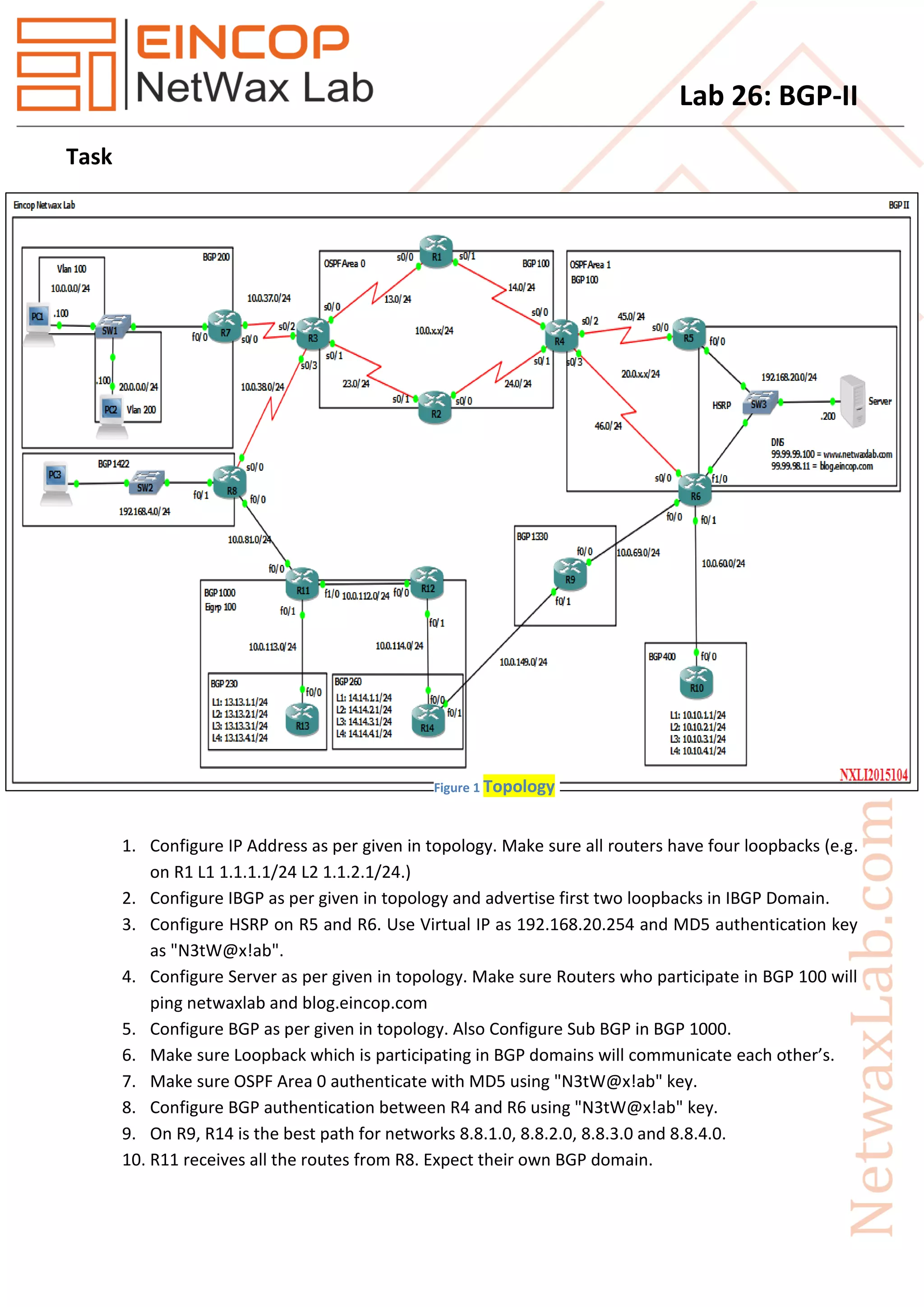
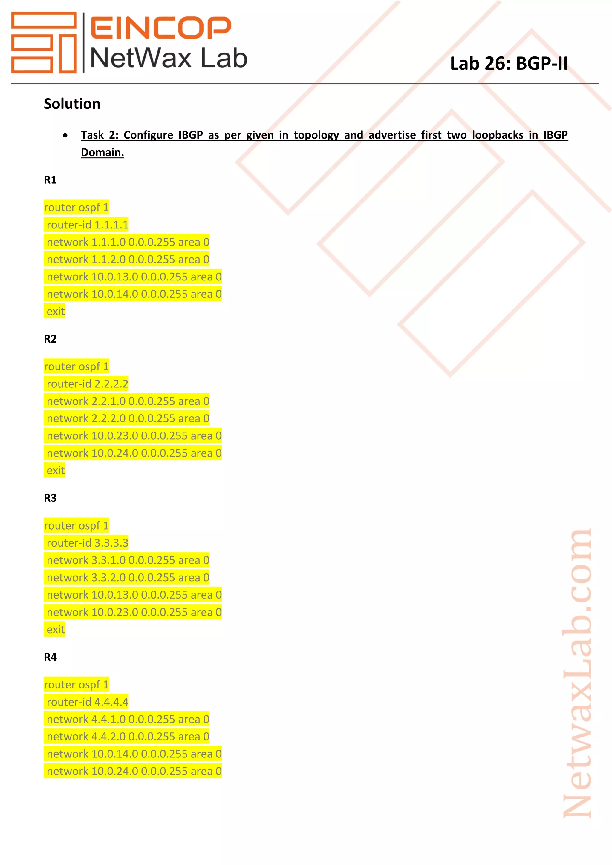
1. The document describes the configuration steps for a lab exercise involving BGP routing. It includes tasks to configure IP addresses, IBGP, HSRP, servers, and BGP routing on multiple routers as shown in the given topology diagram.
2. Key steps are to configure IBGP between routers R1-R4, HSRP between R5-R6, servers on R6, and BGP routing between all routers as specified in the tasks and topology, including IBGP, EBGP, route reflectors, and BGP confederations.
3. The goal is to verify connectivity between loopbacks and servers across the different BGP and IBGP domains as configured.
VRRP (Virtual Router Redundancy Protocol) is a computer networking protocol that provides for
automatic assignment of available Internet Protocol (IP) routers to participating hosts. This increases the
availability and reliability of routing paths via automatic default gateway selections on an IP subnetwork.
The Virtual Router Redundancy Protocol (VRRP) eliminates the single point of failure inherent in the
static default routed environment. VRRP specifies an election protocol that dynamically assigns
responsibility for a virtual router (a VPN 3000 Series Concentrator cluster) to one of the VPN
Concentrators on a LAN. The VRRP VPN Concentrator that controls the IP address(es) associated with a
virtual router is called the Master, and forwards packets sent to those IP addresses.
A
PROJECT REPORT
On
CISCO CERTIFIED NETWORK ASSOCIATE
A computer network, or simply a network, is a collection of computer and other hardware components interconnected by communication channels that allow sharing of resources and information. Where at least one process in one device is able to send/receive data to/from at least one process residing in a remote device, then the two devices are said to be in a network. Simply, more than one computer interconnected through a communication medium for information interchange is called a computer network.
Tunneling provides a mechanism to transport packets of one protocol within another protocol. The
protocol that is carried is called as the passenger protocol, and the protocol that is used for carrying the
passenger protocol is called as the transport protocol. Generic Routing Encapsulation (GRE) is one of the
available tunneling mechanisms which uses IP as the transport protocol and can be used for carrying
many different passenger protocols. The tunnels behave as virtual point-to-point links that have two
endpoints identified by the tunnel source and tunnel destination addresses at each endpoint.
Remote-access VPNs allow secure access to corporate resources by establishing an encrypted tunnel
across the Internet. The ubiquity of the Internet, combined with today's VPN technologies, allows
organizations to cost-effectively and securely extend the reach of their networks to anyone, anyplace,
anytime.
In Computer Networking, the term port can refer to either physical or virtual connection points. In
computer terms, a port generally refers to the female part of connection. Computer ports have many
uses, to connect a monitor, webcam, speakers, or other peripheral devices.
Switching – A Process of using the MAC address on LAN is called Layer 2 Switching.
Layer 2 Switching is the process of using hardware address of devices on a LAN to segment a network.
Switching breaks up large collision domains into smaller ones and that a collision domain is a network
segment with two or more devices sharing the same bandwidth.
Switches direct and control much of the data flowing across computer networks.
Conventional network security often focuses more on routers and blocking traffic from the outside.
Switches are internal to the organization and designed to allow ease of connectivity, therefore only
limited or no security measures are applied.
A network consists of a collection of computers, printers and other compatible equipment/ hardware
that is connected together so that they can communicate with each other.
IP Address is a unique identification given to Host, network device, server for data communication. IP
Address stand for Internet Protocol address, it is an addressing scheme used to identify a system on a
network. It is a unique address that certain electronic devices currently use to communicate with each
other on a network using internet protocol.
For enterprise network engineers, implementing BGP can be an intimidating task. This presentation was given to address common architectures for internet and MPLS BGP usage, along with best practices.
Kerberos is a computer network authentication protocol which works on the basis of 'tickets' to allow
nodes communicating over a non-secure network to prove their identity to one another in a secure
manner. Its designers aimed it primarily at a client–server model and it provides mutual
authentication—both the user and the server verify each other's identity. Kerberos protocol messages
are protected against eavesdropping and replay attacks.
Terminal Access Controller Access-Control System (TACACS, usually pronounced like tack-axe) refers to a
family of related protocols handling remote authentication and related services for networked access
control through a centralized server. The original TACACS protocol, which dates back to 1984, was used
for communicating with an authentication server, common in older UNIX networks;
RADIUS is a protocol for carrying information related to authentication, authorization, and configuration
between a Network Access Server that desires to authenticate its links and a shared Authentication
Server.
RADIUS stands for Remote Authentication Dial In User Service.
RADIUS is an AAA protocol for applications such as Network Access or IP Mobility
It works in both situations, Local and Mobile.
It uses Password Authentication Protocol (PAP), Challenge Handshake Authentication Protocol
(CHAP), or Extensible Authentication Protocol (EAP) protocols to authenticate users.
It look in text file, LDAP Servers, Database for authentication.
1. Lab 26: BGP-II
Task
1. Configure IP Address as per given in topology. Make sure all routers have four loopbacks (e.g.
on R1 L1 1.1.1.1/24 L2 1.1.2.1/24.)
2. Configure IBGP as per given in topology and advertise first two loopbacks in IBGP Domain.
3. Configure HSRP on R5 and R6. Use Virtual IP as 192.168.20.254 and MD5 authentication key
as "N3tW@x!ab".
4. Configure Server as per given in topology. Make sure Routers who participate in BGP 100 will
ping netwaxlab and blog.eincop.com
5. Configure BGP as per given in topology. Also Configure Sub BGP in BGP 1000.
6. Make sure Loopback which is participating in BGP domains will communicate each other’s.
7. Make sure OSPF Area 0 authenticate with MD5 using "N3tW@x!ab" key.
8. Configure BGP authentication between R4 and R6 using "N3tW@x!ab" key.
9. On R9, R14 is the best path for networks 8.8.1.0, 8.8.2.0, 8.8.3.0 and 8.8.4.0.
10. R11 receives all the routes from R8. Expect their own BGP domain.
Figure 1 Topology
2. Lab 26: BGP-II
Solution
Task 2: Configure IBGP as per given in topology and advertise first two loopbacks in IBGP
Domain.
R1
router ospf 1
router-id 1.1.1.1
network 1.1.1.0 0.0.0.255 area 0
network 1.1.2.0 0.0.0.255 area 0
network 10.0.13.0 0.0.0.255 area 0
network 10.0.14.0 0.0.0.255 area 0
exit
R2
router ospf 1
router-id 2.2.2.2
network 2.2.1.0 0.0.0.255 area 0
network 2.2.2.0 0.0.0.255 area 0
network 10.0.23.0 0.0.0.255 area 0
network 10.0.24.0 0.0.0.255 area 0
exit
R3
router ospf 1
router-id 3.3.3.3
network 3.3.1.0 0.0.0.255 area 0
network 3.3.2.0 0.0.0.255 area 0
network 10.0.13.0 0.0.0.255 area 0
network 10.0.23.0 0.0.0.255 area 0
exit
R4
router ospf 1
router-id 4.4.4.4
network 4.4.1.0 0.0.0.255 area 0
network 4.4.2.0 0.0.0.255 area 0
network 10.0.14.0 0.0.0.255 area 0
network 10.0.24.0 0.0.0.255 area 0
3. Lab 26: BGP-II
network 20.0.45.0 0.0.0.255 area 1
network 20.0.46.0 0.0.0.255 area 1
exit
R5
router ospf 1
router-id 5.5.5.5
network 5.5.1.0 0.0.0.255 area 1
network 5.5.2.0 0.0.0.255 area 1
network 20.0.45.0 0.0.0.255 area 1
network 192.168.20.0 0.0.0.255 area 1
exit
R6
router ospf 1
router-id 6.6.6.6
network 6.6.1.0 0.0.0.255 area 1
network 6.6.2.0 0.0.0.255 area 1
network 20.0.46.0 0.0.0.255 area 1
network 192.168.20.0 0.0.0.255 area 1
exit
R11
router eigrp 100
network 10.0.112.0 0.0.0.255
network 10.0.113.0 0.0.0.255
network 11.11.1.0 0.0.0.255
network 11.11.2.0 0.0.0.255
no auto-summary
R12
router eigrp 100
network 10.0.112.0 0.0.0.255
network 10.0.114.0 0.0.0.255
network 12.12.1.0 0.0.0.255
network 12.12.2.0 0.0.0.255
no auto-summary
4. Lab 26: BGP-II
R13
router eigrp 100
network 10.0.113.0 0.0.0.255
network 13.13.1.0 0.0.0.255
network 13.13.2.0 0.0.0.255
no auto-summary
R14
router eigrp 100
network 10.0.114.0 0.0.0.255
network 14.14.1.0 0.0.0.255
network 14.14.2.0 0.0.0.255
no auto-summary
Task 3: Configure HSRP on R5 and R6. Use Virtual IP as 192.168.20.254 and MD5 authentication
key as "N3tW@x!ab".
R5
int f0/0
standby 1 ip 192.168.20.254
standby 1 priority 101
standby 1 preempt
standby 1 authentication md5 key-string N3tW@x!ab
exit
R6
int f1/0
standby 1 ip 192.168.20.254
standby 1 priority 99
standby 1 preempt
standby 1 authentication md5 key-string N3tW@x!ab
exit
5. Lab 26: BGP-II
Task 4: Configure Server as per given in topology. Make sure Routers who participate in BGP
100 will ping netwaxlab and blog.eincop.com
R6
int l1
ip add 99.99.99.100 255.255.255.0
int l2
ip add 99.99.98.11 255.255.255.0
R4, R5 and R6
ip domain lookup
ip name-server 192.168.20.200
Task 5: Configure BGP as per given in topology. Also Configure Sub BGP in BGP 1000. (Task 6
will also complete in this task).
R1
router bgp 100
no synchronization
bgp log-neighbor-changes
network 1.1.3.0 mask 255.255.255.0
network 1.1.4.0 mask 255.255.255.0
neighbor 10.0.13.3 remote-as 100
neighbor 10.0.14.4 remote-as 100
neighbor 10.0.14.4 route-reflector-client
neighbor 10.0.14.4 next-hop-self
no auto-summary
R2
router bgp 100
no synchronization
bgp log-neighbor-changes
network 2.2.3.0 mask 255.255.255.0
network 2.2.4.0 mask 255.255.255.0
neighbor 10.0.23.3 remote-as 100
neighbor 10.0.24.4 remote-as 100
neighbor 10.0.24.4 route-reflector-client
neighbor 10.0.24.4 next-hop-self
no auto-summary
11. Lab 26: BGP-II
no auto-summary
Task 6: Already completed in above task.
Task 7: Make sure OSPF Area 0 authenticate with MD5 using "N3tW@x!ab" key.
R1
router ospf 1
area 0 authentication
exit
int se0/0
ip ospf authentication message-digest
ip ospf message-digest-key 10 md5 N3tW@x!ab
exit
int se0/1
ip ospf authentication message-digest
ip ospf message-digest-key 10 md5 N3tW@x!ab
exit
R2
router ospf 1
area 0 authentication
exit
int se0/0
ip ospf authentication message-digest
ip ospf message-digest-key 10 md5 N3tW@x!ab
exit
int se0/1
ip ospf authentication message-digest
ip ospf message-digest-key 10 md5 N3tW@x!ab
exit
R3
router ospf 1
area 0 authentication
exit
12. Lab 26: BGP-II
int se0/0
ip ospf authentication message-digest
ip ospf message-digest-key 10 md5 N3tW@x!ab
exit
int se0/1
ip ospf authentication message-digest
ip ospf message-digest-key 10 md5 N3tW@x!ab
exit
R4
router ospf 1
area 0 authentication
exit
int se0/0
ip ospf authentication message-digest
ip ospf message-digest-key 10 md5 N3tW@x!ab
exit
int se0/1
ip ospf authentication message-digest
ip ospf message-digest-key 10 md5 N3tW@x!ab
exit
Task 8: Configure BGP authentication between R4 and R6 using "N3tW@x!ab" key.
R4
router bgp 100
neighbor 20.0.46.6 password N3tW@x!ab
exit
R6
router bgp 100
neighbor 20.0.46.4 password N3tW@x!ab
exit
13. Lab 26: BGP-II
Task 9: On R9, R14 is the best path for networks 8.8.1.0, 8.8.2.0, 8.8.3.0 and 8.8.4.0.
R9
access-list 10 permit 8.8.1.0 0.0.0.255
access-list 10 permit 8.8.2.0 0.0.0.255
access-list 10 permit 8.8.3.0 0.0.0.255
access-list 10 permit 8.8.4.0 0.0.0.255
route-map R8 permit 10
match ip address 10
set local-preference 500
exit
route-map R8 permit 20
exit
router bgp 1330
neighbor 10.0.149.14 route-map R8 in
exit
Task 10: R11 receives all the routes from R8. Expect their own BGP domain.
R11
access-list 10 permit 9.9.1.0 0.0.0.255
access-list 10 permit 9.9.2.0 0.0.0.255
access-list 10 permit 9.9.3.0 0.0.0.255
access-list 10 permit 9.9.4.0 0.0.0.255
route-map R9 permit 10
match ip address 10
set weight 1500
exit
route-map R9 permit 20
exit
router bgp 1000
neighbor 10.0.81.8 route-map R9 in
exit