Downloaded 485 times


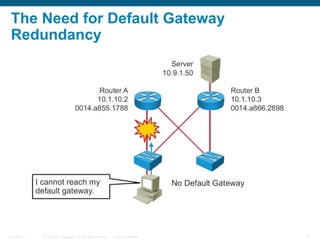
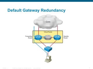
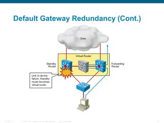
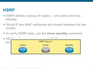
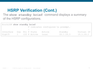
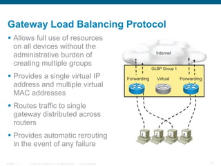
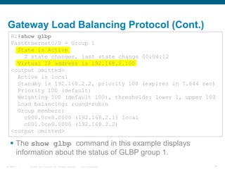
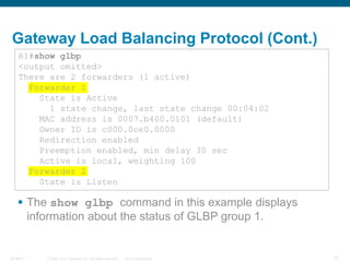
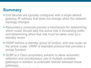

This document discusses layer 3 redundancy protocols. It describes routing issues with redundancy and protocols like HSRP, VRRP, and GLBP that provide a redundant default gateway. HSRP defines an active-standby router group that uses a virtual IP address. GLBP provides load balancing across multiple routers and gateway redundancy through automatic failover.


![Getting Started with Apache Spark: Big Data Made Simple [Free Meetup]](https://cdn.slidesharecdn.com/ss_thumbnails/apachesparkgettingstarted-260203175547-8361bcc3-thumbnail.jpg?width=640&height=640&fit=bounds)


