Nxll21 ospf filtering & summarization
•
1 like•562 views

1. The document provides instructions for configuring OSPF routing, filtering LSAs, and summarizing routes between OSPF areas on a network with multiple routers. 2. Tasks include configuring OSPF on each router, filtering routes between areas, redistributing EIGRP routes into OSPF, and using prefix lists and route summarization. 3. The solution shows the OSPF and redistribution configurations needed on each router to implement the requested tasks and filters.

Recommended
More Related Content
What's hot
What's hot (20)
Viewers also liked
Similar to Nxll21 ospf filtering & summarization
Similar to Nxll21 ospf filtering & summarization (20)
Nxll21 ospf filtering & summarization
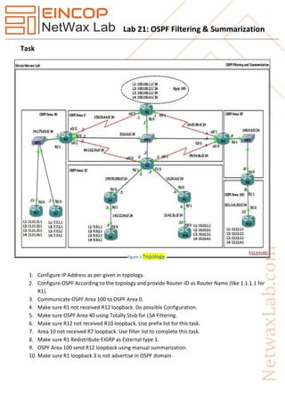
- 1. Lab 21: OSPF Filtering & Summarization Task 1. Configure IP Address as per given in topology. 2. Configure OSPF According to the topology and provide Router-ID as Router Name (like 1.1.1.1 for R1). 3. Communicate OSPF Area 100 to OSPF Area 0. 4. Make sure R1 not received R12 loopback. Do possible Configuration. 5. Make sure OSPF Area 40 using Totally Stub for LSA Filtering. 6. Make sure R12 not received R10 loopback. Use prefix list for this task. 7. Area 10 not received R7 loopback. Use filter list to complete this task. 8. Make sure R1 Redistribute EIGRP as External type 1. 9. OSPF Area 100 send R12 loopback using manual summarization. 10. Make sure R1 loopback 3 is not advertise in OSPF domain. Figure 1 Topology
- 2. Lab 21: OSPF Filtering & Summarization Solution Task 2: Configure OSPF According to the topology and provide Router-ID as Router Name (like 1.1.1.1 for R1). R1 router ospf 1 router-id 1.1.1.1 network 24.45.99.0 0.0.0.255 area 0 network 25.0.0.0 0.0.0.255 area 0 network 158.52.64.0 0.0.0.255 area 0 R2 router ospf 1 router-id 2.2.2.2 network 15.24.0.0 0.0.0.255 area 10 network 25.0.0.0 0.0.0.255 area 0 network 84.122.34.0 0.0.0.255 area 0 network 99.54.66.0 0.0.0.255 area 0 network 199.50.200.0 0.0.0.255 area 10 R3 router ospf 1 network 25.0.0.0 0.0.0.255 area 0 network 74.175.65.0 0.0.0.255 area 40 network 84.122.34.0 0.0.0.255 area 0 network 158.52.64.0 0.0.0.255 area 0 R4 router ospf 1 router-id 4.4.4.4 network 24.45.99.0 0.0.0.255 area 0 network 25.0.0.0 0.0.0.255 area 0 network 99.54.66.0 0.0.0.255 area 0 network 100.0.0.0 0.0.0.255 area 87
- 3. Lab 21: OSPF Filtering & Summarization R5 router ospf 1 router-id 5.5.5.5 network 145.33.54.0 0.0.0.255 area 10 network 199.50.200.0 0.0.0.255 area 10 R6 router ospf 1 router-id 6.6.6.6 network 15.24.0.0 0.0.0.255 area 10 network 33.42.21.0 0.0.0.255 area 10 R7 router ospf 1 router-id 7.7.7.7 network 7.7.1.1 0.0.0.0 area 40 network 7.7.2.1 0.0.0.0 area 40 network 7.7.3.1 0.0.0.0 area 40 network 7.7.4.1 0.0.0.0 area 40 network 74.175.65.0 0.0.0.255 area 40 R8 router ospf 1 router-id 8.8.8.8 area 100 range 12.12.0.0 255.255.248.0 network 100.0.0.0 0.0.0.255 area 87 network 201.114.25.0 0.0.0.255 area 100 R9 router ospf 1 router-id 9.9.9.9 network 9.9.1.1 0.0.0.0 area 10 network 9.9.2.1 0.0.0.0 area 10 network 9.9.3.1 0.0.0.0 area 10 network 9.9.4.1 0.0.0.0 area 10 network 145.33.54.0 0.0.0.255 area 10
- 4. Lab 21: OSPF Filtering & Summarization R10 router ospf 1 router-id 10.10.10.10 network 10.10.1.0 0.0.0.255 area 10 network 10.10.2.0 0.0.0.255 area 10 network 10.10.3.0 0.0.0.255 area 10 network 10.10.4.0 0.0.0.255 area 10 network 33.42.21.0 0.0.0.255 area 10 R11 router ospf 1 router-id 11.11.11.11 network 11.11.11.1 0.0.0.0 area 40 network 11.11.12.1 0.0.0.0 area 40 network 11.11.13.1 0.0.0.0 area 40 network 11.11.14.1 0.0.0.0 area 40 network 74.175.65.0 0.0.0.255 area 40 R12 router ospf 1 router-id 12.12.12.12 network 12.12.1.1 0.0.0.0 area 100 network 12.12.2.1 0.0.0.0 area 100 network 12.12.3.1 0.0.0.0 area 100 network 12.12.4.1 0.0.0.0 area 100 network 201.114.25.0 0.0.0.255 area 100 Task 3: Communicate OSPF Area 100 to OSPF Area 0. R4 router ospf 1 area 87 virtual-link 8.8.8.8 R8 router ospf 1 area 87 virtual-link 4.4.4.4
- 5. Lab 21: OSPF Filtering & Summarization Task 4: Make sure R1 not received R12 loopback. Do possible Configuration. R1 access-list 10 deny 12.12.1.0 0.0.0.255 access-list 10 deny 12.12.2.0 0.0.0.255 access-list 10 deny 12.12.3.0 0.0.0.255 access-list 10 deny 12.12.4.0 0.0.0.255 access-list 10 permit any router ospf 1 distribute-list 10 in FastEthernet0/0 exit Task 5: Make sure OSPF Area 40 using Totally Stub for LSA Filtering. R3 router ospf 1 area 40 stub no-summary exit R7 router ospf 1 area 40 stub exit R11 router ospf 1 area 40 stub exit Task 6: Make sure R12 not received R10 loopback. Use prefix list for this task. R12 ip prefix-list R10loop seq 5 deny 10.10.0.0/16 ge 24 le 24 ip prefix-list R10loop seq 10 permit 0.0.0.0/0 le 32 router ospf 1 distribute-list prefix R10loop in FastEthernet0/0 exit
- 6. Lab 21: OSPF Filtering & Summarization Task 7: Area 10 not received R7 loopback. Use filter list to complete this task. R2 ip prefix-list R7loop seq 5 deny 7.7.0.0/16 ge 24 le 24 ip prefix-list R7loop seq 10 permit 0.0.0.0/0 le 32 router ospf 1 area 10 filter-list prefix R7loop in exit Task 8: Make sure R1 Redistribute Eigrp as External type 1. R1 router ospf 1 redistribute eigrp 100 metric 1 metric-type 1 subnets exit Task 9: OSPF Area 100 send R12 loopback using manual summarization. R8 router ospf 1 area 100 range 12.12.0.0 255.255.248.0 exit Task 10: Make sure R1 loopback 3 is not advertise in ospf domain. R1 router ospf 1 summary-address 100.100.3.0 255.255.255.0 not-advertise exit