Downloaded 152 times

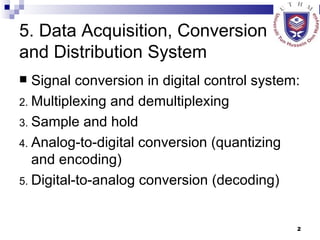
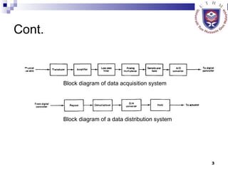
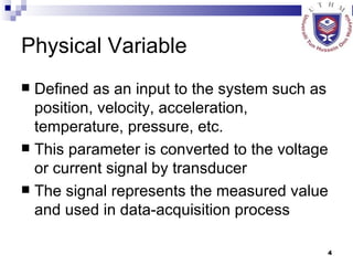
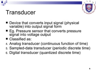
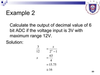
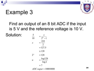
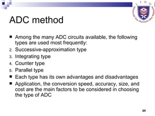
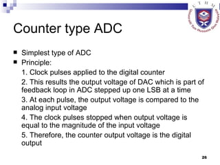
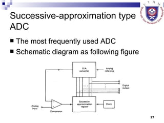

The document discusses data acquisition, conversion, and distribution systems in digital control systems. It describes how physical variables are converted to electrical signals via transducers, then amplified and filtered before being multiplexed and converted to digital signals using analog-to-digital converters (ADCs). It provides examples of calculating quantization levels and ADC outputs. Counter-type and successive-approximation ADCs are discussed as common conversion methods.