Downloaded 737 times


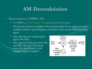


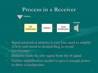


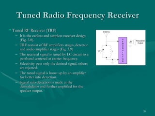


1) This document discusses different types of AM receivers including their components and characteristics. It covers AM demodulators such as envelope detectors and product detectors used to extract the audio signal from the AM carrier wave. 2) Key receiver parameters that determine performance are discussed such as selectivity, sensitivity, bandwidth improvement factor, dynamic range, fidelity and insertion loss. Selectivity refers to a receiver's ability to reject unwanted signals, while sensitivity is the minimum signal it can detect. 3) Bandwidth improvement factor reduces noise by decreasing the ratio of RF bandwidth to IF bandwidth. Dynamic range is the range between minimum and maximum usable input signals before distortion occurs.