Downloaded 101 times


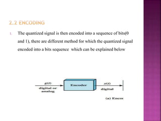


This document discusses analog to digital conversion techniques. It explains that analog signals are continuous while digital signals are discrete. It also describes three main techniques in A/D conversion: sampling, quantization, and encoding. Sampling converts a continuous signal to discrete samples. Quantization maps samples to a smaller set of values, introducing quantization error. Encoding converts quantized values into a binary format.