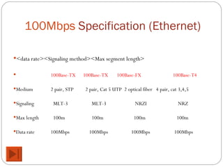
High Speed  LAN s Data and Computer Communications
Introduction IEEE 802.3 standard (Ethernet) cover data rates of: 10 Mbps(Ethernet), 100 Mbps(Fast Ethernet)     CSMA/CD MAC protocol  1Gbps and 10 Gbps (Gigabit Ethernet)    switched technique Range of technologies Fast and Gigabit Ethernet Extention of 10 Mbps CSMA/CD to higher speeds Fibre  Channel    switched technique Provides a low-cost, easy approach to achieve very high data rates High Speed Wireless LANs (CSMA/CD : carrier sense multiple access with collision detection)
Why High Speed LANs? Office  LANs  used to  provide basic connectivity Connecting PCs  and terminals to mainframes and midrange systems that ran corporate applications Providing  workgroup connectivity at departmental level Emphasis  on file transfer and electronic mail Speed  and power of  PCs  has  risen Graphics -intensive applications  and GUIs MIS   ( Management information Systems )  organizations recognize LAN s  as essential  Began  with client/server computing Now  dominant architecture in business environment Intranetworks Frequent  transfer of large volumes of data  'MIS' is a planned system of collecting, storing and disseminating data in the form of information needed to carry out the functions of management.
Applications Requiring High Speed LANs Centralized server farms User needs to  draw  huge amounts of data  from multiple centralized servers (servers farms) E.g. Color  publishing Servers  contain tens of gigabytes of image data Downloaded  to imaging workstations Power workgroups Small  number of cooperating users Draw   massive data files across network E.g. Software  development group  testing  new software version  or  computer-aided design (CAD)  running  simulations High-speed local backbone Processing  demand grows LANs   grow at site High -speed interconnection is necessary
 
IEEE802.3 Medium Access Control CDMA/CD and its ancestor can be termed   random access, or contention,  techniques. Random Access Stations access medium randomly Contention  (fight) Stations content for time on medium Scheme from which CSMA/CD evolved ALOHA / pure ALOHA Slotted ALOHA CSMA      algorithm used: nonpersistent CSMA,    1-persistent protocol,  p- persistent
ALOHA  /  pure ALOHA Developed for packet radio network  a station can transmit a frame at any time When station has frame, it sends Station listens (for max round trip time)plus small increment If ACK, fine.  If not, retransmit If no ACK after repeated transmissions, give up Receiving station: Frame check sequence (as in HDLC) If frame OK and address matches receiver, send ACK Frame may be damaged by noise or by another station transmitting at the same time (collision) Any overlap of frames causes collision If frame received is determined to be invalid, receiving station ignores it Max utilization 18% (collision rises rapidly with increased load)
Slotted ALOHA To prove efficiency,  time  on the channel  is organized  in to  uniform slots equal to frame transmission time Need central clock (or other sync mechanism) Transmission permitted only to begin at slot boundary Frames either miss or overlap totally Max utilization 37%
Pure ALOHA vs Slotted ALOHA In pure Aloha, a  user can transmit at any time but risks  collisions  with other users' messages.   "Slotted Aloha" reduces the chance of collisions by  dividing the channel into time slots and requiring that the user send only at the beginning of a time slot.
CSMA   (carrier sense multiple access) A station wishing to transmit first listens to the medium to determine if another transmission is in progress  (carrier sense) All stations know that a transmission has started almost immediately First listen for clear medium (carrier sense) If medium idle, transmit If two stations start at the same instant, collision Wait reasonable time (round trip  plus ACK contention) No ACK then retransmit No ACK = collision
CSMA   (carrier sense multiple access) Max utilization depends on propagation time (medium length) and frame length Longer frame and shorter propagation gives better utilization Better than ALOHA and slotted ALOHA With CSMA, an algorithm is needed to specify what a station should do if the medium is found busy. nonpersistent CSMA, 1-persistent protocol p- persistent
Nonpersistent CSMA -  attempts to reduce collision If medium is idle, transmit; otherwise,  go to 2 If medium is busy, wait amount of time drawn from probability distribution (retransmission delay) and repeat 1   Random  delays reduces probability of collisions Consider  two stations become ready to transmit at same time  While  another transmission is in progress If  both stations delay same time before  retrying,  both  will  attempt to transmit at same time Capacity  is wasted because medium will remain idle following end of transmission Even  if one or more stations waiting Nonpersistent  stations deferential
1-persistent CSMA -attempts to reduce idle time To avoid idle channel time, 1-persistent protocol used Station  wishing to transmit listens and obeys following :   If medium idle, transmit; otherwise, go to step 2 If medium busy, listen until idle; then transmit immediately 1-persistent stations selfish   If two or more stations waiting ,  collision guaranteed Gets  sorted out after collision
P-persistent CSMA Compromise  that attempts to reduce collisions Like  nonpersistent And  reduce idle time Like 1-persistent Rules : If  medium idle, transmit with probability p, and delay one time unit with probability (1 – p) Time  unit typically maximum propagation delay If medium busy, listen until idle and repeat step 1 If transmission is delayed one time unit, repeat step 1
CSMA/CD With CSMA, collision occupies medium for duration of transmission Medium unusable   waste CSMA/CD : To reduce waste, stations listen whilst transmitting If medium idle, transmit , otherwise, step 2 If busy, listen for idle, then transmit If collision detected,  transmit a jamming signal  then cease transmission   (backoff) After jam, wait random time then start  from step 1 IEEE 802.3  uses  1-persistent IEEE 802.3  uses  1-persistent  algorithm
CSMA/CD Operation
IEEE 802.3 Frame Format
10Mbps  Specification (Ethernet) In Ethernet, IEEE defines types of cable, connections, and signals used( physical  layer  standards) <data rate><Signaling method><Max segment length> 10Base5 10Base2 10Base-T 10Base-F Medium Coaxial Coaxial UTP 850nm fiber Signaling Baseband Baseband Baseband Manchester Manchester Manchester Manchester On/Off Max length 500m 185m 100m 500m Topology Bus Bus Star Star Nodes 100 30 - 33
100Mbps Fast Ethernet Use  IEEE 802.3 MAC protocol and frame format 100BASE-X use physical medium specifications  from  FDDI Two  physical links between nodes Transmission  and reception Star -wire topology Similar  to 10BASE-T
10 0 Mbps  Specification (Ethernet) In Ethernet, IEEE defines types of cable, connections, and signals used( physical  layer  standards) <data rate><Signaling method><Max segment length> 100Base-TX  100Base-TX  100Base-FX    100Base-T4 Medium 2 pair, STP  2 pair, Cat 5   UTP  2 optical fiber  4 pair, cat 3,4,5 Signaling   MLT-3    MLT-3    NRZI    NRZ Max length   100m   100m    100m    100m   Data rate 100Mbps   100Mbps     100Mbps     100Mbps
100BASE-T Options
Full Duplex Operation Traditional  Ethernet half duplex Either  transmit or receive but not both simultaneously With full-duplex ,  station can transmit and receive simultaneously 100-Mbps Ethernet in full-duplex mode, theoretical transfer rate 200 Mbps Attached  stations must have  full-duplex adapter cards   (traditional Ethernet: half-duplex adapter cards) Must use   switching hub (traditional Ethernet: multiport repeater /hub) Each  station constitutes separate collision domain In fact, no collisions CSMA/CD algorithm no longer needed 802.3 MAC frame format used Attached  stations can continue CSMA/CD
Mixed Configurations Fast Ethernet supports mixture of existing 10-Mbps   LANs and newer 100-Mbps LANs E.g.  100-Mbps backbone LAN to support 10-Mbps hubs Stations  attach to 10-Mbps hubs using 10BASE-T  Hubs  connected to switching hubs  using  100BASE-T Support  10-Mbps and 100-Mbps High -capacity workstations and servers attach directly to 10/100 switches Switches  connected to 100-Mbps hubs using 100-Mbps links 100-Mbps hubs provide building backbone Connected  to   router  providing  connection to WAN
Gigabit Ethernet Configuration
Gigabit Ethernet – Physical In Ethernet, IEEE defines types of cable, connections, and signals used( physical standards) 1000Base-SX Short wavelength, multimode fiber 1000Base-LX Long wavelength, Multi or single mode fiber 1000Base-CX Copper jumpers <25m, shielded twisted pair 1000Base-T 4 pairs, cat 5 UTP Signaling  (encoding scheme)  - 8B/10B
Gbit Ethernet Medium Options (log scale)
10Gbps Ethernet - Uses High -speed, local backbone interconnection between large-capacity switches Server  farm Campus  wide connectivity Enables  Internet service providers (ISPs) and network service providers (NSPs) to create very high-speed links at very low cost Allows  construction of (MANs) and WANs Connect  geographically dispersed LANs between campuses or points of presence (PoPs) Ethernet compete s  with ATM and other  WAN  technologies 10-Gbps Ethernet provides considerable   value over ATM
10Gbps Ethernet -  Physical Maximum  link distances cover 300 m to 40 km Full -duplex mode only 10GBASE-S (short): 850 nm on multimode fiber Up  to 300 m 10GBASE-L (long) 1310 nm on single-mode fiber Up  to 10 km 10GBASE-E (extended) 1550 nm on single-mode fiber Up  to 40 km 10GBASE-LX4: 1310 nm on single-mode or multimode fiber Up  to 10 km Wavelength -division multiplexing (WDM) bit stream across four light waves
10Gbps Ethernet Distance Options (log  scale)
Token Ring  (802.5) Developed from  IBM's commercial token ring Because of IBM's presence, token ring  has  gained broad acceptance Never  achieved popularity of Ethernet Currently, large installed base of token ring products
Ring  Operation Each repeater connects to two others via unidirectional transmission links Single closed path Data transferred bit by bit from one repeater to the next Repeater regenerates and retransmits each bit Repeater performs data insertion, data reception, data removal Repeater acts as attachment point Packet removed by transmitter after one trip round ring
802.5  MAC Protocol Small frame (token) circulates when idle Station waits for token Changes one bit in token to make it SOF  (start of frame)  for data frame A ttach   rest of data frame Frame makes round trip and is absorbed by transmitting station Station then inserts new token when transmission has finished and leading edge of returning frame arrives Under light loads, some inefficiency Under heavy loads, round robin
Token Ring Operation
Fibre Channel - Background Data comms with processor: I/O channel Direct point to point or multipoint comms link Hardware based High Speed Very short distance User data moved from source buffer to destination buffer Network connection Interconnected access points Software based protocol Flow control, error detection &recovery End systems connections
Fibre Channel Best of both technologies Channel oriented Simplicity and speed Network oriented Flexibility and interconnectivity
Fibre Channel Requirements Full duplex links with two fibers per link 100 Mbps to 800 Mbps on single line  Full  duplex 200 Mbps to 1600 Mbps per link Up  to 10 km Supports  simple encoding and framing scheme In  turn supports a variety of channel and network protocols
Fibre Channel Elements End systems - Nodes Switched elements - the network or fabric Communication across point to point links
Fibre Channel Network
Fibre Channel Protocol Architecture (1) Fibre Channel standard is organized into five levels: FC-0 Physical Media Optical fiber for long distance coaxial cable for high speed short distance STP for lower speed short distance FC-1 Transmission Protocol 8B/10B signal encoding FC-2 Framing Protocol Topologies Framing formats Flow and error control Sequences and exchanges (logical grouping of frames)  FC- 3  Common Services Including multicasting FC-4 Mapping Mapping of channel and network services onto fibre channel e.g. IEEE 802, ATM, IP, SCSI
Fibre Channel Physical Media Provides  range of options for physical medium, the data rate on medium, and topology of network Shielded  twisted pair, video coaxial cable, and optical fiber Data  rates 100 Mbps to 3.2 Gbps Point-to-point from 33 m to 10 km
Fabric Advantages Scalability  of capacity As  additional ports added, aggregate capacity of network increases Minimizes  congestion and contention Increases  throughput Protocol  independent Distance  insensitive Switch  and transmission link  technologies  may change without affecting overall configuration Burden  on nodes minimized Fibre  Channel node responsible for managing point-to-point connection between itself and fabric Fabric  responsible for routing and error detection
Alternative Topologies Point -to-point topology Only  two ports Directly  connected, with no intervening switches No  routing Arbitrated  loop topology Simple , low-cost topology Up  to 126 nodes in loop Operates  roughly equivalent to token ring Topologies, transmission media, and data rates may be combined
Five Applications of Fibre Channel END!!

10 high speedla-ns

  • 1.
    High Speed LAN s Data and Computer Communications
  • 2.
    Introduction IEEE 802.3standard (Ethernet) cover data rates of: 10 Mbps(Ethernet), 100 Mbps(Fast Ethernet)  CSMA/CD MAC protocol 1Gbps and 10 Gbps (Gigabit Ethernet)  switched technique Range of technologies Fast and Gigabit Ethernet Extention of 10 Mbps CSMA/CD to higher speeds Fibre Channel  switched technique Provides a low-cost, easy approach to achieve very high data rates High Speed Wireless LANs (CSMA/CD : carrier sense multiple access with collision detection)
  • 3.
    Why High SpeedLANs? Office LANs used to provide basic connectivity Connecting PCs and terminals to mainframes and midrange systems that ran corporate applications Providing workgroup connectivity at departmental level Emphasis on file transfer and electronic mail Speed and power of PCs has risen Graphics -intensive applications and GUIs MIS ( Management information Systems ) organizations recognize LAN s as essential Began with client/server computing Now dominant architecture in business environment Intranetworks Frequent transfer of large volumes of data  'MIS' is a planned system of collecting, storing and disseminating data in the form of information needed to carry out the functions of management.
  • 4.
    Applications Requiring HighSpeed LANs Centralized server farms User needs to draw huge amounts of data from multiple centralized servers (servers farms) E.g. Color publishing Servers contain tens of gigabytes of image data Downloaded to imaging workstations Power workgroups Small number of cooperating users Draw massive data files across network E.g. Software development group testing new software version or computer-aided design (CAD) running simulations High-speed local backbone Processing demand grows LANs grow at site High -speed interconnection is necessary
  • 5.
  • 6.
    IEEE802.3 Medium AccessControl CDMA/CD and its ancestor can be termed random access, or contention, techniques. Random Access Stations access medium randomly Contention (fight) Stations content for time on medium Scheme from which CSMA/CD evolved ALOHA / pure ALOHA Slotted ALOHA CSMA  algorithm used: nonpersistent CSMA, 1-persistent protocol, p- persistent
  • 7.
    ALOHA / pure ALOHA Developed for packet radio network a station can transmit a frame at any time When station has frame, it sends Station listens (for max round trip time)plus small increment If ACK, fine. If not, retransmit If no ACK after repeated transmissions, give up Receiving station: Frame check sequence (as in HDLC) If frame OK and address matches receiver, send ACK Frame may be damaged by noise or by another station transmitting at the same time (collision) Any overlap of frames causes collision If frame received is determined to be invalid, receiving station ignores it Max utilization 18% (collision rises rapidly with increased load)
  • 8.
    Slotted ALOHA Toprove efficiency, time on the channel is organized in to uniform slots equal to frame transmission time Need central clock (or other sync mechanism) Transmission permitted only to begin at slot boundary Frames either miss or overlap totally Max utilization 37%
  • 9.
    Pure ALOHA vsSlotted ALOHA In pure Aloha, a user can transmit at any time but risks collisions with other users' messages. &quot;Slotted Aloha&quot; reduces the chance of collisions by dividing the channel into time slots and requiring that the user send only at the beginning of a time slot.
  • 10.
    CSMA (carrier sense multiple access) A station wishing to transmit first listens to the medium to determine if another transmission is in progress (carrier sense) All stations know that a transmission has started almost immediately First listen for clear medium (carrier sense) If medium idle, transmit If two stations start at the same instant, collision Wait reasonable time (round trip plus ACK contention) No ACK then retransmit No ACK = collision
  • 11.
    CSMA (carrier sense multiple access) Max utilization depends on propagation time (medium length) and frame length Longer frame and shorter propagation gives better utilization Better than ALOHA and slotted ALOHA With CSMA, an algorithm is needed to specify what a station should do if the medium is found busy. nonpersistent CSMA, 1-persistent protocol p- persistent
  • 12.
    Nonpersistent CSMA - attempts to reduce collision If medium is idle, transmit; otherwise, go to 2 If medium is busy, wait amount of time drawn from probability distribution (retransmission delay) and repeat 1   Random delays reduces probability of collisions Consider two stations become ready to transmit at same time While another transmission is in progress If both stations delay same time before retrying, both will attempt to transmit at same time Capacity is wasted because medium will remain idle following end of transmission Even if one or more stations waiting Nonpersistent stations deferential
  • 13.
    1-persistent CSMA -attemptsto reduce idle time To avoid idle channel time, 1-persistent protocol used Station wishing to transmit listens and obeys following :   If medium idle, transmit; otherwise, go to step 2 If medium busy, listen until idle; then transmit immediately 1-persistent stations selfish If two or more stations waiting , collision guaranteed Gets sorted out after collision
  • 14.
    P-persistent CSMA Compromise that attempts to reduce collisions Like nonpersistent And reduce idle time Like 1-persistent Rules : If medium idle, transmit with probability p, and delay one time unit with probability (1 – p) Time unit typically maximum propagation delay If medium busy, listen until idle and repeat step 1 If transmission is delayed one time unit, repeat step 1
  • 15.
    CSMA/CD With CSMA,collision occupies medium for duration of transmission Medium unusable  waste CSMA/CD : To reduce waste, stations listen whilst transmitting If medium idle, transmit , otherwise, step 2 If busy, listen for idle, then transmit If collision detected, transmit a jamming signal then cease transmission (backoff) After jam, wait random time then start from step 1 IEEE 802.3 uses 1-persistent IEEE 802.3 uses 1-persistent algorithm
  • 16.
  • 17.
  • 18.
    10Mbps Specification(Ethernet) In Ethernet, IEEE defines types of cable, connections, and signals used( physical layer standards) <data rate><Signaling method><Max segment length> 10Base5 10Base2 10Base-T 10Base-F Medium Coaxial Coaxial UTP 850nm fiber Signaling Baseband Baseband Baseband Manchester Manchester Manchester Manchester On/Off Max length 500m 185m 100m 500m Topology Bus Bus Star Star Nodes 100 30 - 33
  • 19.
    100Mbps Fast EthernetUse IEEE 802.3 MAC protocol and frame format 100BASE-X use physical medium specifications from FDDI Two physical links between nodes Transmission and reception Star -wire topology Similar to 10BASE-T
  • 20.
    10 0 Mbps Specification (Ethernet) In Ethernet, IEEE defines types of cable, connections, and signals used( physical layer standards) <data rate><Signaling method><Max segment length> 100Base-TX 100Base-TX 100Base-FX 100Base-T4 Medium 2 pair, STP 2 pair, Cat 5 UTP 2 optical fiber 4 pair, cat 3,4,5 Signaling MLT-3 MLT-3 NRZI NRZ Max length 100m 100m 100m 100m Data rate 100Mbps 100Mbps 100Mbps 100Mbps
  • 21.
  • 22.
    Full Duplex OperationTraditional Ethernet half duplex Either transmit or receive but not both simultaneously With full-duplex , station can transmit and receive simultaneously 100-Mbps Ethernet in full-duplex mode, theoretical transfer rate 200 Mbps Attached stations must have full-duplex adapter cards (traditional Ethernet: half-duplex adapter cards) Must use switching hub (traditional Ethernet: multiport repeater /hub) Each station constitutes separate collision domain In fact, no collisions CSMA/CD algorithm no longer needed 802.3 MAC frame format used Attached stations can continue CSMA/CD
  • 23.
    Mixed Configurations FastEthernet supports mixture of existing 10-Mbps LANs and newer 100-Mbps LANs E.g. 100-Mbps backbone LAN to support 10-Mbps hubs Stations attach to 10-Mbps hubs using 10BASE-T Hubs connected to switching hubs using 100BASE-T Support 10-Mbps and 100-Mbps High -capacity workstations and servers attach directly to 10/100 switches Switches connected to 100-Mbps hubs using 100-Mbps links 100-Mbps hubs provide building backbone Connected to router providing connection to WAN
  • 24.
  • 25.
    Gigabit Ethernet –Physical In Ethernet, IEEE defines types of cable, connections, and signals used( physical standards) 1000Base-SX Short wavelength, multimode fiber 1000Base-LX Long wavelength, Multi or single mode fiber 1000Base-CX Copper jumpers <25m, shielded twisted pair 1000Base-T 4 pairs, cat 5 UTP Signaling (encoding scheme) - 8B/10B
  • 26.
    Gbit Ethernet MediumOptions (log scale)
  • 27.
    10Gbps Ethernet -Uses High -speed, local backbone interconnection between large-capacity switches Server farm Campus wide connectivity Enables Internet service providers (ISPs) and network service providers (NSPs) to create very high-speed links at very low cost Allows construction of (MANs) and WANs Connect geographically dispersed LANs between campuses or points of presence (PoPs) Ethernet compete s with ATM and other WAN technologies 10-Gbps Ethernet provides considerable value over ATM
  • 28.
    10Gbps Ethernet - Physical Maximum link distances cover 300 m to 40 km Full -duplex mode only 10GBASE-S (short): 850 nm on multimode fiber Up to 300 m 10GBASE-L (long) 1310 nm on single-mode fiber Up to 10 km 10GBASE-E (extended) 1550 nm on single-mode fiber Up to 40 km 10GBASE-LX4: 1310 nm on single-mode or multimode fiber Up to 10 km Wavelength -division multiplexing (WDM) bit stream across four light waves
  • 29.
    10Gbps Ethernet DistanceOptions (log scale)
  • 30.
    Token Ring (802.5) Developed from IBM's commercial token ring Because of IBM's presence, token ring has gained broad acceptance Never achieved popularity of Ethernet Currently, large installed base of token ring products
  • 31.
    Ring OperationEach repeater connects to two others via unidirectional transmission links Single closed path Data transferred bit by bit from one repeater to the next Repeater regenerates and retransmits each bit Repeater performs data insertion, data reception, data removal Repeater acts as attachment point Packet removed by transmitter after one trip round ring
  • 32.
    802.5 MACProtocol Small frame (token) circulates when idle Station waits for token Changes one bit in token to make it SOF (start of frame) for data frame A ttach rest of data frame Frame makes round trip and is absorbed by transmitting station Station then inserts new token when transmission has finished and leading edge of returning frame arrives Under light loads, some inefficiency Under heavy loads, round robin
  • 33.
  • 34.
    Fibre Channel -Background Data comms with processor: I/O channel Direct point to point or multipoint comms link Hardware based High Speed Very short distance User data moved from source buffer to destination buffer Network connection Interconnected access points Software based protocol Flow control, error detection &recovery End systems connections
  • 35.
    Fibre Channel Bestof both technologies Channel oriented Simplicity and speed Network oriented Flexibility and interconnectivity
  • 36.
    Fibre Channel RequirementsFull duplex links with two fibers per link 100 Mbps to 800 Mbps on single line Full duplex 200 Mbps to 1600 Mbps per link Up to 10 km Supports simple encoding and framing scheme In turn supports a variety of channel and network protocols
  • 37.
    Fibre Channel ElementsEnd systems - Nodes Switched elements - the network or fabric Communication across point to point links
  • 38.
  • 39.
    Fibre Channel ProtocolArchitecture (1) Fibre Channel standard is organized into five levels: FC-0 Physical Media Optical fiber for long distance coaxial cable for high speed short distance STP for lower speed short distance FC-1 Transmission Protocol 8B/10B signal encoding FC-2 Framing Protocol Topologies Framing formats Flow and error control Sequences and exchanges (logical grouping of frames) FC- 3 Common Services Including multicasting FC-4 Mapping Mapping of channel and network services onto fibre channel e.g. IEEE 802, ATM, IP, SCSI
  • 40.
    Fibre Channel PhysicalMedia Provides range of options for physical medium, the data rate on medium, and topology of network Shielded twisted pair, video coaxial cable, and optical fiber Data rates 100 Mbps to 3.2 Gbps Point-to-point from 33 m to 10 km
  • 41.
    Fabric Advantages Scalability of capacity As additional ports added, aggregate capacity of network increases Minimizes congestion and contention Increases throughput Protocol independent Distance insensitive Switch and transmission link technologies may change without affecting overall configuration Burden on nodes minimized Fibre Channel node responsible for managing point-to-point connection between itself and fabric Fabric responsible for routing and error detection
  • 42.
    Alternative Topologies Point-to-point topology Only two ports Directly connected, with no intervening switches No routing Arbitrated loop topology Simple , low-cost topology Up to 126 nodes in loop Operates roughly equivalent to token ring Topologies, transmission media, and data rates may be combined
  • 43.
    Five Applications ofFibre Channel END!!