Downloaded 554 times
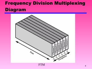
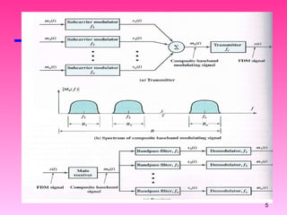
![Frequency Division Multiplexing FDM Possible if useful bandwidth of medium exceeds( melebihi ) required bandwidth of channel [ bandwidth/frequency range : medium>signal ] Each signal is modulated to a different carrier frequency Carrier frequencies separated so signals do not overlap (guard bands) e.g. broadcast radio Channel allocated even if no data](https://image.slidesharecdn.com/7-multiplexing-111203165031-phpapp01/85/7-multiplexing-3-320.jpg)
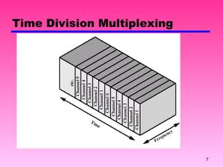
![Synchronous Time Division Multiplexing (TDM) Possible if data rate of medium exceeds data rate of digital signal to be transmitted [ data rate : medium>signal ] Multiple digital signals interleaved in time Interleaving can be at bit level of blocks Time slots pre-assigned to sources and fixed Time slots allocated even if no data to send](https://image.slidesharecdn.com/7-multiplexing-111203165031-phpapp01/85/7-multiplexing-6-320.jpg)
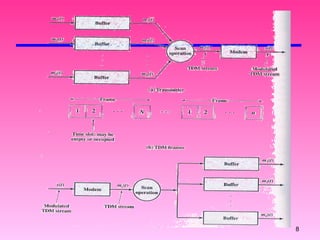
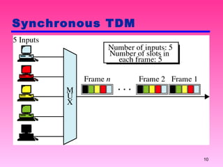
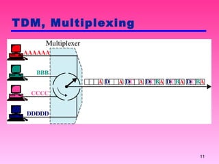
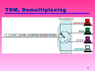
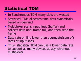
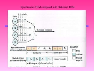
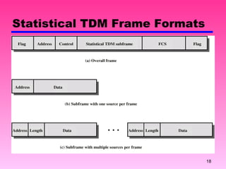
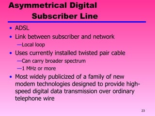

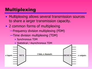
Multiplexing allows multiple transmission sources to share a larger transmission capacity through techniques like frequency division multiplexing (FDM) and time division multiplexing (TDM). FDM allocates different carrier frequencies to different signals so they do not overlap. TDM interleaves multiple digital signals in time by assigning fixed time slots. Statistical TDM dynamically allocates time slots based on demand to make more efficient use of bandwidth compared to synchronous TDM which allocates slots even if they are empty.