SlideShare a Scribd company logo
1 of 28
Download to read offline
Department of Mechanical Engineering
Shri Ramdeobaba college of Engineering and Management, Nagpur
Instrumentation and Control
Semester / Session – VI / 2020-2021
Topic – A to D Convertors
TA 3 - Group – 12
Group Members:
56 – Rishi Agrawal
57 – Ritik Singh
58 – Sagar Chaudhari
59 – Sahil Telani
60 – Sangeet Khule
Course Co-ordinator:
Dr. P.S. Deole
What is A to D convertor
Working of A to D convertor
Types of ADC’s
Successive Approximation ADC
Delta Sigma ADC
Dual Slope ADC
Flash ADC
Pipelined ADC
Applications of ADC’s
Testing
Calibration and Need for Calibration
References
•A data converter which allows digital circuits to interface with the real world by encoding an analogue signal into a binary
code.
•It allows micro-processor controlled circuits, Arduinos, Raspberry Pi, and other such digital logic circuits to communicate
with the real world.
•In the real world, analogue signals have continuously changing values which come from various sources and sensors which
can measure sound, light, temperature or movement, and many digital systems interact with their environment by
measuring the analogue signals from such transducers.
•Digital circuits on the other hand work with binary signal which have only two discrete states, a logic “1” (HIGH) or a logic
“0” (LOW).
•So it is necessary to have an electronic circuit which can convert between the two different domains of continuously
changing analogue signals and discrete digital signals, and this is where Analogue-to-Digital Converters (A/D) come in.
• Basically an analogue to digital converter takes a snapshot of an analogue voltage at one instant in time and
produces a digital output code which represents this analogue voltage.
• The number of binary digits, or bits used to represent this analogue voltage value depends on the resolution
of an A/D converter.
• ADCs follow a sequence when converting analog signals to digital. They first sample the signal, then quantify
it to determine the resolution of the signal, and finally set binary values and send it to the system to read the
digital signal.
• Two important aspects of the ADC are its sampling rate and resolution.
• Microcontrollers can’t read values unless it’s digital data. This is because microcontrollers can only see
“levels” of the voltage, which depends on the resolution of the ADC and the system voltage.
Fig 1: Working of ADC’s
There are basically five major
types of ADCs in use today:
Successive Approximation (SAR)
ADC
Delta-sigma (ΔΣ) ADC
Dual Slope ADC
Pipelined ADC
Flash ADC
The “bread and butter” ADC of the DAQ world is the SAR ADC (Successive Approximation Register). It
offers an excellent balance of speed and resolution and handles a wide variety of signals with
excellent fidelity.
Advantages: Simple circuit with only one comparator needed
Higher sample rates possible compared to delta-sigma ADCs
Handles natural and unnatural waveshapes well
Disadvantages Anti-aliasing filtering must be added externally
Bit resolution and dynamic range limited compared to delta-sigma ADCs
Applications Applications for SAR ADCs include DAQ systems, from low-end multiplexed ADC
systems to higher speed single ADC per channel systems, industrial control and
measurement, CMOS imaging.
A newer ADC design is the delta-sigma ADC (or delta converter), which takes advantage of DSP technology in order to
improve amplitude axis resolution and reduce the high-frequency quantization noise inherent in SAR designs. The complex
and powerful design of delta-sigma ADCs makes them ideal for dynamic applications that require as much amplitude axis
resolution as possible. This is why they are commonly found in audio, sound and vibration, and a wide range of high-end
data acquisition applications and in precision industrial measurement applications.
Advantages High-resolution output (24-bits)
Over-sampling reduces quantization noise
Inherent Anti-aliasing filtering
Disadvantages Limited to around 200 kS/s sample rate
Do not handle unnatural shape waveforms as well as SAR
Applications Applications for Delta-sigma ADCs include data acquisition, especially noise and vibration,
industrial balancing, torsional and rotational vibration, power quality monitoring, precision
industrial measurements, audio and voiceband, communications.
Fig 2: SAR Block Diagram
Fig 3: Delta Sigma ADC Block DIagram
Dual slope ADCs are accurate but not terribly fast. The principle way they convert analog to digital values is by using an
integrator.
The voltage is input and allowed to “run up” for a period of time. Then a known voltage of the opposite polarity is applied
and allowed to run back down to zero. When it reaches zero, the system calculates what the input voltage had been by
comparing the run-up time with the run-down time, and by knowing what the reference had been. The run-up and run-
down times are the two slopes for which this technique has been named.
• Very precise and accurate measurements
Advantages
• Slow conversion time due to the ramp-up and ramp-down iteration
Disadvantages
• Applications for dual slope ADCs include handheld and benchtop
multimeters.
Applications
• Flash ADCs are fast and operate virtually without latency, which is why they are the architecture of choice
when the highest possible sample rates are needed. They convert analog to a digital signal by comparing it
with known reference values. The more known references that are used in the conversion process, the more
accuracy can be achieved. For example, if we want a Flash ADC with a 10-bit resolution, we would need to
compare the incoming analog signal against 1024 known values. The 8-bit resolution would require 256
known values, and so on.
• Advantages
• Fastest ADC type
• Instant conversion without latency
• Disadvantages
• Circuit gets bigger and more power-consuming with each bit
• The resolution effectively limited to 8-bit
• Applications
• Applications for Flash ADCs include the fastest digital oscilloscopes, microwave measurements, fiber
optics, RADAR detection, and wideband radio
Fig 4: Dual Slope ADC
Fig 5: Flash ADC
• For applications that require higher sample rates than SAR and delta-sigma ADCs can provide, but
which do not require the ultra-high-speed of the Flash ADCs, we have Pipelined ADCs.
• As discussed in the previous section, in a Flash ADC, the comparators are all latched simultaneously,
hence the lack of latency. But this requires a lot of energy - especially when more and more
comparators are used to achieve higher bit resolution. However, in a Pipelined ADC, the analog
signal is not latched by all comparators at the same time, spreading out the energy required to
convert the analog to a digital value. Hence the flash comparators are “pipelined” into a quasi-serial
process of 2-3 cycles. This has the benefit of allowing higher resolutions to be achieved without
huge energy, but it imposes two penalties: sample rates cannot be as high as a pure Flash
approach, and there is a latency of typically of 3 cycles. This can be mitigated somewhat, but can
never be completely eliminated.
• Advantages
• Almost as fast as a pure Flash ADC type (faster than SAR and Delta-sigma)
• Cons
• Latency due to serial “pipelined” conversion process
• Maximum sample rate limited by bit resolution
• Applications
• Applications for Pipelined ADCs include digital oscilloscopes, RADAR, software radios, spectrum
analyzers, HD video, ultrasonic imaging, digital receivers, cable modems, and Ethernet.
Fig 6: Pipelined ADC
Each ADC technology has its place. And because applications are so different, it is impossible to say one is better than
another overall. However, it is absolutely possible to say one of them is better than another with respect to one or more
of today’s DAQ applications requirements:
1) Used together with the Transducer :- Ideally, the span of the amplified sensor
signal should fill this range. The voltage needed to power this device is a single 5-V supply.
The amplified pressure transducer signal is connected to an ADC. Since the ADC connects
to a microprocessor or DSP, final calibrations can be done in software.
2) Used in Computer to convert the analog signal to digital signal :- if an
analog input is sent to a computer, an analog-to-digital converter (ADC) is required. This
device can take an analog signal, such as an electrical current, and digitize it into a
binary format that the computer can understand. A common use for an ADC is to
convert analog video to a digital format.
3) Used in Microcontrollers :- An analog-to-digital converter (ADC) is used to convert
an analog signal such as voltage to a digital form so that it can be read and processed by a
microcontroller. Most microcontrollers nowadays have built-in ADC converters. It is also
possible to connect an external ADC converter to any type of microcontroller.
4) Used in digital storage oscilloscopes :- The input signal from the attenuator and Y
preamplifier is digitized by an analog to digital converter (ADC or A/D), so that it can be
stored in the acquisition memory. There are two main types of ADC used in digital storage
oscilloscopes: the successive approximation register (SAR) type and the flash converter.
5) Used in scientific instruments :- Since the real world is analog, but the computer
world is binary, we need to be able to convert signals between the two. Devices that change
an analog signal to a digital signal are called analog to digital converters (ADC).
6) Used in music reproduction technology :- ADCs may also be used to convert analog
audio streams. The accuracy of the audio conversion depends on the sampling rate used in
the conversion process. Higher sampling rates provide a better estimation of the analog
signal, and therefore produce a higher-quality sound.
Testing an Analog to Digital Converter requires an analog input source and hardware to send control
signals and capture digital data output. Some ADCs also require an accurate source of reference
signal.
The key parameters to test an ADC are:
• DC offset error
• DC gain error
• Signal to noise ratio (SNR)
• Total harmonic distortion (THD)
• Integral nonlinearity (INL)
• Differential nonlinearity (DNL)
• Spurious free dynamic range
• Power dissipation
• The fundamental 1/2-bit quantization uncertainty associated with analog-to-digital conversion, ADC testing
is more difficult than DAC testing.
• Owing to the need for determing both the output code and the transition point, referred to the input, rather
than simply measuring an output response to a predetermined code.
• The effects of noise (occurring in either the signal or the converter, or picked up in the wiring) are to
introduce an uncertainty in the precise determination of the analog input values at which the output code
transitions take place, and to, in effect, increase the quantization band.
• The nature of these quantization and noise uncertainty errors is shown in Figure .
• A flowchart of a calibration firmware in the AVR is given. It uses the
external DAC through the test fixture and runs its own calibration
algorithm.
• There is no need for using several ADC channels, only switching
between single ended and differential conversion. The ADC parameters
are the same regardless of which channel is used. The multiplexer does
not introduce any errors.
• This piece of firmware is programmed into the AVR prior to calibration,
and is replaced by the actual application firmware afterward. Once
again, the EESAVE fuse must be programmed to preserve the
calibration parameters in EEPROM during Flash reprogramming.
• The total error of the actual ADC comes from more than just quantization error.
• For most applications, the ADC needs no calibration when using single ended conversion. The
typical accuracy is 1-2 LSB, and it is often neither necessary nor practical to calibrate for better
accuracies.
• However, when using differential conversion the situation changes, especially with high gain
settings. Minor process variations are scaled with the gain stage and give large parameter
differences from part to part. The uncompensated error is typically above 20 LSB. These variations
must be characterized for every device and compensated for in software.
• At first sight 20 LSB seems to be a large value, but using simple calibration algorithms, accuracies of
typically 1-2 LSB can be achieved.
• https://en.wikipedia.org/wiki/Analog-to-digital_converter
• https://www.analog.com/media/en/training-seminars/design-handbooks/Analog-Digital-
Conversion-1977/Chapter2-4.pdf
• http://ww1.microchip.com/downloads/en/appnotes/atmel-2559-characterization-and-
calibration-of-the-adc-on-an-avr_applicationnote_avr120.pdf
• Measurement System, Application and Design, E.O. Doebelin, Mc Graw Hill Education.
A to D Convertors

More Related Content

What's hot

Design of Switched Reluctance Motor for Three Wheeler Electric Vehicle
Design of Switched Reluctance Motor for Three Wheeler Electric VehicleDesign of Switched Reluctance Motor for Three Wheeler Electric Vehicle
Design of Switched Reluctance Motor for Three Wheeler Electric Vehicleidescitation
 
Electro Mechanical brake
Electro Mechanical brakeElectro Mechanical brake
Electro Mechanical brakeSushil Lamba
 
OPTIMIZING ENERGY PRODUCTION WITH A LOW/INTERMITTENT WIND RESOURCE
OPTIMIZING ENERGY  PRODUCTION WITH A LOW/INTERMITTENT WIND  RESOURCE    OPTIMIZING ENERGY  PRODUCTION WITH A LOW/INTERMITTENT WIND  RESOURCE
OPTIMIZING ENERGY PRODUCTION WITH A LOW/INTERMITTENT WIND RESOURCE David Parker
 
High Speed SRM Using Vector Control for Electric Vehicle
High Speed SRM Using Vector Control for Electric VehicleHigh Speed SRM Using Vector Control for Electric Vehicle
High Speed SRM Using Vector Control for Electric VehicleAsoka Technologies
 
Power generation by using railway track\\Final year project
Power generation by using railway track\\Final year projectPower generation by using railway track\\Final year project
Power generation by using railway track\\Final year projectVarun deep singh
 
Electrical Drive & Traction (Their Control)
Electrical Drive & Traction (Their Control)Electrical Drive & Traction (Their Control)
Electrical Drive & Traction (Their Control)FellowBuddy.com
 
Maglev trains by sumit sanyal
Maglev trains by sumit sanyalMaglev trains by sumit sanyal
Maglev trains by sumit sanyalNeelesh Gupta
 
controlling the vibration of automobile suspension system using pid controller
controlling the vibration of automobile suspension system using pid controllercontrolling the vibration of automobile suspension system using pid controller
controlling the vibration of automobile suspension system using pid controllersiva kumar
 
Maxon presentation sizing drive systems with low power dc motors 02-2014
Maxon presentation   sizing drive systems with low power dc motors 02-2014Maxon presentation   sizing drive systems with low power dc motors 02-2014
Maxon presentation sizing drive systems with low power dc motors 02-2014Electromate
 
Electric locomotive ppt
Electric locomotive pptElectric locomotive ppt
Electric locomotive pptSubhash kumar
 
Electric traction doc/sanjeet-1308143
Electric traction doc/sanjeet-1308143Electric traction doc/sanjeet-1308143
Electric traction doc/sanjeet-1308143sanjeet kumar
 

What's hot (20)

Design of Switched Reluctance Motor for Three Wheeler Electric Vehicle
Design of Switched Reluctance Motor for Three Wheeler Electric VehicleDesign of Switched Reluctance Motor for Three Wheeler Electric Vehicle
Design of Switched Reluctance Motor for Three Wheeler Electric Vehicle
 
Electro Mechanical brake
Electro Mechanical brakeElectro Mechanical brake
Electro Mechanical brake
 
Suspension system
Suspension systemSuspension system
Suspension system
 
OPTIMIZING ENERGY PRODUCTION WITH A LOW/INTERMITTENT WIND RESOURCE
OPTIMIZING ENERGY  PRODUCTION WITH A LOW/INTERMITTENT WIND  RESOURCE    OPTIMIZING ENERGY  PRODUCTION WITH A LOW/INTERMITTENT WIND  RESOURCE
OPTIMIZING ENERGY PRODUCTION WITH A LOW/INTERMITTENT WIND RESOURCE
 
High Speed SRM Using Vector Control for Electric Vehicle
High Speed SRM Using Vector Control for Electric VehicleHigh Speed SRM Using Vector Control for Electric Vehicle
High Speed SRM Using Vector Control for Electric Vehicle
 
Da33612620
Da33612620Da33612620
Da33612620
 
Power generation by using railway track\\Final year project
Power generation by using railway track\\Final year projectPower generation by using railway track\\Final year project
Power generation by using railway track\\Final year project
 
Electrical Drive & Traction (Their Control)
Electrical Drive & Traction (Their Control)Electrical Drive & Traction (Their Control)
Electrical Drive & Traction (Their Control)
 
MAGNETIC LEVITATION TRAIN
MAGNETIC LEVITATION TRAINMAGNETIC LEVITATION TRAIN
MAGNETIC LEVITATION TRAIN
 
Maglev train
Maglev trainMaglev train
Maglev train
 
Railway ppt
Railway pptRailway ppt
Railway ppt
 
Magnetic bearing
Magnetic bearingMagnetic bearing
Magnetic bearing
 
Maglev trains by sumit sanyal
Maglev trains by sumit sanyalMaglev trains by sumit sanyal
Maglev trains by sumit sanyal
 
controlling the vibration of automobile suspension system using pid controller
controlling the vibration of automobile suspension system using pid controllercontrolling the vibration of automobile suspension system using pid controller
controlling the vibration of automobile suspension system using pid controller
 
Maxon presentation sizing drive systems with low power dc motors 02-2014
Maxon presentation   sizing drive systems with low power dc motors 02-2014Maxon presentation   sizing drive systems with low power dc motors 02-2014
Maxon presentation sizing drive systems with low power dc motors 02-2014
 
Ee8353 ELECTRICAL DRIVES AND CONTROL
Ee8353 ELECTRICAL DRIVES AND CONTROLEe8353 ELECTRICAL DRIVES AND CONTROL
Ee8353 ELECTRICAL DRIVES AND CONTROL
 
Electric locomotive ppt
Electric locomotive pptElectric locomotive ppt
Electric locomotive ppt
 
Maglev trains ppt
Maglev trains pptMaglev trains ppt
Maglev trains ppt
 
Mech EE6365 EE lab_manual
Mech EE6365 EE lab_manualMech EE6365 EE lab_manual
Mech EE6365 EE lab_manual
 
Electric traction doc/sanjeet-1308143
Electric traction doc/sanjeet-1308143Electric traction doc/sanjeet-1308143
Electric traction doc/sanjeet-1308143
 

Similar to A to D Convertors

Analog to digital converter (ACD)
Analog to digital converter (ACD)Analog to digital converter (ACD)
Analog to digital converter (ACD)Luckysaw
 
IRJET- Implementation of 16-Bit Pipelined ADC using 180nm CMOS Technology
IRJET-  	  Implementation of 16-Bit Pipelined ADC using 180nm CMOS TechnologyIRJET-  	  Implementation of 16-Bit Pipelined ADC using 180nm CMOS Technology
IRJET- Implementation of 16-Bit Pipelined ADC using 180nm CMOS TechnologyIRJET Journal
 
A 15 bit third order power optimized continuous time sigma delta modulator fo...
A 15 bit third order power optimized continuous time sigma delta modulator fo...A 15 bit third order power optimized continuous time sigma delta modulator fo...
A 15 bit third order power optimized continuous time sigma delta modulator fo...eSAT Publishing House
 
Wireless sensor networks
Wireless sensor networksWireless sensor networks
Wireless sensor networksManoj BN
 
10.1.1.399.4069
10.1.1.399.406910.1.1.399.4069
10.1.1.399.4069Cut Lilis
 
10.1.1.399.4069
10.1.1.399.406910.1.1.399.4069
10.1.1.399.4069Cut Lilis
 
12-Bit 1MSps SAR ADC For System-On-Chip
12-Bit 1MSps SAR ADC For System-On-Chip12-Bit 1MSps SAR ADC For System-On-Chip
12-Bit 1MSps SAR ADC For System-On-ChipSheila Sinclair
 
Analog to digital converter
Analog to digital converterAnalog to digital converter
Analog to digital convertershrutishreya14
 

Similar to A to D Convertors (20)

Ad and da convertor
Ad and da convertorAd and da convertor
Ad and da convertor
 
Analog to digital converter (ACD)
Analog to digital converter (ACD)Analog to digital converter (ACD)
Analog to digital converter (ACD)
 
Ad and da convertor
Ad and da convertorAd and da convertor
Ad and da convertor
 
72
7272
72
 
Analog to digital converters, adc
Analog to digital converters, adcAnalog to digital converters, adc
Analog to digital converters, adc
 
IRJET- Implementation of 16-Bit Pipelined ADC using 180nm CMOS Technology
IRJET-  	  Implementation of 16-Bit Pipelined ADC using 180nm CMOS TechnologyIRJET-  	  Implementation of 16-Bit Pipelined ADC using 180nm CMOS Technology
IRJET- Implementation of 16-Bit Pipelined ADC using 180nm CMOS Technology
 
Vlsics08
Vlsics08Vlsics08
Vlsics08
 
A 15 bit third order power optimized continuous time sigma delta modulator fo...
A 15 bit third order power optimized continuous time sigma delta modulator fo...A 15 bit third order power optimized continuous time sigma delta modulator fo...
A 15 bit third order power optimized continuous time sigma delta modulator fo...
 
K045076266
K045076266K045076266
K045076266
 
C011122428
C011122428C011122428
C011122428
 
Wireless Sensor Network
Wireless Sensor NetworkWireless Sensor Network
Wireless Sensor Network
 
Wireless sensor networks
Wireless sensor networksWireless sensor networks
Wireless sensor networks
 
43 131-1-pb
43 131-1-pb43 131-1-pb
43 131-1-pb
 
10.1.1.399.4069
10.1.1.399.406910.1.1.399.4069
10.1.1.399.4069
 
10.1.1.399.4069
10.1.1.399.406910.1.1.399.4069
10.1.1.399.4069
 
Lica 7th chapter slides
Lica 7th chapter slidesLica 7th chapter slides
Lica 7th chapter slides
 
12-Bit 1MSps SAR ADC For System-On-Chip
12-Bit 1MSps SAR ADC For System-On-Chip12-Bit 1MSps SAR ADC For System-On-Chip
12-Bit 1MSps SAR ADC For System-On-Chip
 
Analog to digital converter
Analog to digital converterAnalog to digital converter
Analog to digital converter
 
Digital Control Systems
Digital  Control   Systems Digital  Control   Systems
Digital Control Systems
 
final presentation
final presentationfinal presentation
final presentation
 

More from sangeetkhule

SOLAR DRYER COMPONENT DESIGN AND REQUIREMENT CALCULATIONS.pdf
SOLAR DRYER COMPONENT DESIGN AND REQUIREMENT CALCULATIONS.pdfSOLAR DRYER COMPONENT DESIGN AND REQUIREMENT CALCULATIONS.pdf
SOLAR DRYER COMPONENT DESIGN AND REQUIREMENT CALCULATIONS.pdfsangeetkhule
 
SOLAR RADIATION CALCULATION AND SOLAR COLLECTOR SURFACE AREA.pdf
SOLAR RADIATION CALCULATION AND SOLAR COLLECTOR SURFACE AREA.pdfSOLAR RADIATION CALCULATION AND SOLAR COLLECTOR SURFACE AREA.pdf
SOLAR RADIATION CALCULATION AND SOLAR COLLECTOR SURFACE AREA.pdfsangeetkhule
 
OPTIMUM TILT ANGLE FOR SOLAR COLLECTOR.pdf
OPTIMUM TILT ANGLE FOR SOLAR COLLECTOR.pdfOPTIMUM TILT ANGLE FOR SOLAR COLLECTOR.pdf
OPTIMUM TILT ANGLE FOR SOLAR COLLECTOR.pdfsangeetkhule
 
Design And Development of Hybrid Solar Dryers For Domestic Applications
Design And Development of Hybrid Solar Dryers For Domestic ApplicationsDesign And Development of Hybrid Solar Dryers For Domestic Applications
Design And Development of Hybrid Solar Dryers For Domestic Applicationssangeetkhule
 
DESIGN AND DEVELOPMENT OF HYBRID SOLAR DRYER FOR DOMESTIC APPLICATIONS
DESIGN AND DEVELOPMENT OF HYBRID SOLAR  DRYER FOR  DOMESTIC APPLICATIONSDESIGN AND DEVELOPMENT OF HYBRID SOLAR  DRYER FOR  DOMESTIC APPLICATIONS
DESIGN AND DEVELOPMENT OF HYBRID SOLAR DRYER FOR DOMESTIC APPLICATIONSsangeetkhule
 
Design of Stand-Alone Solar PV System
Design of Stand-Alone Solar PV SystemDesign of Stand-Alone Solar PV System
Design of Stand-Alone Solar PV Systemsangeetkhule
 
Design Calculations for Solar Water Heating System
Design Calculations for Solar Water Heating SystemDesign Calculations for Solar Water Heating System
Design Calculations for Solar Water Heating Systemsangeetkhule
 
OPTICAL MICROSCOPY AND COORDINATE MEASURING MACHINE
OPTICAL MICROSCOPY AND COORDINATE MEASURING MACHINE OPTICAL MICROSCOPY AND COORDINATE MEASURING MACHINE
OPTICAL MICROSCOPY AND COORDINATE MEASURING MACHINE sangeetkhule
 
THE GREEN BUILDING
THE GREEN BUILDINGTHE GREEN BUILDING
THE GREEN BUILDINGsangeetkhule
 
Heat Transfer Applications
Heat Transfer ApplicationsHeat Transfer Applications
Heat Transfer Applicationssangeetkhule
 
Composite material
Composite materialComposite material
Composite materialsangeetkhule
 
Diamond turn machining
Diamond turn machiningDiamond turn machining
Diamond turn machiningsangeetkhule
 
Regenerative Braking System
Regenerative Braking SystemRegenerative Braking System
Regenerative Braking Systemsangeetkhule
 
Regenerative Braking System Report
Regenerative Braking System ReportRegenerative Braking System Report
Regenerative Braking System Reportsangeetkhule
 
AUTOMATIC PORTABLE HAMMERING MACHINE REPORT
AUTOMATIC PORTABLE HAMMERING MACHINE REPORTAUTOMATIC PORTABLE HAMMERING MACHINE REPORT
AUTOMATIC PORTABLE HAMMERING MACHINE REPORTsangeetkhule
 
Automated Hammering Machine
Automated Hammering MachineAutomated Hammering Machine
Automated Hammering Machinesangeetkhule
 
AFFORESTATION AND NATIONAL AFFORESTATION PROGRAMME AND ACT - 2016
AFFORESTATION AND NATIONAL  AFFORESTATION  PROGRAMME  AND ACT - 2016AFFORESTATION AND NATIONAL  AFFORESTATION  PROGRAMME  AND ACT - 2016
AFFORESTATION AND NATIONAL AFFORESTATION PROGRAMME AND ACT - 2016sangeetkhule
 

More from sangeetkhule (18)

SOLAR DRYER COMPONENT DESIGN AND REQUIREMENT CALCULATIONS.pdf
SOLAR DRYER COMPONENT DESIGN AND REQUIREMENT CALCULATIONS.pdfSOLAR DRYER COMPONENT DESIGN AND REQUIREMENT CALCULATIONS.pdf
SOLAR DRYER COMPONENT DESIGN AND REQUIREMENT CALCULATIONS.pdf
 
SOLAR RADIATION CALCULATION AND SOLAR COLLECTOR SURFACE AREA.pdf
SOLAR RADIATION CALCULATION AND SOLAR COLLECTOR SURFACE AREA.pdfSOLAR RADIATION CALCULATION AND SOLAR COLLECTOR SURFACE AREA.pdf
SOLAR RADIATION CALCULATION AND SOLAR COLLECTOR SURFACE AREA.pdf
 
OPTIMUM TILT ANGLE FOR SOLAR COLLECTOR.pdf
OPTIMUM TILT ANGLE FOR SOLAR COLLECTOR.pdfOPTIMUM TILT ANGLE FOR SOLAR COLLECTOR.pdf
OPTIMUM TILT ANGLE FOR SOLAR COLLECTOR.pdf
 
Design And Development of Hybrid Solar Dryers For Domestic Applications
Design And Development of Hybrid Solar Dryers For Domestic ApplicationsDesign And Development of Hybrid Solar Dryers For Domestic Applications
Design And Development of Hybrid Solar Dryers For Domestic Applications
 
DESIGN AND DEVELOPMENT OF HYBRID SOLAR DRYER FOR DOMESTIC APPLICATIONS
DESIGN AND DEVELOPMENT OF HYBRID SOLAR  DRYER FOR  DOMESTIC APPLICATIONSDESIGN AND DEVELOPMENT OF HYBRID SOLAR  DRYER FOR  DOMESTIC APPLICATIONS
DESIGN AND DEVELOPMENT OF HYBRID SOLAR DRYER FOR DOMESTIC APPLICATIONS
 
Design of Stand-Alone Solar PV System
Design of Stand-Alone Solar PV SystemDesign of Stand-Alone Solar PV System
Design of Stand-Alone Solar PV System
 
Design Calculations for Solar Water Heating System
Design Calculations for Solar Water Heating SystemDesign Calculations for Solar Water Heating System
Design Calculations for Solar Water Heating System
 
OPTICAL MICROSCOPY AND COORDINATE MEASURING MACHINE
OPTICAL MICROSCOPY AND COORDINATE MEASURING MACHINE OPTICAL MICROSCOPY AND COORDINATE MEASURING MACHINE
OPTICAL MICROSCOPY AND COORDINATE MEASURING MACHINE
 
THE GREEN BUILDING
THE GREEN BUILDINGTHE GREEN BUILDING
THE GREEN BUILDING
 
Heat Transfer Applications
Heat Transfer ApplicationsHeat Transfer Applications
Heat Transfer Applications
 
Composite material
Composite materialComposite material
Composite material
 
Diamond turn machining
Diamond turn machiningDiamond turn machining
Diamond turn machining
 
Regenerative Braking System
Regenerative Braking SystemRegenerative Braking System
Regenerative Braking System
 
Regenerative Braking System Report
Regenerative Braking System ReportRegenerative Braking System Report
Regenerative Braking System Report
 
AUTOMATIC PORTABLE HAMMERING MACHINE REPORT
AUTOMATIC PORTABLE HAMMERING MACHINE REPORTAUTOMATIC PORTABLE HAMMERING MACHINE REPORT
AUTOMATIC PORTABLE HAMMERING MACHINE REPORT
 
Etching
EtchingEtching
Etching
 
Automated Hammering Machine
Automated Hammering MachineAutomated Hammering Machine
Automated Hammering Machine
 
AFFORESTATION AND NATIONAL AFFORESTATION PROGRAMME AND ACT - 2016
AFFORESTATION AND NATIONAL  AFFORESTATION  PROGRAMME  AND ACT - 2016AFFORESTATION AND NATIONAL  AFFORESTATION  PROGRAMME  AND ACT - 2016
AFFORESTATION AND NATIONAL AFFORESTATION PROGRAMME AND ACT - 2016
 

Recently uploaded

BASLIQ CURRENT LOOKBOOK LOOKBOOK(1) (1).pdf
BASLIQ CURRENT LOOKBOOK  LOOKBOOK(1) (1).pdfBASLIQ CURRENT LOOKBOOK  LOOKBOOK(1) (1).pdf
BASLIQ CURRENT LOOKBOOK LOOKBOOK(1) (1).pdfSoniaTolstoy
 
Sanyam Choudhary Chemistry practical.pdf
Sanyam Choudhary Chemistry practical.pdfSanyam Choudhary Chemistry practical.pdf
Sanyam Choudhary Chemistry practical.pdfsanyamsingh5019
 
microwave assisted reaction. General introduction
microwave assisted reaction. General introductionmicrowave assisted reaction. General introduction
microwave assisted reaction. General introductionMaksud Ahmed
 
Accessible design: Minimum effort, maximum impact
Accessible design: Minimum effort, maximum impactAccessible design: Minimum effort, maximum impact
Accessible design: Minimum effort, maximum impactdawncurless
 
URLs and Routing in the Odoo 17 Website App
URLs and Routing in the Odoo 17 Website AppURLs and Routing in the Odoo 17 Website App
URLs and Routing in the Odoo 17 Website AppCeline George
 
Hybridoma Technology ( Production , Purification , and Application )
Hybridoma Technology  ( Production , Purification , and Application  ) Hybridoma Technology  ( Production , Purification , and Application  )
Hybridoma Technology ( Production , Purification , and Application ) Sakshi Ghasle
 
KSHARA STURA .pptx---KSHARA KARMA THERAPY (CAUSTIC THERAPY)————IMP.OF KSHARA ...
KSHARA STURA .pptx---KSHARA KARMA THERAPY (CAUSTIC THERAPY)————IMP.OF KSHARA ...KSHARA STURA .pptx---KSHARA KARMA THERAPY (CAUSTIC THERAPY)————IMP.OF KSHARA ...
KSHARA STURA .pptx---KSHARA KARMA THERAPY (CAUSTIC THERAPY)————IMP.OF KSHARA ...M56BOOKSTORE PRODUCT/SERVICE
 
The Most Excellent Way | 1 Corinthians 13
The Most Excellent Way | 1 Corinthians 13The Most Excellent Way | 1 Corinthians 13
The Most Excellent Way | 1 Corinthians 13Steve Thomason
 
Class 11 Legal Studies Ch-1 Concept of State .pdf
Class 11 Legal Studies Ch-1 Concept of State .pdfClass 11 Legal Studies Ch-1 Concept of State .pdf
Class 11 Legal Studies Ch-1 Concept of State .pdfakmcokerachita
 
Crayon Activity Handout For the Crayon A
Crayon Activity Handout For the Crayon ACrayon Activity Handout For the Crayon A
Crayon Activity Handout For the Crayon AUnboundStockton
 
MENTAL STATUS EXAMINATION format.docx
MENTAL     STATUS EXAMINATION format.docxMENTAL     STATUS EXAMINATION format.docx
MENTAL STATUS EXAMINATION format.docxPoojaSen20
 
How to Make a Pirate ship Primary Education.pptx
How to Make a Pirate ship Primary Education.pptxHow to Make a Pirate ship Primary Education.pptx
How to Make a Pirate ship Primary Education.pptxmanuelaromero2013
 
Introduction to AI in Higher Education_draft.pptx
Introduction to AI in Higher Education_draft.pptxIntroduction to AI in Higher Education_draft.pptx
Introduction to AI in Higher Education_draft.pptxpboyjonauth
 
POINT- BIOCHEMISTRY SEM 2 ENZYMES UNIT 5.pptx
POINT- BIOCHEMISTRY SEM 2 ENZYMES UNIT 5.pptxPOINT- BIOCHEMISTRY SEM 2 ENZYMES UNIT 5.pptx
POINT- BIOCHEMISTRY SEM 2 ENZYMES UNIT 5.pptxSayali Powar
 
The basics of sentences session 2pptx copy.pptx
The basics of sentences session 2pptx copy.pptxThe basics of sentences session 2pptx copy.pptx
The basics of sentences session 2pptx copy.pptxheathfieldcps1
 
A Critique of the Proposed National Education Policy Reform
A Critique of the Proposed National Education Policy ReformA Critique of the Proposed National Education Policy Reform
A Critique of the Proposed National Education Policy ReformChameera Dedduwage
 
Solving Puzzles Benefits Everyone (English).pptx
Solving Puzzles Benefits Everyone (English).pptxSolving Puzzles Benefits Everyone (English).pptx
Solving Puzzles Benefits Everyone (English).pptxOH TEIK BIN
 
Science 7 - LAND and SEA BREEZE and its Characteristics
Science 7 - LAND and SEA BREEZE and its CharacteristicsScience 7 - LAND and SEA BREEZE and its Characteristics
Science 7 - LAND and SEA BREEZE and its CharacteristicsKarinaGenton
 
Enzyme, Pharmaceutical Aids, Miscellaneous Last Part of Chapter no 5th.pdf
Enzyme, Pharmaceutical Aids, Miscellaneous Last Part of Chapter no 5th.pdfEnzyme, Pharmaceutical Aids, Miscellaneous Last Part of Chapter no 5th.pdf
Enzyme, Pharmaceutical Aids, Miscellaneous Last Part of Chapter no 5th.pdfSumit Tiwari
 

Recently uploaded (20)

BASLIQ CURRENT LOOKBOOK LOOKBOOK(1) (1).pdf
BASLIQ CURRENT LOOKBOOK  LOOKBOOK(1) (1).pdfBASLIQ CURRENT LOOKBOOK  LOOKBOOK(1) (1).pdf
BASLIQ CURRENT LOOKBOOK LOOKBOOK(1) (1).pdf
 
Sanyam Choudhary Chemistry practical.pdf
Sanyam Choudhary Chemistry practical.pdfSanyam Choudhary Chemistry practical.pdf
Sanyam Choudhary Chemistry practical.pdf
 
microwave assisted reaction. General introduction
microwave assisted reaction. General introductionmicrowave assisted reaction. General introduction
microwave assisted reaction. General introduction
 
Accessible design: Minimum effort, maximum impact
Accessible design: Minimum effort, maximum impactAccessible design: Minimum effort, maximum impact
Accessible design: Minimum effort, maximum impact
 
URLs and Routing in the Odoo 17 Website App
URLs and Routing in the Odoo 17 Website AppURLs and Routing in the Odoo 17 Website App
URLs and Routing in the Odoo 17 Website App
 
Hybridoma Technology ( Production , Purification , and Application )
Hybridoma Technology  ( Production , Purification , and Application  ) Hybridoma Technology  ( Production , Purification , and Application  )
Hybridoma Technology ( Production , Purification , and Application )
 
TataKelola dan KamSiber Kecerdasan Buatan v022.pdf
TataKelola dan KamSiber Kecerdasan Buatan v022.pdfTataKelola dan KamSiber Kecerdasan Buatan v022.pdf
TataKelola dan KamSiber Kecerdasan Buatan v022.pdf
 
KSHARA STURA .pptx---KSHARA KARMA THERAPY (CAUSTIC THERAPY)————IMP.OF KSHARA ...
KSHARA STURA .pptx---KSHARA KARMA THERAPY (CAUSTIC THERAPY)————IMP.OF KSHARA ...KSHARA STURA .pptx---KSHARA KARMA THERAPY (CAUSTIC THERAPY)————IMP.OF KSHARA ...
KSHARA STURA .pptx---KSHARA KARMA THERAPY (CAUSTIC THERAPY)————IMP.OF KSHARA ...
 
The Most Excellent Way | 1 Corinthians 13
The Most Excellent Way | 1 Corinthians 13The Most Excellent Way | 1 Corinthians 13
The Most Excellent Way | 1 Corinthians 13
 
Class 11 Legal Studies Ch-1 Concept of State .pdf
Class 11 Legal Studies Ch-1 Concept of State .pdfClass 11 Legal Studies Ch-1 Concept of State .pdf
Class 11 Legal Studies Ch-1 Concept of State .pdf
 
Crayon Activity Handout For the Crayon A
Crayon Activity Handout For the Crayon ACrayon Activity Handout For the Crayon A
Crayon Activity Handout For the Crayon A
 
MENTAL STATUS EXAMINATION format.docx
MENTAL     STATUS EXAMINATION format.docxMENTAL     STATUS EXAMINATION format.docx
MENTAL STATUS EXAMINATION format.docx
 
How to Make a Pirate ship Primary Education.pptx
How to Make a Pirate ship Primary Education.pptxHow to Make a Pirate ship Primary Education.pptx
How to Make a Pirate ship Primary Education.pptx
 
Introduction to AI in Higher Education_draft.pptx
Introduction to AI in Higher Education_draft.pptxIntroduction to AI in Higher Education_draft.pptx
Introduction to AI in Higher Education_draft.pptx
 
POINT- BIOCHEMISTRY SEM 2 ENZYMES UNIT 5.pptx
POINT- BIOCHEMISTRY SEM 2 ENZYMES UNIT 5.pptxPOINT- BIOCHEMISTRY SEM 2 ENZYMES UNIT 5.pptx
POINT- BIOCHEMISTRY SEM 2 ENZYMES UNIT 5.pptx
 
The basics of sentences session 2pptx copy.pptx
The basics of sentences session 2pptx copy.pptxThe basics of sentences session 2pptx copy.pptx
The basics of sentences session 2pptx copy.pptx
 
A Critique of the Proposed National Education Policy Reform
A Critique of the Proposed National Education Policy ReformA Critique of the Proposed National Education Policy Reform
A Critique of the Proposed National Education Policy Reform
 
Solving Puzzles Benefits Everyone (English).pptx
Solving Puzzles Benefits Everyone (English).pptxSolving Puzzles Benefits Everyone (English).pptx
Solving Puzzles Benefits Everyone (English).pptx
 
Science 7 - LAND and SEA BREEZE and its Characteristics
Science 7 - LAND and SEA BREEZE and its CharacteristicsScience 7 - LAND and SEA BREEZE and its Characteristics
Science 7 - LAND and SEA BREEZE and its Characteristics
 
Enzyme, Pharmaceutical Aids, Miscellaneous Last Part of Chapter no 5th.pdf
Enzyme, Pharmaceutical Aids, Miscellaneous Last Part of Chapter no 5th.pdfEnzyme, Pharmaceutical Aids, Miscellaneous Last Part of Chapter no 5th.pdf
Enzyme, Pharmaceutical Aids, Miscellaneous Last Part of Chapter no 5th.pdf
 

A to D Convertors

  • 1. Department of Mechanical Engineering Shri Ramdeobaba college of Engineering and Management, Nagpur Instrumentation and Control Semester / Session – VI / 2020-2021 Topic – A to D Convertors TA 3 - Group – 12 Group Members: 56 – Rishi Agrawal 57 – Ritik Singh 58 – Sagar Chaudhari 59 – Sahil Telani 60 – Sangeet Khule Course Co-ordinator: Dr. P.S. Deole
  • 2. What is A to D convertor Working of A to D convertor Types of ADC’s Successive Approximation ADC Delta Sigma ADC Dual Slope ADC Flash ADC Pipelined ADC Applications of ADC’s Testing Calibration and Need for Calibration References
  • 3. •A data converter which allows digital circuits to interface with the real world by encoding an analogue signal into a binary code. •It allows micro-processor controlled circuits, Arduinos, Raspberry Pi, and other such digital logic circuits to communicate with the real world. •In the real world, analogue signals have continuously changing values which come from various sources and sensors which can measure sound, light, temperature or movement, and many digital systems interact with their environment by measuring the analogue signals from such transducers. •Digital circuits on the other hand work with binary signal which have only two discrete states, a logic “1” (HIGH) or a logic “0” (LOW). •So it is necessary to have an electronic circuit which can convert between the two different domains of continuously changing analogue signals and discrete digital signals, and this is where Analogue-to-Digital Converters (A/D) come in.
  • 4. • Basically an analogue to digital converter takes a snapshot of an analogue voltage at one instant in time and produces a digital output code which represents this analogue voltage. • The number of binary digits, or bits used to represent this analogue voltage value depends on the resolution of an A/D converter. • ADCs follow a sequence when converting analog signals to digital. They first sample the signal, then quantify it to determine the resolution of the signal, and finally set binary values and send it to the system to read the digital signal. • Two important aspects of the ADC are its sampling rate and resolution. • Microcontrollers can’t read values unless it’s digital data. This is because microcontrollers can only see “levels” of the voltage, which depends on the resolution of the ADC and the system voltage.
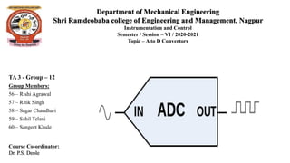
  • 5. Fig 1: Working of ADC’s
  • 6. There are basically five major types of ADCs in use today: Successive Approximation (SAR) ADC Delta-sigma (ΔΣ) ADC Dual Slope ADC Pipelined ADC Flash ADC
  • 7.
  • 8. The “bread and butter” ADC of the DAQ world is the SAR ADC (Successive Approximation Register). It offers an excellent balance of speed and resolution and handles a wide variety of signals with excellent fidelity. Advantages: Simple circuit with only one comparator needed Higher sample rates possible compared to delta-sigma ADCs Handles natural and unnatural waveshapes well Disadvantages Anti-aliasing filtering must be added externally Bit resolution and dynamic range limited compared to delta-sigma ADCs Applications Applications for SAR ADCs include DAQ systems, from low-end multiplexed ADC systems to higher speed single ADC per channel systems, industrial control and measurement, CMOS imaging.
  • 9. A newer ADC design is the delta-sigma ADC (or delta converter), which takes advantage of DSP technology in order to improve amplitude axis resolution and reduce the high-frequency quantization noise inherent in SAR designs. The complex and powerful design of delta-sigma ADCs makes them ideal for dynamic applications that require as much amplitude axis resolution as possible. This is why they are commonly found in audio, sound and vibration, and a wide range of high-end data acquisition applications and in precision industrial measurement applications. Advantages High-resolution output (24-bits) Over-sampling reduces quantization noise Inherent Anti-aliasing filtering Disadvantages Limited to around 200 kS/s sample rate Do not handle unnatural shape waveforms as well as SAR Applications Applications for Delta-sigma ADCs include data acquisition, especially noise and vibration, industrial balancing, torsional and rotational vibration, power quality monitoring, precision industrial measurements, audio and voiceband, communications.
  • 10. Fig 2: SAR Block Diagram Fig 3: Delta Sigma ADC Block DIagram
  • 11. Dual slope ADCs are accurate but not terribly fast. The principle way they convert analog to digital values is by using an integrator. The voltage is input and allowed to “run up” for a period of time. Then a known voltage of the opposite polarity is applied and allowed to run back down to zero. When it reaches zero, the system calculates what the input voltage had been by comparing the run-up time with the run-down time, and by knowing what the reference had been. The run-up and run- down times are the two slopes for which this technique has been named. • Very precise and accurate measurements Advantages • Slow conversion time due to the ramp-up and ramp-down iteration Disadvantages • Applications for dual slope ADCs include handheld and benchtop multimeters. Applications
  • 12. • Flash ADCs are fast and operate virtually without latency, which is why they are the architecture of choice when the highest possible sample rates are needed. They convert analog to a digital signal by comparing it with known reference values. The more known references that are used in the conversion process, the more accuracy can be achieved. For example, if we want a Flash ADC with a 10-bit resolution, we would need to compare the incoming analog signal against 1024 known values. The 8-bit resolution would require 256 known values, and so on. • Advantages • Fastest ADC type • Instant conversion without latency • Disadvantages • Circuit gets bigger and more power-consuming with each bit • The resolution effectively limited to 8-bit • Applications • Applications for Flash ADCs include the fastest digital oscilloscopes, microwave measurements, fiber optics, RADAR detection, and wideband radio
  • 13. Fig 4: Dual Slope ADC Fig 5: Flash ADC
  • 14. • For applications that require higher sample rates than SAR and delta-sigma ADCs can provide, but which do not require the ultra-high-speed of the Flash ADCs, we have Pipelined ADCs. • As discussed in the previous section, in a Flash ADC, the comparators are all latched simultaneously, hence the lack of latency. But this requires a lot of energy - especially when more and more comparators are used to achieve higher bit resolution. However, in a Pipelined ADC, the analog signal is not latched by all comparators at the same time, spreading out the energy required to convert the analog to a digital value. Hence the flash comparators are “pipelined” into a quasi-serial process of 2-3 cycles. This has the benefit of allowing higher resolutions to be achieved without huge energy, but it imposes two penalties: sample rates cannot be as high as a pure Flash approach, and there is a latency of typically of 3 cycles. This can be mitigated somewhat, but can never be completely eliminated. • Advantages • Almost as fast as a pure Flash ADC type (faster than SAR and Delta-sigma) • Cons • Latency due to serial “pipelined” conversion process • Maximum sample rate limited by bit resolution • Applications • Applications for Pipelined ADCs include digital oscilloscopes, RADAR, software radios, spectrum analyzers, HD video, ultrasonic imaging, digital receivers, cable modems, and Ethernet.
  • 16. Each ADC technology has its place. And because applications are so different, it is impossible to say one is better than another overall. However, it is absolutely possible to say one of them is better than another with respect to one or more of today’s DAQ applications requirements:
  • 17. 1) Used together with the Transducer :- Ideally, the span of the amplified sensor signal should fill this range. The voltage needed to power this device is a single 5-V supply. The amplified pressure transducer signal is connected to an ADC. Since the ADC connects to a microprocessor or DSP, final calibrations can be done in software.
  • 18. 2) Used in Computer to convert the analog signal to digital signal :- if an analog input is sent to a computer, an analog-to-digital converter (ADC) is required. This device can take an analog signal, such as an electrical current, and digitize it into a binary format that the computer can understand. A common use for an ADC is to convert analog video to a digital format.
  • 19. 3) Used in Microcontrollers :- An analog-to-digital converter (ADC) is used to convert an analog signal such as voltage to a digital form so that it can be read and processed by a microcontroller. Most microcontrollers nowadays have built-in ADC converters. It is also possible to connect an external ADC converter to any type of microcontroller.
  • 20. 4) Used in digital storage oscilloscopes :- The input signal from the attenuator and Y preamplifier is digitized by an analog to digital converter (ADC or A/D), so that it can be stored in the acquisition memory. There are two main types of ADC used in digital storage oscilloscopes: the successive approximation register (SAR) type and the flash converter.
  • 21. 5) Used in scientific instruments :- Since the real world is analog, but the computer world is binary, we need to be able to convert signals between the two. Devices that change an analog signal to a digital signal are called analog to digital converters (ADC).
  • 22. 6) Used in music reproduction technology :- ADCs may also be used to convert analog audio streams. The accuracy of the audio conversion depends on the sampling rate used in the conversion process. Higher sampling rates provide a better estimation of the analog signal, and therefore produce a higher-quality sound.
  • 23. Testing an Analog to Digital Converter requires an analog input source and hardware to send control signals and capture digital data output. Some ADCs also require an accurate source of reference signal. The key parameters to test an ADC are: • DC offset error • DC gain error • Signal to noise ratio (SNR) • Total harmonic distortion (THD) • Integral nonlinearity (INL) • Differential nonlinearity (DNL) • Spurious free dynamic range • Power dissipation
  • 24. • The fundamental 1/2-bit quantization uncertainty associated with analog-to-digital conversion, ADC testing is more difficult than DAC testing. • Owing to the need for determing both the output code and the transition point, referred to the input, rather than simply measuring an output response to a predetermined code. • The effects of noise (occurring in either the signal or the converter, or picked up in the wiring) are to introduce an uncertainty in the precise determination of the analog input values at which the output code transitions take place, and to, in effect, increase the quantization band. • The nature of these quantization and noise uncertainty errors is shown in Figure .
  • 25. • A flowchart of a calibration firmware in the AVR is given. It uses the external DAC through the test fixture and runs its own calibration algorithm. • There is no need for using several ADC channels, only switching between single ended and differential conversion. The ADC parameters are the same regardless of which channel is used. The multiplexer does not introduce any errors. • This piece of firmware is programmed into the AVR prior to calibration, and is replaced by the actual application firmware afterward. Once again, the EESAVE fuse must be programmed to preserve the calibration parameters in EEPROM during Flash reprogramming.
  • 26. • The total error of the actual ADC comes from more than just quantization error. • For most applications, the ADC needs no calibration when using single ended conversion. The typical accuracy is 1-2 LSB, and it is often neither necessary nor practical to calibrate for better accuracies. • However, when using differential conversion the situation changes, especially with high gain settings. Minor process variations are scaled with the gain stage and give large parameter differences from part to part. The uncompensated error is typically above 20 LSB. These variations must be characterized for every device and compensated for in software. • At first sight 20 LSB seems to be a large value, but using simple calibration algorithms, accuracies of typically 1-2 LSB can be achieved.
  • 27. • https://en.wikipedia.org/wiki/Analog-to-digital_converter • https://www.analog.com/media/en/training-seminars/design-handbooks/Analog-Digital- Conversion-1977/Chapter2-4.pdf • http://ww1.microchip.com/downloads/en/appnotes/atmel-2559-characterization-and- calibration-of-the-adc-on-an-avr_applicationnote_avr120.pdf • Measurement System, Application and Design, E.O. Doebelin, Mc Graw Hill Education.