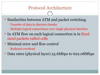
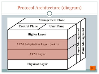
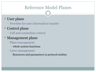
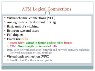
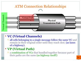
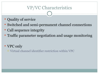
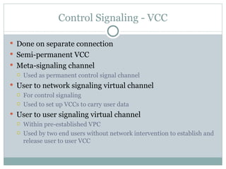
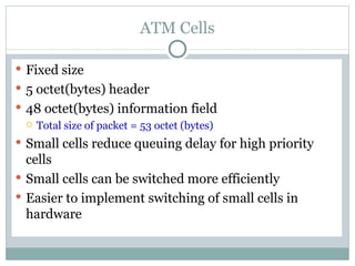
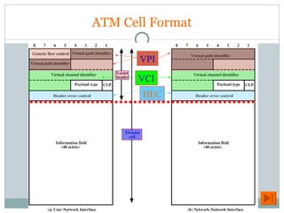
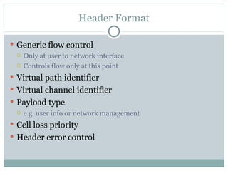
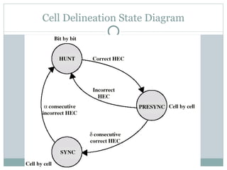
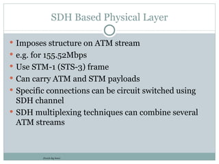
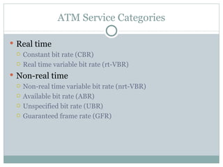
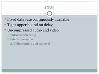
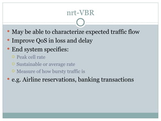
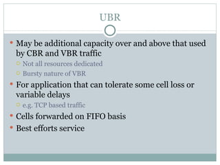
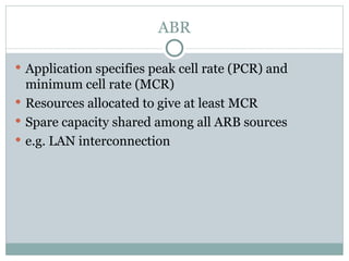
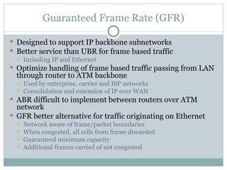
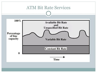
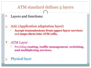
ASYNCHRONOUS TRANSFER MODE
Protocol Architecture Similarities between ATM and packet switching Transfer of data in discrete chunks Multiple logical connections over single physical interface In ATM flow on each logical connection is in  fixed sized packets called cells Minimal error and flow control Reduced overhead Data rates (physical layer) 25.6Mbps to 622.08Mbps
Protocol Architecture (diagram)
Reference Model Planes User plane Provides for user information transfer Control plane Call and connection control Management plane Plane management whole system functions Layer management Resources and parameters in protocol entities
ATM Logical Connections Virtual channel connections (VCC) Analogous to virtual circuit in X.25 Basic unit of switching Between two end users Full duplex Fixed size  cells  Frame relay  :  variable-length  packets called  frames ATM  :  fixed-length  packets called  cells  Data, user-network exchange (control) and network-network exchange (network management and routing) Virtual path connection (VPC) Bundle of VCC with same end points
ATM Connection Relationships VC (Virtual Channels) all cells belonging to a single message follow the same VC  and remain in their original order until they reach dest.  (as lanes of a highway). VP (Virtual Path) a  combination of VCs  that bundled together because part of their paths are the same  (as highway itself!)
Advantages of Virtual Paths Simplified network architecture Increased network performance and reliability Reduced processing Short connection setup time Enhanced network services
VP/VC Characteristics Quality of service Switched and semi-permanent channel connections Call sequence integrity Traffic parameter negotiation and usage monitoring VPC only Virtual channel identifier restriction within VPC
Control Signaling - VCC Done on separate connection Semi-permanent VCC Meta-signaling channel Used as permanent control signal channel User to network signaling virtual channel For control signaling Used to set up VCCs to carry user data User to user signaling virtual channel Within pre-established VPC Used by two end users without network intervention to establish and release user to user VCC
ATM Cells Fixed size 5 octet(bytes) header 48 octet(bytes) information field Total size of packet = 53 octet (bytes) Small cells reduce queuing delay for high priority cells Small cells can be switched more efficiently Easier to implement switching of small cells in hardware
ATM Cell Format VPI VCI HEC
Header Format Generic flow control Only at user to network interface Controls flow only at this point Virtual path identifier Virtual channel identifier Payload type e.g. user info or network management Cell loss priority Header error control
Generic Flow Control (GFC) Control traffic flow at user to network interface (UNI) to alleviate short term overload Two sets of procedures Uncontrolled transmission Controlled transmission Every connection either subject to flow control or not Subject to flow control May be one group (A) default May be two groups (A and B) Flow control is from subscriber to network Controlled by network side
Header Error Control 8 bit error control field Calculated on remaining 32 bits of header Allows some error correction
HEC Operation at Receiver
Effect of  Error in  Cell Header
Impact of Random Bit Errors  on HEC Performance
Transmission of ATM Cells 622.08Mbps 155.52Mbps 51.84Mbps 25.6Mbps Cell Based physical layer SDH based physical layer
Cell Based Physical Layer No framing imposed Continuous stream of 53 octet cells Cell delineation based on header error control field
Cell Delineation State Diagram
SDH Based Physical Layer Imposes structure on ATM stream e.g. for 155.52Mbps Use STM-1 (STS-3) frame Can carry ATM and STM payloads Specific connections can be circuit switched using SDH channel SDH multiplexing techniques can combine several ATM streams (Synch dig hierc)
ATM Service Categories Real time Constant bit rate (CBR) Real time variable bit rate (rt-VBR) Non-real time Non-real time variable bit rate (nrt-VBR) Available bit rate (ABR) Unspecified bit rate (UBR) Guaranteed frame rate (GFR)
CBR Fixed data rate continuously available Tight upper bound on delay Uncompressed audio and video Video conferencing Interactive audio A/V distribution and retrieval
rt-VBR Time sensitive application Tightly constrained delay and delay variation rt-VBR applications transmit at a rate that varies with time e.g. compressed video  Produces varying sized image frames Original (uncompressed) frame rate constant So compressed data rate varies Can statistically multiplex connections
nrt-VBR May be able to characterize expected traffic flow Improve QoS in loss and delay End system specifies: Peak cell rate  Sustainable or average rate  Measure of how bursty traffic is e.g. Airline reservations, banking transactions
UBR May be additional capacity over and above that used by CBR and VBR traffic Not all resources dedicated Bursty nature of VBR For application that can tolerate some cell loss or variable delays e.g. TCP based traffic Cells forwarded on FIFO basis Best efforts service
ABR Application specifies peak cell rate (PCR) and minimum cell rate (MCR) Resources allocated to give at least MCR Spare capacity shared among all ARB sources e.g. LAN interconnection
Guaranteed Frame Rate (GFR) Designed to support IP backbone subnetworks Better service than UBR for frame based traffic Including IP and Ethernet Optimize handling of frame based traffic passing from LAN through router to ATM backbone Used by enterprise, carrier and ISP networks Consolidation and extension of IP over WAN ABR difficult to implement between routers over ATM network GFR better alternative for traffic originating on Ethernet Network aware of frame/packet boundaries When congested, all cells from frame discarded Guaranteed minimum capacity Additional frames carried of not congested
ATM Bit Rate Services
ATM standard defines 3 layers Layers and functions: AAL (Application adaptation layer) Accept transmissions from upper-layer services  and  maps them into ATM cells. ATM Layer Providing  routing, traffic management, switching, and multiplexing services. Physical layer
Segmentation and Reassembly PDU
AAL Type 1 Supports app. that transfer info at  constant bit rates  ,eg. video and voice If data is long    divided into 47 bytes long data    + 1 byte(8 bits)  header Passed to ATM layer = 48-byte data unit
Example of calculation An AAL1 layer receives data at 2Mbps. How many cells are created per second by the ATM layer? Solution: 2M / 8 bits = 250,000 bytes per second 250,000 byte / 47 bytes = 5319.14 = 5320 ATM cells
AAL Type 2 Support variable bit-rate app. If data is long    divided into 45 bytes long data    + 1 byte(8 bits)  header    + 2 bytes  trailer Passed to ATM layer = 48-byte data unit
AAL Type 3/4 Support connection-oriented and connectionless data services Limitation : receive data packet <= 65,535 bytes   Data divided into   44-byte long data  + 4-byte  header  (at beginning of message)  + padding (if necessary )= 0-43 bytes + 4-byte  trailer  (at end of message)  Passed to ATM layer  First, 4-byte(16 bits) header  In the middle = 44-byte data unit (until finished) Padding (if necessary )= 0-43 bytes Finally, 4-byte trailer
AAL Type 5 Support app. where transmissions are not route through multiple nodes @ multiplexed with other transmission Sequencing & error correction mechanisms are unnecessary overhead (in front) Limitation : receive data packet <= 65,535 bytes  Data divided into   48-byte long data  + padding (if necessary )= 0-47 bytes + 8-byte  trailer  (at end of message)  Passed to ATM layer  First, 44-byte data unit (until finished) Padding (if necessary )= 0-47 bytes Finally, 8-byte trailer

13 atm

  • 1.
  • 2.
    Protocol Architecture Similaritiesbetween ATM and packet switching Transfer of data in discrete chunks Multiple logical connections over single physical interface In ATM flow on each logical connection is in fixed sized packets called cells Minimal error and flow control Reduced overhead Data rates (physical layer) 25.6Mbps to 622.08Mbps
  • 3.
  • 4.
    Reference Model PlanesUser plane Provides for user information transfer Control plane Call and connection control Management plane Plane management whole system functions Layer management Resources and parameters in protocol entities
  • 5.
    ATM Logical ConnectionsVirtual channel connections (VCC) Analogous to virtual circuit in X.25 Basic unit of switching Between two end users Full duplex Fixed size cells Frame relay : variable-length packets called frames ATM : fixed-length packets called cells Data, user-network exchange (control) and network-network exchange (network management and routing) Virtual path connection (VPC) Bundle of VCC with same end points
  • 6.
    ATM Connection RelationshipsVC (Virtual Channels) all cells belonging to a single message follow the same VC and remain in their original order until they reach dest. (as lanes of a highway). VP (Virtual Path) a combination of VCs that bundled together because part of their paths are the same (as highway itself!)
  • 7.
    Advantages of VirtualPaths Simplified network architecture Increased network performance and reliability Reduced processing Short connection setup time Enhanced network services
  • 8.
    VP/VC Characteristics Qualityof service Switched and semi-permanent channel connections Call sequence integrity Traffic parameter negotiation and usage monitoring VPC only Virtual channel identifier restriction within VPC
  • 9.
    Control Signaling -VCC Done on separate connection Semi-permanent VCC Meta-signaling channel Used as permanent control signal channel User to network signaling virtual channel For control signaling Used to set up VCCs to carry user data User to user signaling virtual channel Within pre-established VPC Used by two end users without network intervention to establish and release user to user VCC
  • 10.
    ATM Cells Fixedsize 5 octet(bytes) header 48 octet(bytes) information field Total size of packet = 53 octet (bytes) Small cells reduce queuing delay for high priority cells Small cells can be switched more efficiently Easier to implement switching of small cells in hardware
  • 11.
    ATM Cell FormatVPI VCI HEC
  • 12.
    Header Format Genericflow control Only at user to network interface Controls flow only at this point Virtual path identifier Virtual channel identifier Payload type e.g. user info or network management Cell loss priority Header error control
  • 13.
    Generic Flow Control(GFC) Control traffic flow at user to network interface (UNI) to alleviate short term overload Two sets of procedures Uncontrolled transmission Controlled transmission Every connection either subject to flow control or not Subject to flow control May be one group (A) default May be two groups (A and B) Flow control is from subscriber to network Controlled by network side
  • 14.
    Header Error Control8 bit error control field Calculated on remaining 32 bits of header Allows some error correction
  • 15.
  • 16.
    Effect of Error in Cell Header
  • 17.
    Impact of RandomBit Errors on HEC Performance
  • 18.
    Transmission of ATMCells 622.08Mbps 155.52Mbps 51.84Mbps 25.6Mbps Cell Based physical layer SDH based physical layer
  • 19.
    Cell Based PhysicalLayer No framing imposed Continuous stream of 53 octet cells Cell delineation based on header error control field
  • 20.
  • 21.
    SDH Based PhysicalLayer Imposes structure on ATM stream e.g. for 155.52Mbps Use STM-1 (STS-3) frame Can carry ATM and STM payloads Specific connections can be circuit switched using SDH channel SDH multiplexing techniques can combine several ATM streams (Synch dig hierc)
  • 22.
    ATM Service CategoriesReal time Constant bit rate (CBR) Real time variable bit rate (rt-VBR) Non-real time Non-real time variable bit rate (nrt-VBR) Available bit rate (ABR) Unspecified bit rate (UBR) Guaranteed frame rate (GFR)
  • 23.
    CBR Fixed datarate continuously available Tight upper bound on delay Uncompressed audio and video Video conferencing Interactive audio A/V distribution and retrieval
  • 24.
    rt-VBR Time sensitiveapplication Tightly constrained delay and delay variation rt-VBR applications transmit at a rate that varies with time e.g. compressed video Produces varying sized image frames Original (uncompressed) frame rate constant So compressed data rate varies Can statistically multiplex connections
  • 25.
    nrt-VBR May beable to characterize expected traffic flow Improve QoS in loss and delay End system specifies: Peak cell rate Sustainable or average rate Measure of how bursty traffic is e.g. Airline reservations, banking transactions
  • 26.
    UBR May beadditional capacity over and above that used by CBR and VBR traffic Not all resources dedicated Bursty nature of VBR For application that can tolerate some cell loss or variable delays e.g. TCP based traffic Cells forwarded on FIFO basis Best efforts service
  • 27.
    ABR Application specifiespeak cell rate (PCR) and minimum cell rate (MCR) Resources allocated to give at least MCR Spare capacity shared among all ARB sources e.g. LAN interconnection
  • 28.
    Guaranteed Frame Rate(GFR) Designed to support IP backbone subnetworks Better service than UBR for frame based traffic Including IP and Ethernet Optimize handling of frame based traffic passing from LAN through router to ATM backbone Used by enterprise, carrier and ISP networks Consolidation and extension of IP over WAN ABR difficult to implement between routers over ATM network GFR better alternative for traffic originating on Ethernet Network aware of frame/packet boundaries When congested, all cells from frame discarded Guaranteed minimum capacity Additional frames carried of not congested
  • 29.
    ATM Bit RateServices
  • 30.
    ATM standard defines3 layers Layers and functions: AAL (Application adaptation layer) Accept transmissions from upper-layer services and maps them into ATM cells. ATM Layer Providing routing, traffic management, switching, and multiplexing services. Physical layer
  • 31.
  • 32.
    AAL Type 1Supports app. that transfer info at constant bit rates ,eg. video and voice If data is long  divided into 47 bytes long data + 1 byte(8 bits) header Passed to ATM layer = 48-byte data unit
  • 33.
    Example of calculationAn AAL1 layer receives data at 2Mbps. How many cells are created per second by the ATM layer? Solution: 2M / 8 bits = 250,000 bytes per second 250,000 byte / 47 bytes = 5319.14 = 5320 ATM cells
  • 34.
    AAL Type 2Support variable bit-rate app. If data is long  divided into 45 bytes long data + 1 byte(8 bits) header + 2 bytes trailer Passed to ATM layer = 48-byte data unit
  • 35.
    AAL Type 3/4Support connection-oriented and connectionless data services Limitation : receive data packet <= 65,535 bytes Data divided into  44-byte long data + 4-byte header (at beginning of message) + padding (if necessary )= 0-43 bytes + 4-byte trailer (at end of message) Passed to ATM layer First, 4-byte(16 bits) header In the middle = 44-byte data unit (until finished) Padding (if necessary )= 0-43 bytes Finally, 4-byte trailer
  • 36.
    AAL Type 5Support app. where transmissions are not route through multiple nodes @ multiplexed with other transmission Sequencing & error correction mechanisms are unnecessary overhead (in front) Limitation : receive data packet <= 65,535 bytes Data divided into  48-byte long data + padding (if necessary )= 0-47 bytes + 8-byte trailer (at end of message) Passed to ATM layer First, 44-byte data unit (until finished) Padding (if necessary )= 0-47 bytes Finally, 8-byte trailer