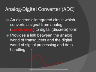
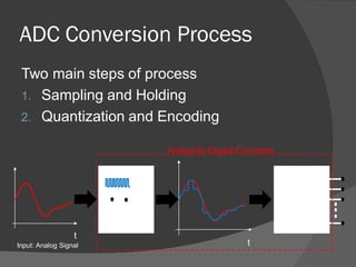
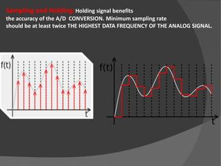
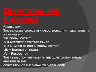
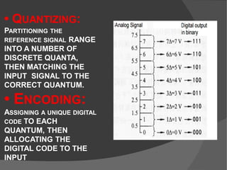
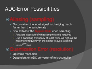
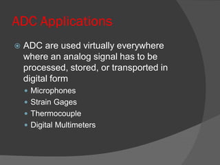
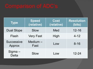
 What is ADC?
 Conversion Process
 Accuracy
 Examples of ADC applications
Signal Types
Analog Signals
 Any continuous signal that
a time varying variable of
the signal is a
representation of some
other time varying quantity
 Measures one quantity in
terms of some other quantity
 Examples
○ Speedometer needle as
function of speed
○ Radio volume as function of
knob movement
t
Signal Types
Digital Signals
 Consist of only two
states
 Binary States
 On and off
 Computers can only
perform processing on
digitized signals
0
1
Analog-Digital Converter (ADC)
 An electronic integrated circuit which
converts a signal from analog
(continuous) to digital (discrete) form
 Provides a link between the analog
world of transducers and the digital
world of signal processing and data
handling
ADC Conversion Process
Two main steps of process
1. Sampling and Holding
2. Quantization and Encoding
t
tInput: Analog Signal
Sampling and
Hold
Quantizing
and
Encoding
Analog-to-Digital Converter
Sampling and Holding:Holding signal benefits
the accuracy of the A/D CONVERSION. Minimum sampling rate
should be at least twice THE HIGHEST DATA FREQUENCY OF THE ANALOG SIGNAL.
QUANTIZING AND
ENCODING
RESOLUTION:
THE SMALLEST CHANGE IN ANALOG SIGNAL THAT WILL RESULT IN
A CHANGE IN
THE DIGITAL OUTPUT.
V = REFERENCE VOLTAGE RANGE
N = NUMBER OF BITS IN DIGITAL OUTPUT.
2N = NUMBER OF STATES.
∆V = RESOLUTION
THE RESOLUTION REPRESENTS THE QUANTIZATION ERROR
INHERENT IN THE
CONVERSION OF THE SIGNAL TO DIGITAL FORM
• QUANTIZING:
PARTITIONING THE
REFERENCE SIGNAL RANGE
INTO A NUMBER OF
DISCRETE QUANTA,
THEN MATCHING THE
INPUT SIGNAL TO THE
CORRECT QUANTUM.
• ENCODING:
ASSIGNING A UNIQUE DIGITAL
CODE TO EACH
QUANTUM, THEN
ALLOCATING THE
DIGITAL CODE TO THE
INPUT
ADC-Error Possibilities
Aliasing (sampling)
 Occurs when the input signal is changing much
faster than the sample rate
 Should follow the Nyquist Rule when sampling
○ Answers question of what sample rate is required
○ Use a sampling frequency at least twice as high as the
maximum frequency in the signal to avoid aliasing
○ fsample>2*fsignal
Quantization Error (resolution)
 Optimize resolution
 Dependent on ADC converter of microcontoller
ADC Applications
 ADC are used virtually everywhere
where an analog signal has to be
processed, stored, or transported in
digital form
 Microphones
 Strain Gages
 Thermocouple
 Digital Multimeters
Comparison of ADC’s
Type
Speed
(relative)
Cost
(relative)
Resolution
(bits)
Dual Slope Slow Med 12-16
Flash Very Fast High 4-12
Successive
Approx
Medium –
Fast
Low 8-16
Sigma –
Delta
Slow Low 12-24
ADC Subsystem of MC9S12C32
Input Pins
ADC Built-into
MC9S12C32
Presenter: Ehsan Maleki

ADC - Analog digital converter

  • 2.
     What isADC?  Conversion Process  Accuracy  Examples of ADC applications
  • 3.
    Signal Types Analog Signals Any continuous signal that a time varying variable of the signal is a representation of some other time varying quantity  Measures one quantity in terms of some other quantity  Examples ○ Speedometer needle as function of speed ○ Radio volume as function of knob movement t
  • 4.
    Signal Types Digital Signals Consist of only two states  Binary States  On and off  Computers can only perform processing on digitized signals 0 1
  • 5.
    Analog-Digital Converter (ADC) An electronic integrated circuit which converts a signal from analog (continuous) to digital (discrete) form  Provides a link between the analog world of transducers and the digital world of signal processing and data handling
  • 6.
    ADC Conversion Process Twomain steps of process 1. Sampling and Holding 2. Quantization and Encoding t tInput: Analog Signal Sampling and Hold Quantizing and Encoding Analog-to-Digital Converter
  • 7.
    Sampling and Holding:Holdingsignal benefits the accuracy of the A/D CONVERSION. Minimum sampling rate should be at least twice THE HIGHEST DATA FREQUENCY OF THE ANALOG SIGNAL.
  • 8.
    QUANTIZING AND ENCODING RESOLUTION: THE SMALLESTCHANGE IN ANALOG SIGNAL THAT WILL RESULT IN A CHANGE IN THE DIGITAL OUTPUT. V = REFERENCE VOLTAGE RANGE N = NUMBER OF BITS IN DIGITAL OUTPUT. 2N = NUMBER OF STATES. ∆V = RESOLUTION THE RESOLUTION REPRESENTS THE QUANTIZATION ERROR INHERENT IN THE CONVERSION OF THE SIGNAL TO DIGITAL FORM
  • 9.
    • QUANTIZING: PARTITIONING THE REFERENCESIGNAL RANGE INTO A NUMBER OF DISCRETE QUANTA, THEN MATCHING THE INPUT SIGNAL TO THE CORRECT QUANTUM. • ENCODING: ASSIGNING A UNIQUE DIGITAL CODE TO EACH QUANTUM, THEN ALLOCATING THE DIGITAL CODE TO THE INPUT
  • 10.
    ADC-Error Possibilities Aliasing (sampling) Occurs when the input signal is changing much faster than the sample rate  Should follow the Nyquist Rule when sampling ○ Answers question of what sample rate is required ○ Use a sampling frequency at least twice as high as the maximum frequency in the signal to avoid aliasing ○ fsample>2*fsignal Quantization Error (resolution)  Optimize resolution  Dependent on ADC converter of microcontoller
  • 11.
    ADC Applications  ADCare used virtually everywhere where an analog signal has to be processed, stored, or transported in digital form  Microphones  Strain Gages  Thermocouple  Digital Multimeters
  • 12.
    Comparison of ADC’s Type Speed (relative) Cost (relative) Resolution (bits) DualSlope Slow Med 12-16 Flash Very Fast High 4-12 Successive Approx Medium – Fast Low 8-16 Sigma – Delta Slow Low 12-24
  • 13.
    ADC Subsystem ofMC9S12C32 Input Pins ADC Built-into MC9S12C32 Presenter: Ehsan Maleki