Downloaded 102 times


![Effect of Amplitude Quantization
code
w idth
analog input
110
1/8
- Q/2
111
0 3/8
(a)
2/8
000
6/8
010
1 LSB
5/8
analog input
7/8
001
4/8
011
(b)
101
+ Q/2
FS
digital
output
100
• Quantization noise
• For full-scale sine wave to n-bit ADC, the SNR = (6.02 n + 1.76) dB
• For one bit increase SNR increases by 7.78 dB
• By increasing sampling freq by a factor of k and filtering noise,
The SNR improves to, SNR = [6.02 n + 1.76 + 10 log10 (k)] dB
fA S
signal
S
frequency band
of interest
quantization noise
fS
am plitude
average noise
level
S
am plitude
f / 2
f / 2 k f / 2
A
signal
frequency band
of interest
average noise
level
f S
k f
N. Mathivanan](https://image.slidesharecdn.com/adcanddaq-160409131049/75/Analog-to-Digital-Converters-and-Data-Acquisition-Systems-16-2048.jpg)


![• Oversampling
o For full-scale sine wave to n-bit ADC, the SNR = (6.02 n + 1.76) dB
o For one bit increase SNR increases by 7.78 dB
o By increasing sampling frequency by a factor of k and filtering noise,
o The SNR improves to, SNR = [6.02 n + 1.76 + 10 log10 (k)] dB
o Oversampling by 4 times improves SNR by 6 dB
o Max. sampling rate limited & is set by ADC
Principles of Operation – Oversampling & Noise Shaping
N. Mathivanan](https://image.slidesharecdn.com/adcanddaq-160409131049/75/Analog-to-Digital-Converters-and-Data-Acquisition-Systems-21-2048.jpg)


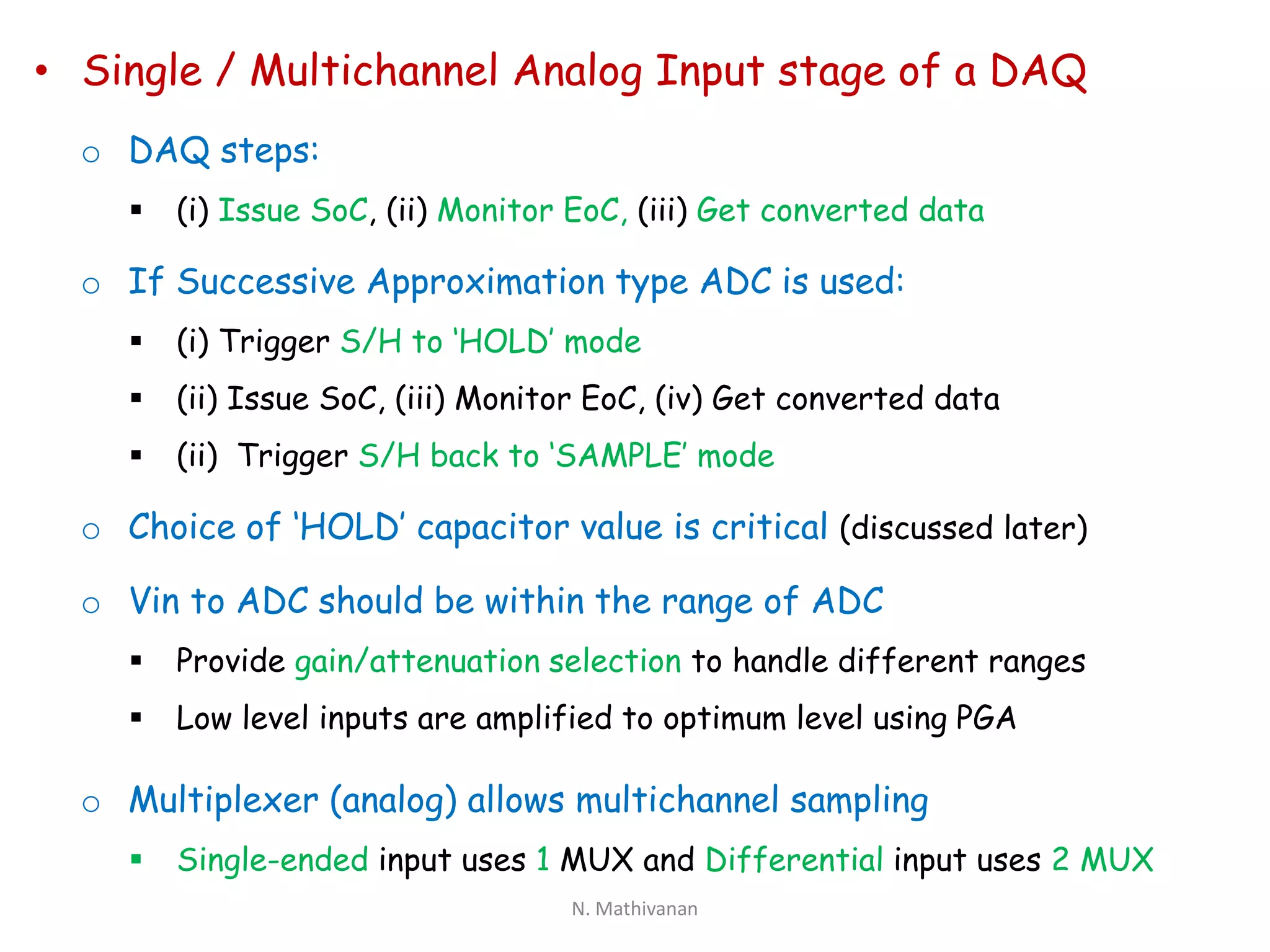


This document discusses principles of data acquisition systems and analog-to-digital converters. It describes the basic functions of data acquisition systems including analog input, output, and digital and timing I/O. It then discusses analog-to-digital converter types including integration, successive approximation, flash, and sigma-delta converters. It covers characteristics, principles of operation, advantages and disadvantages of each type. Finally, it outlines the functional blocks of a typical data acquisition system including specification parameters and the analog input stage.


