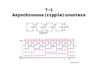
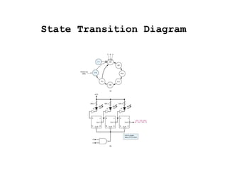
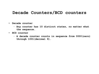
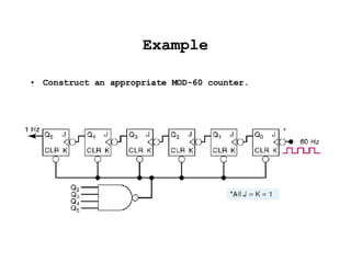
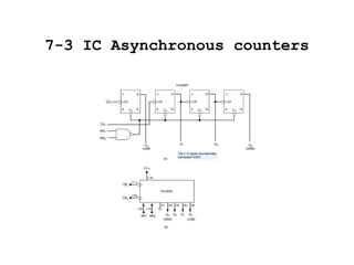
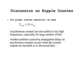
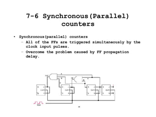
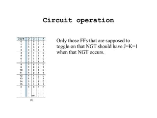
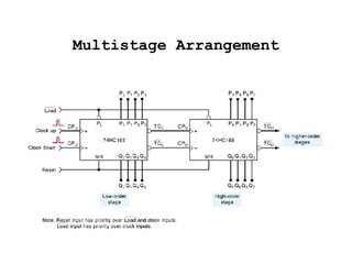
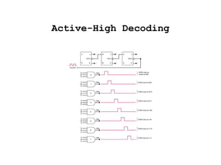
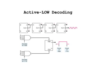
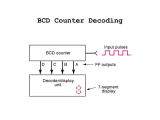
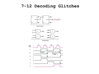
This document discusses different types of counters including asynchronous (ripple) counters, synchronous counters, down counters, and shift-register counters. It provides examples of how to construct various counters using flip-flops and logic gates. It also covers decoding the output states of counters and issues that can arise from propagation delays in asynchronous counters.

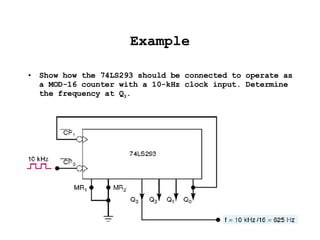
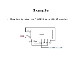
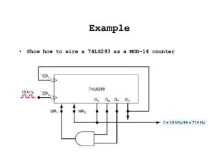
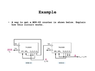


![[IJET V2I3P1] Authors: G Hemanth kumar Dr. M. Saravanan, Charan kumar. K](https://cdn.slidesharecdn.com/ss_thumbnails/ijet-v2i3p1-160609050730-thumbnail.jpg?width=640&height=640&fit=bounds)


