Downloaded 291 times

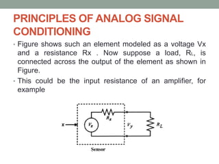
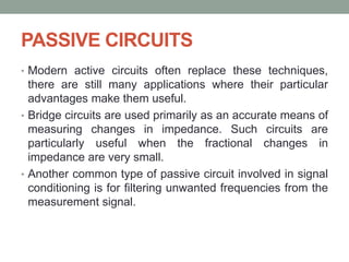
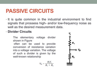
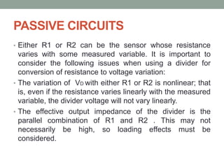


The document discusses analog signal conditioning, which involves modifying signals for compatibility with various components in process-control applications. Key concepts include level adjustment, amplification, linearization, filtering, and impedance matching, as well as the use of circuits like Wheatstone bridges and RC filters. It highlights the importance of accurately converting signals for digital interfaces and managing loading effects to ensure precise measurements.


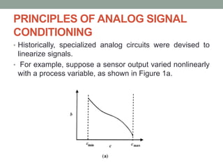
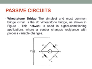
![Sensor Technology Lecture 6 [Autosaved].pptx](https://cdn.slidesharecdn.com/ss_thumbnails/lecture6autosaved-250626060615-a31db175-thumbnail.jpg?width=640&height=640&fit=bounds)


