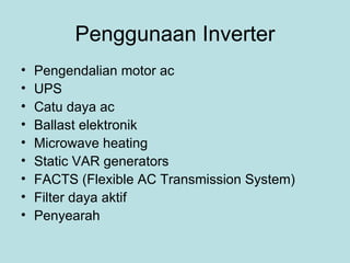
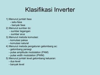
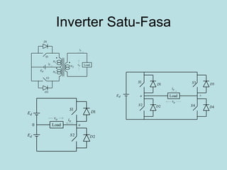
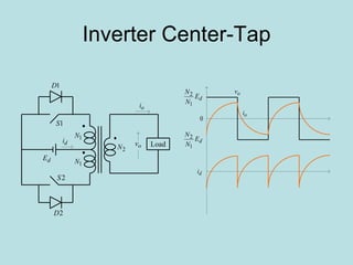
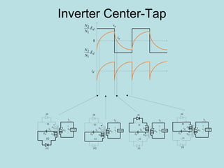
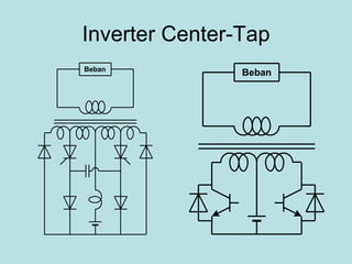
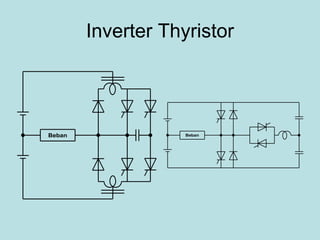
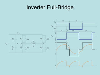
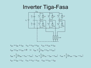
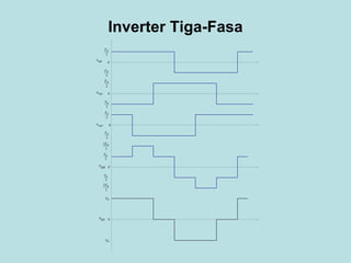
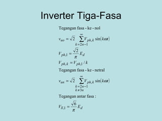
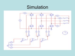
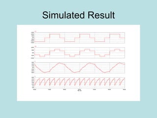
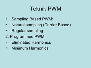
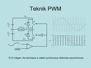
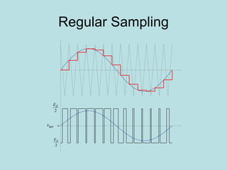
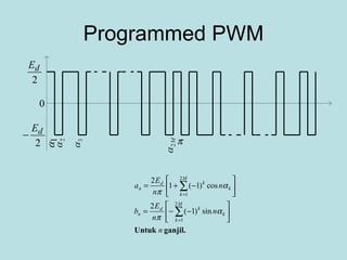
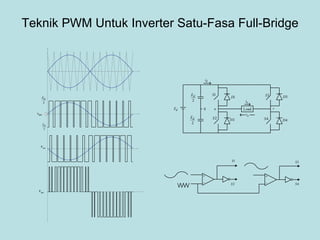
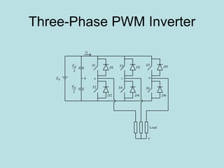
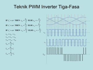
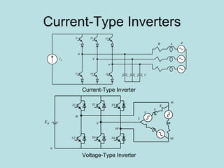
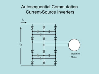
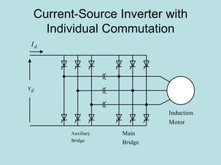
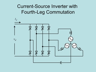
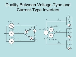
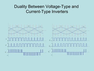
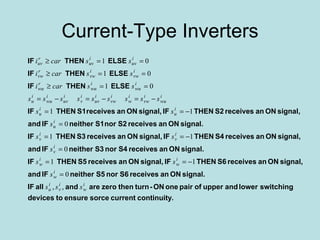
Inverter (Konverter DC – AC) Pekik Argo Dahono
Penggunaan Inverter Pengendalian motor ac UPS Catu daya ac Ballast elektronik Microwave heating Static VAR generators FACTS (Flexible AC Transmission System) Filter daya aktif Penyearah
Variable Speed Drives
Uninterruptibe AC Power Supplies
Basic Concepts
Properties of Ideal Inverters DC input is free of ripple AC output is sinusoidal or has a controllable waveshape
Klasifikasi Inverter 1) Menurut jumlah fasa - satu-fasa - banyak fasa 2) Menurut sumber dc: - sumber tegangan - sumber arus 3) Menurut metoda komutasi: - komutasi paksa - komutasi natural 4) Menurut metoda pengaturan gelombang ac: - gelombang persegi - pulse amplitude modulation (PAM) - pulse width modulation (PWM) 5) Menurut jumlah level gelombang keluaran: - dua level - banyak level
Inverter Satu-Fasa
Inverter Center-Tap
Inverter Center-Tap
Inverter Center-Tap
Analisis Tegangan Output Inverter Center-Tap
Inverter Center-Tap Sederhana Komponen minimum Harus pakai trafo Cocok untuk daya rendah (< 1 kW) Cocok untuk tegangan dc yang rendah Pengaturan tegangan dilakukan dengan menggunakan trafo ferroresonance.
Half-Bridge Inverter
Analisis Tegangan Output Inverter Half-Bridge
Inverter Thyristor
Inverter Thyristor
Inverter Full-Bridge
Inverter Tiga-Fasa
Inverter Tiga-Fasa
Inverter Tiga-Fasa
Simulation
Simulated Result
Teknik PWM Sampling Based PWM: Natural sampling (Carrier Based) Regular sampling  2. Programmed PWM: Eliminated Harmonics Minimum Harmonics
Teknik PWM If f c /f r  integer, the technique is called synchronous otherwise asynchronous
Regular Sampling
Simulation
Simulation Results
Analisis Tegangan Keluaran nverter PWM Satu-Fasa
Simulation result under nonsinusoidal reference
Analisis Tegangan keluaran Maximum peak output voltage is  E d /2.  This value is less than the fundamental component of square-wave output voltage. The output current waveform is almost sinusoidal when the switching frequency is high. Because the switching frequency is high, the switching losses are also high.
Analisis Riak
Analisis Riak
Programmed PWM
Teknik PWM Untuk Inverter Satu-Fasa Full-Bridge
Three-Phase PWM Inverter
Teknik PWM Inverter Tiga-Fasa
Simulation
Simulation Results
Teknik PWM Inverter Tiga-Fasa
Simulation Result
Switching Function Concept
Current-Type Inverters Current-Type Inverter Voltage-Type Inverter
Autosequential Commutation  Current-Source Inverters
Current-Source Inverter with Individual Commutation
Current-Source Inverter with  Fourth-Leg Commutation
Duality Between Voltage-Type and Current-Type Inverters
Duality Between Voltage-Type and  Current-Type Inverters
Current-Type Inverters
Current-Type Inverters At present, voltage-type inverters are more popular than current-type inverters. Current-type inverters are commonly used as PWM rectifiers. Advances on superconductor will increase the use of current-type inverters. At present, several manufacturers introduce reverse-blocking devices on one module.  Current-type inverters are introduced for medium voltage ac drives because the input and output currents are almost sinusoidal, inherently four-quadrants, and short-circuit proof.
Space-Vector PWM
Space Vector PWM
Space Vector PWM
Two-Level Inverters High-voltage applications need high-voltage switching devices. Series connection of switching devices are difficult to control. Output waveforms can only be improved at the expense of switching losses. High-voltage applications may need bulky and expensive transformers.
Diode clamped multilevel inverters Three-level inverter Five-level inverter
Flying capacitor inverters Three level inverters Five level
Cascade connection of single-phase inverters Three level inverter Five level inverter

Inverters