Download as PDF, PPTX
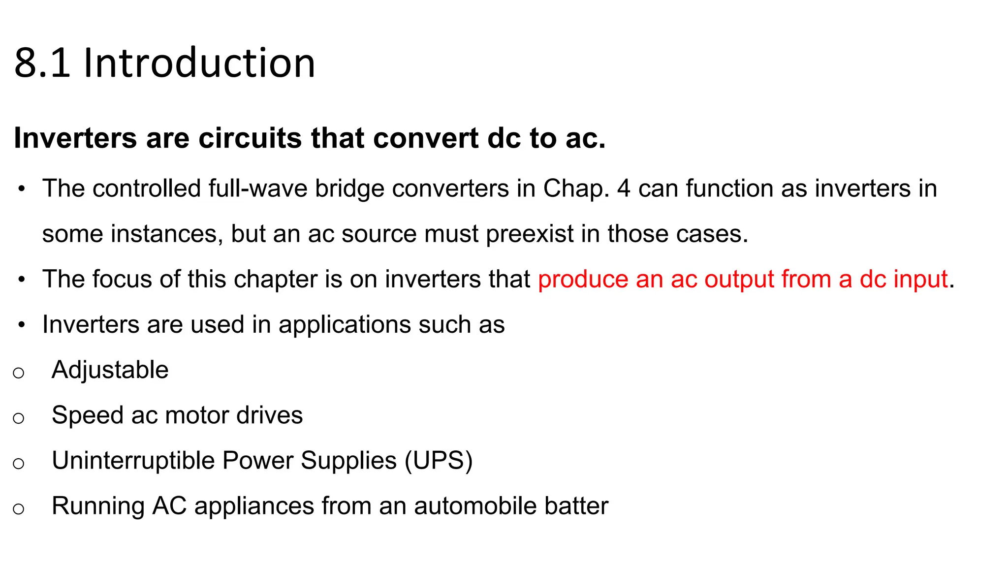
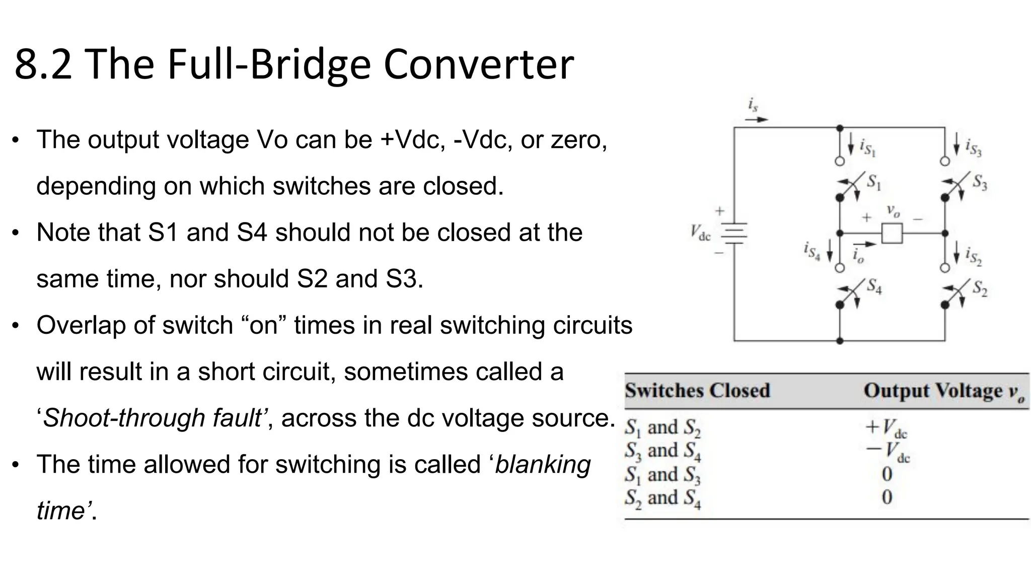
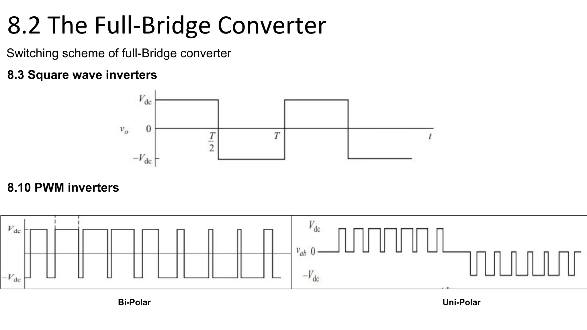
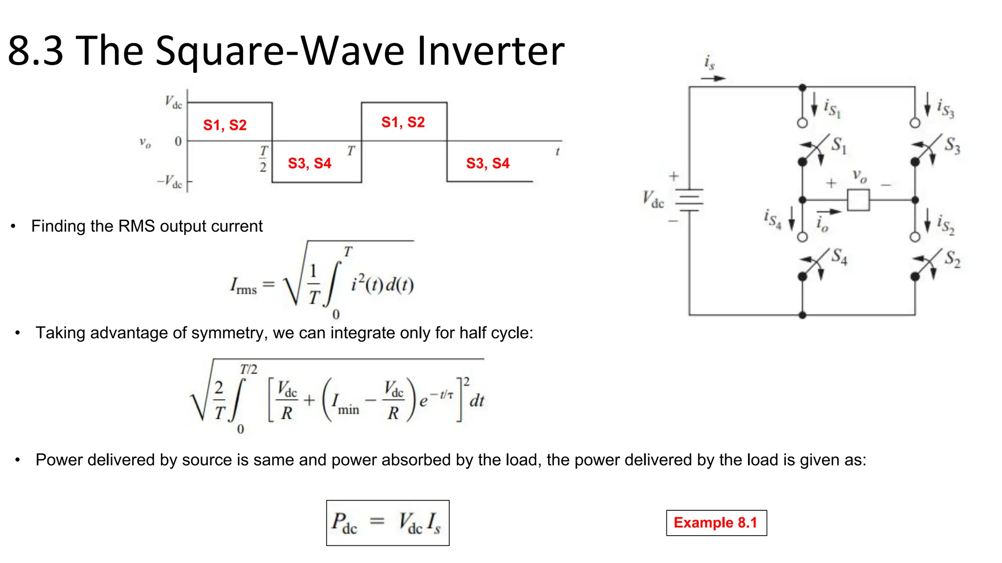
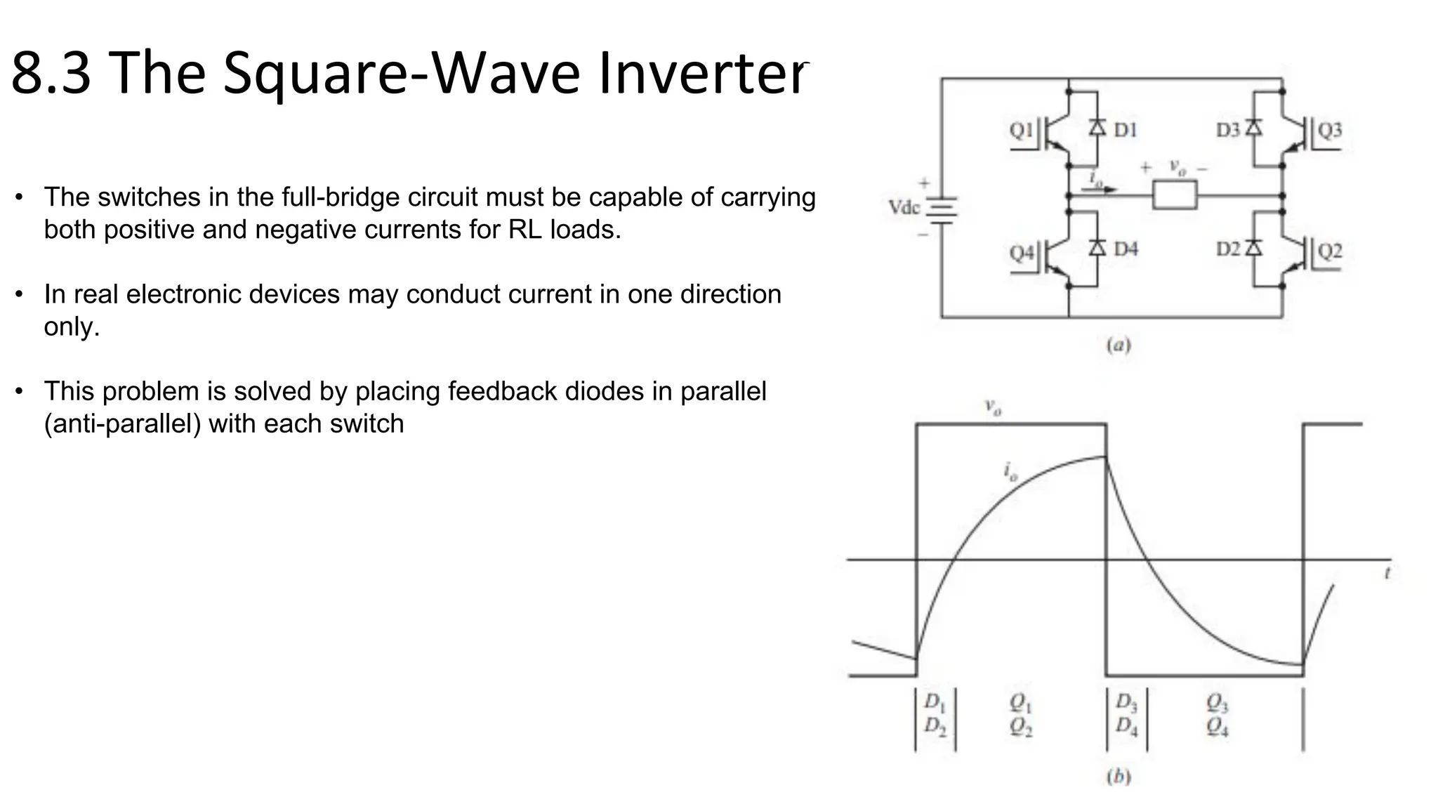
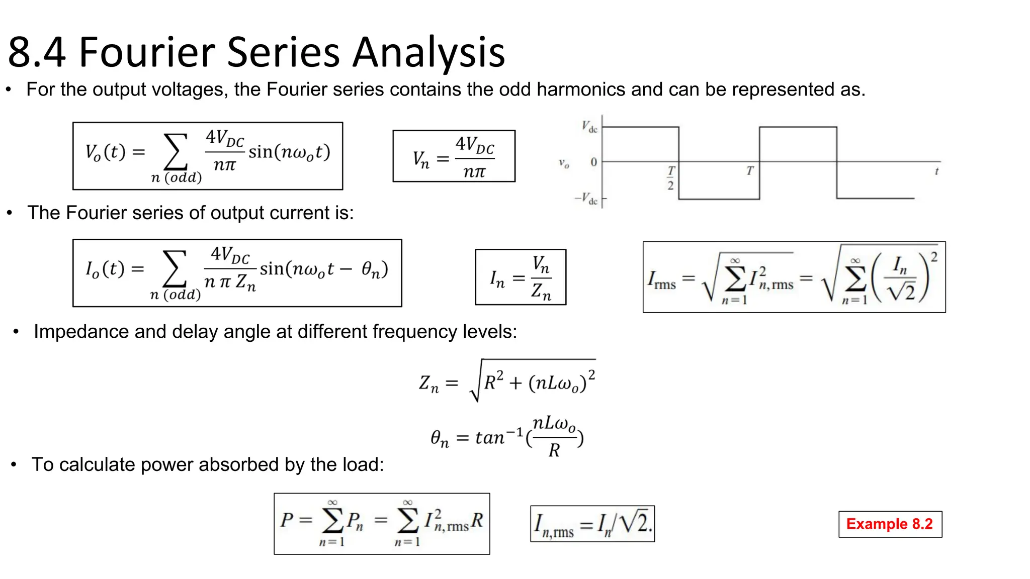
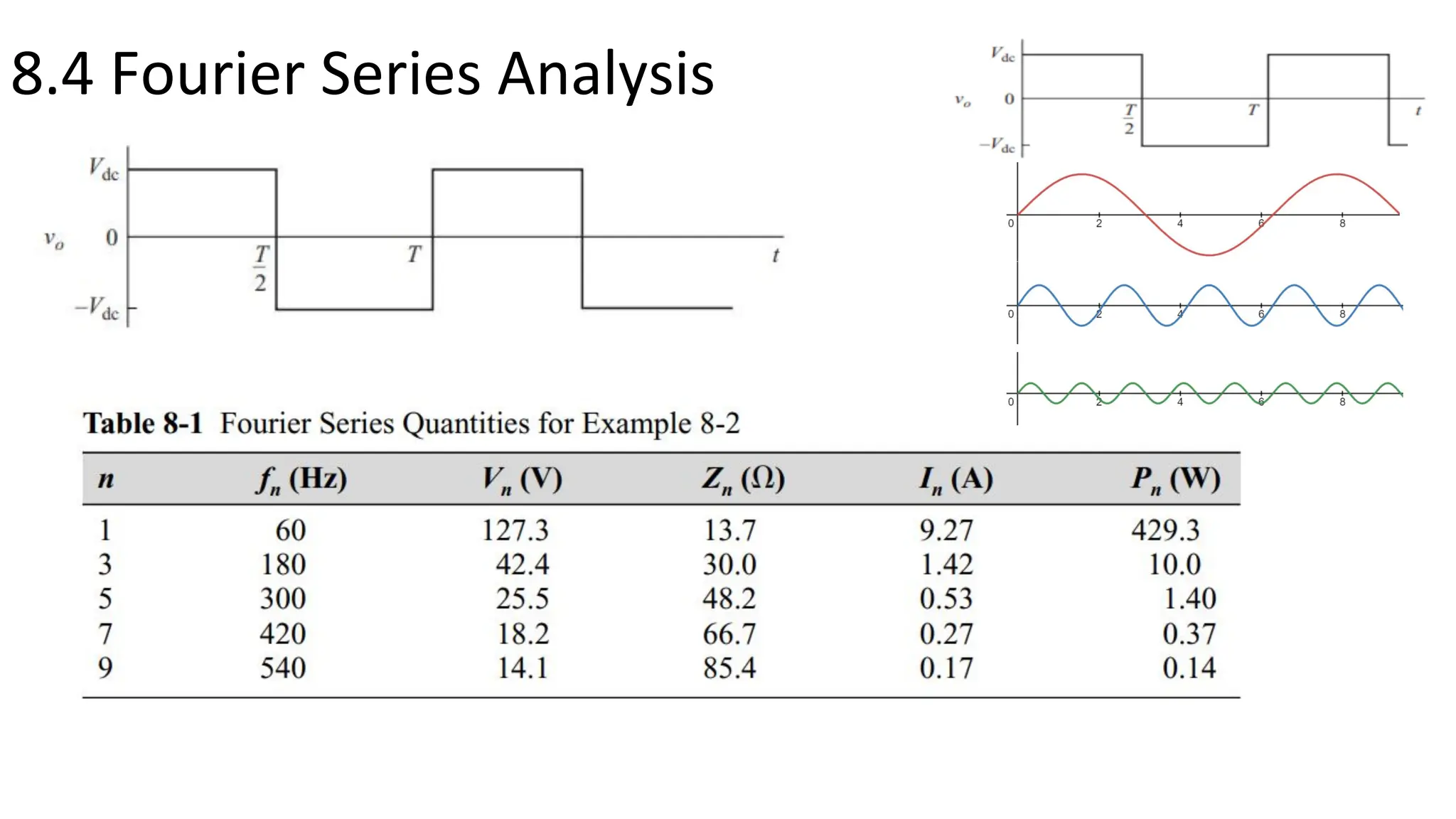
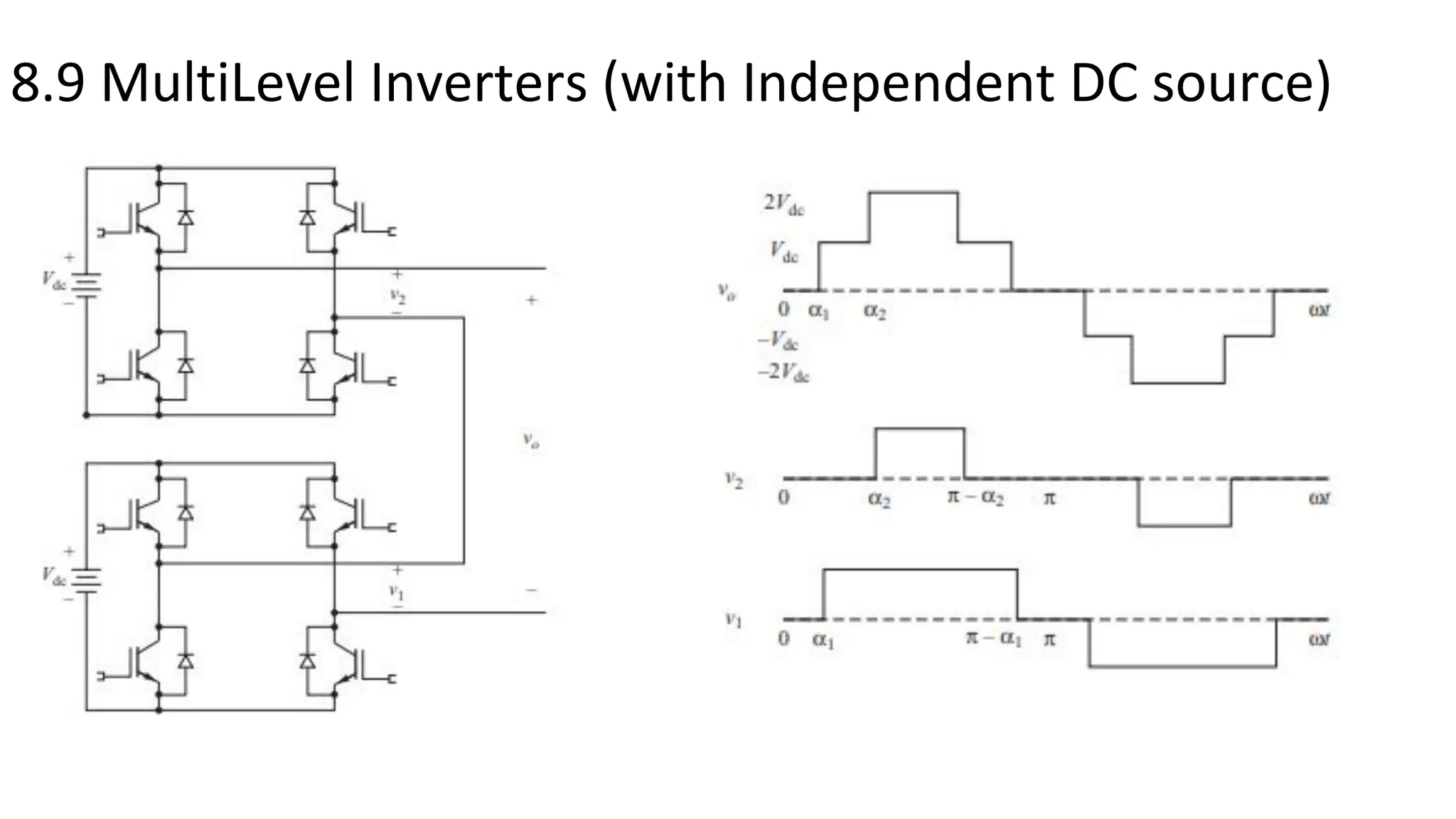
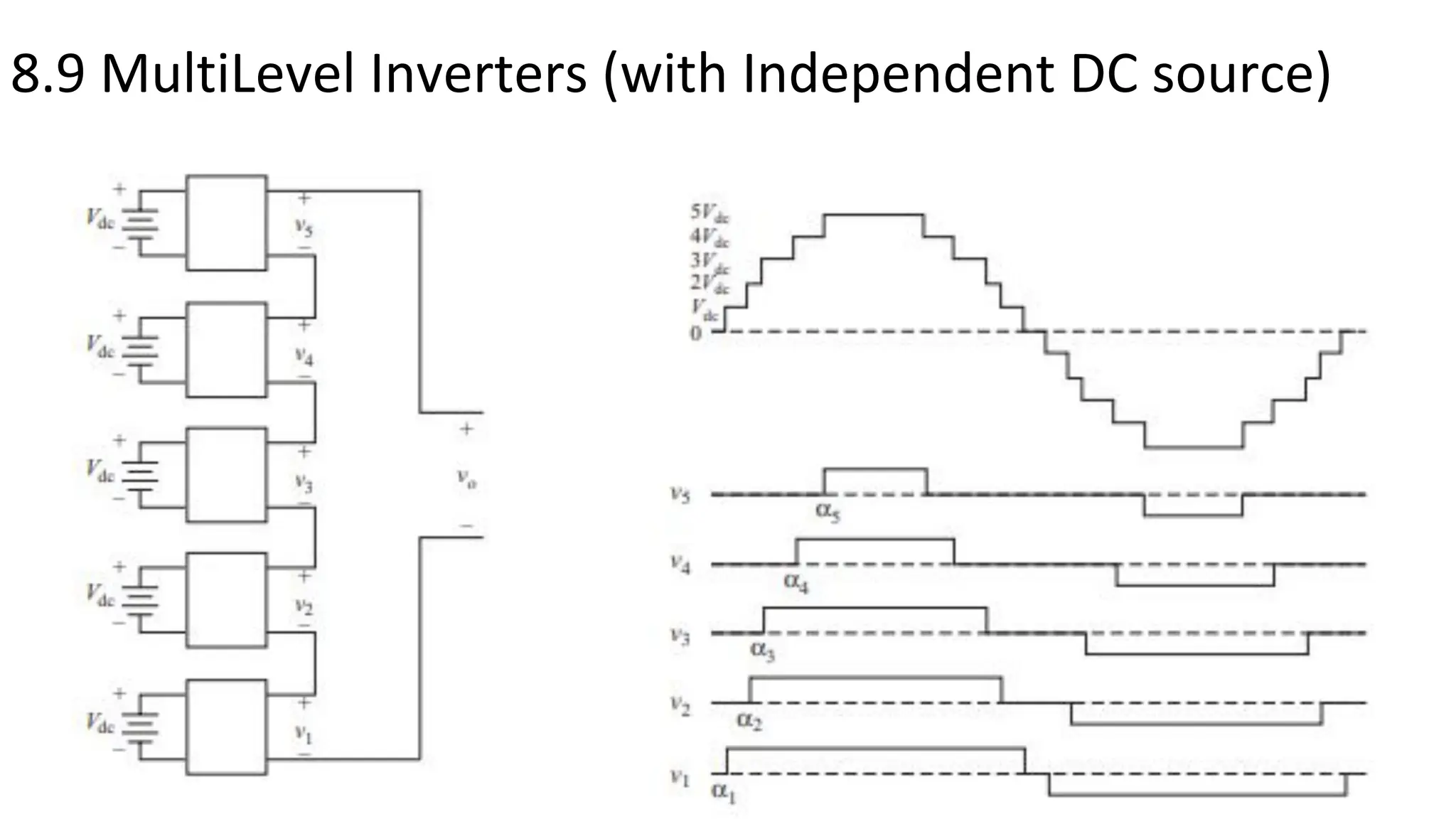
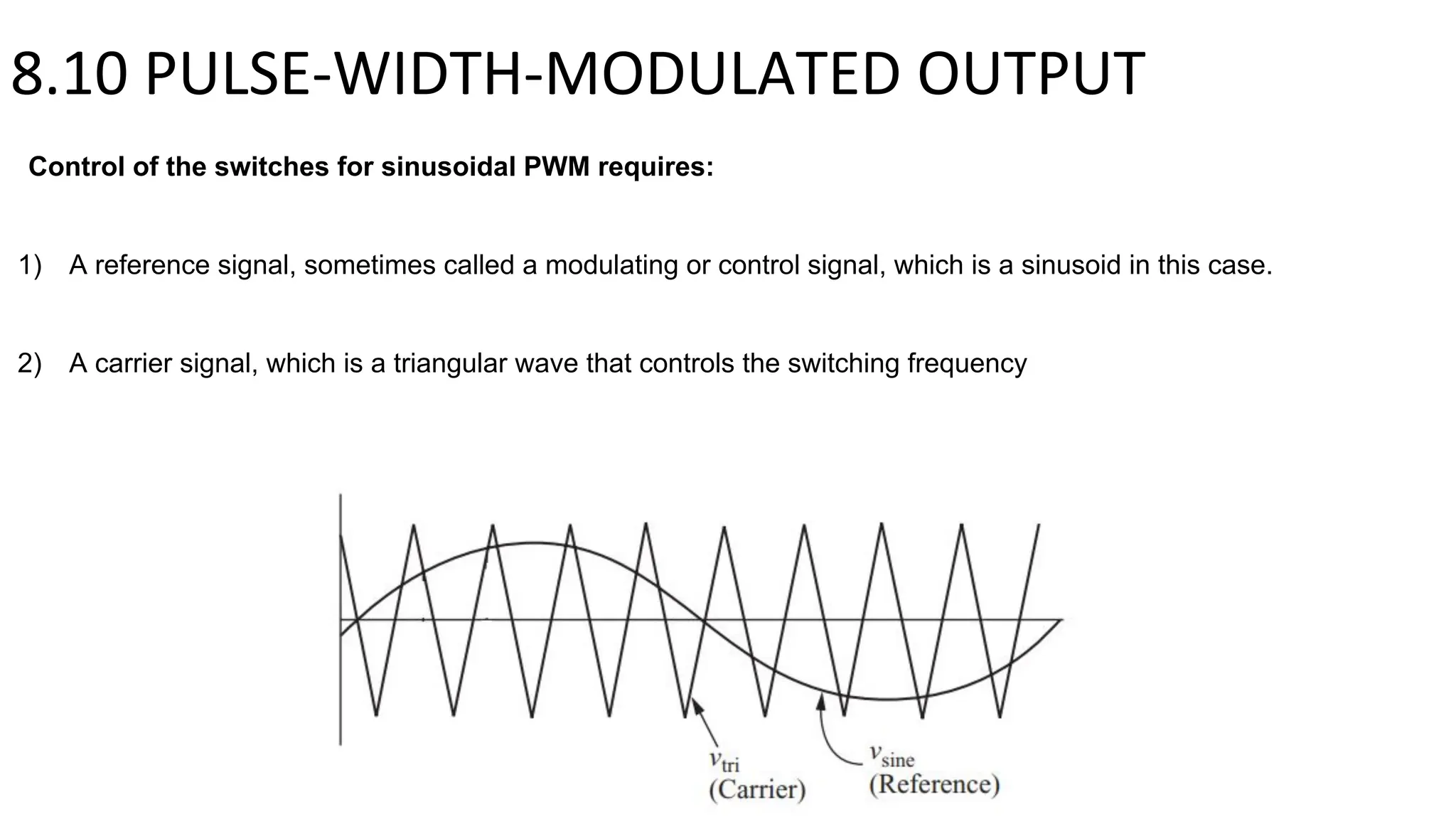
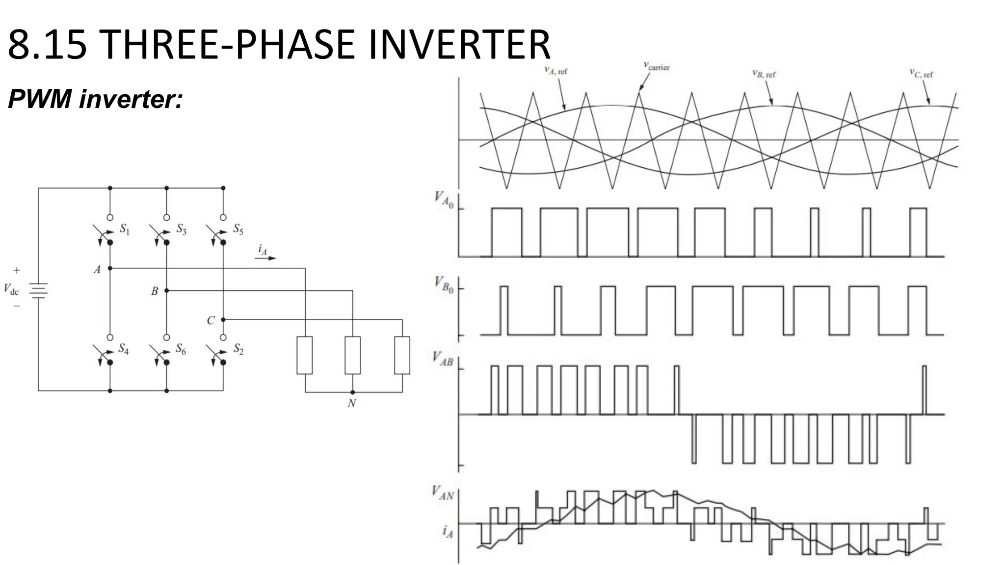

This document summarizes key points about inverters from Chapter 8: - Inverters convert DC to AC and are used in applications like AC motor drives, UPS systems, and running AC appliances from batteries. - A full-bridge converter can function as an inverter by switching DC voltage between positive, negative, and zero to produce a square wave output. PWM inverters produce a more sinusoidal output with lower harmonic distortion. - Multi-level inverters use several DC sources to produce output voltages with stepped levels, reducing harmonic distortion compared to two-level inverters. Three-phase inverters are commonly used to power three-phase loads.