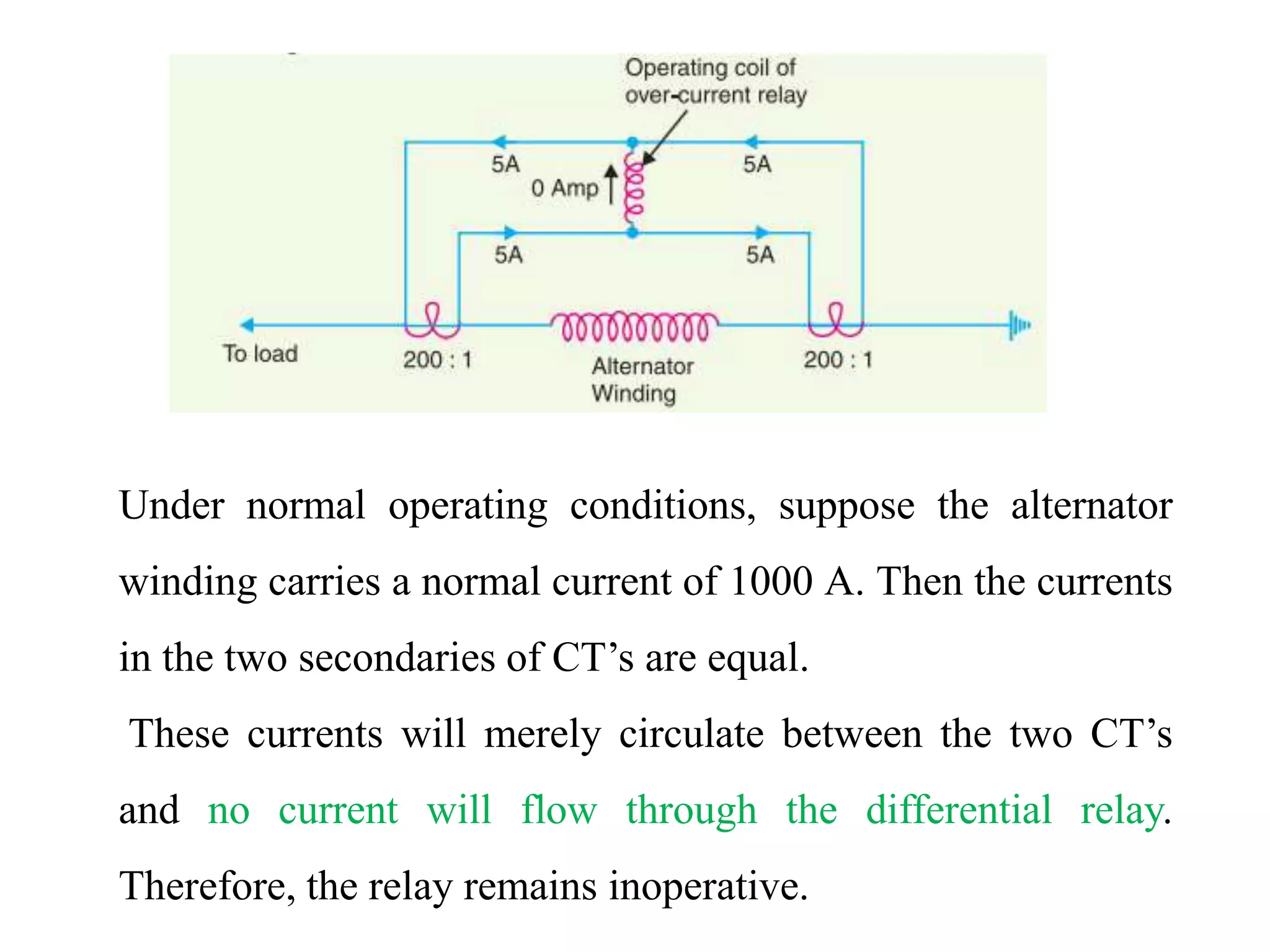
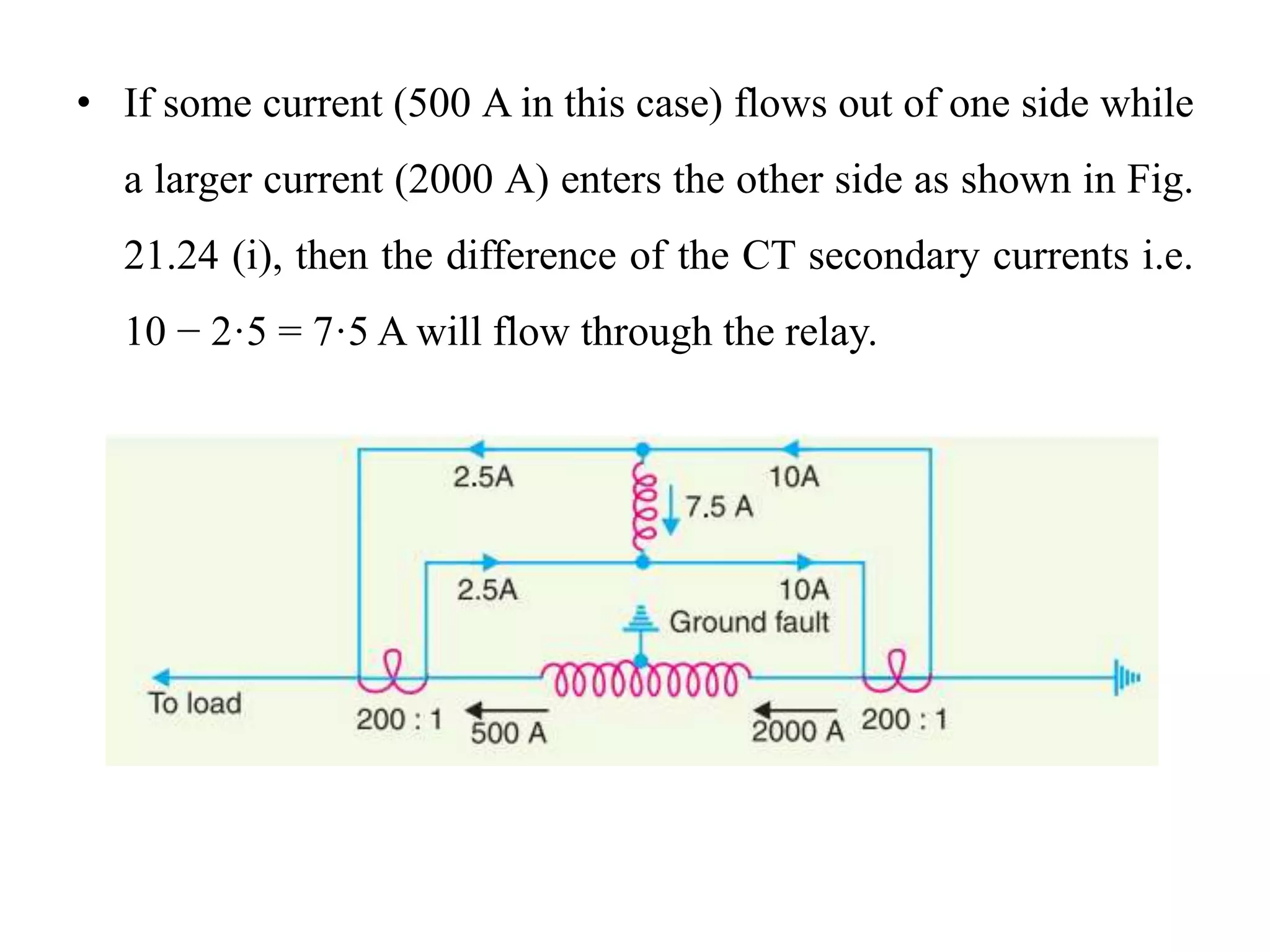
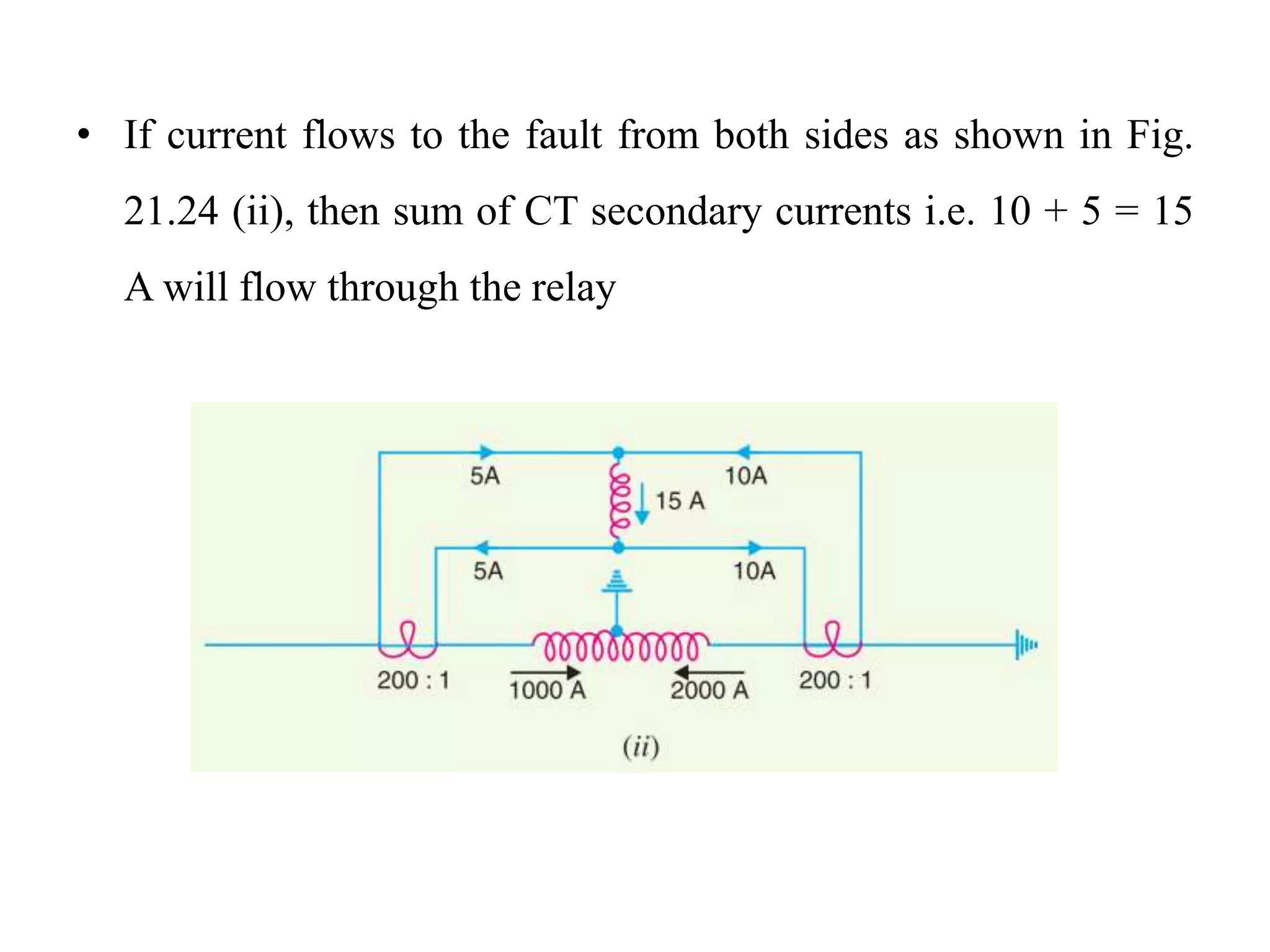
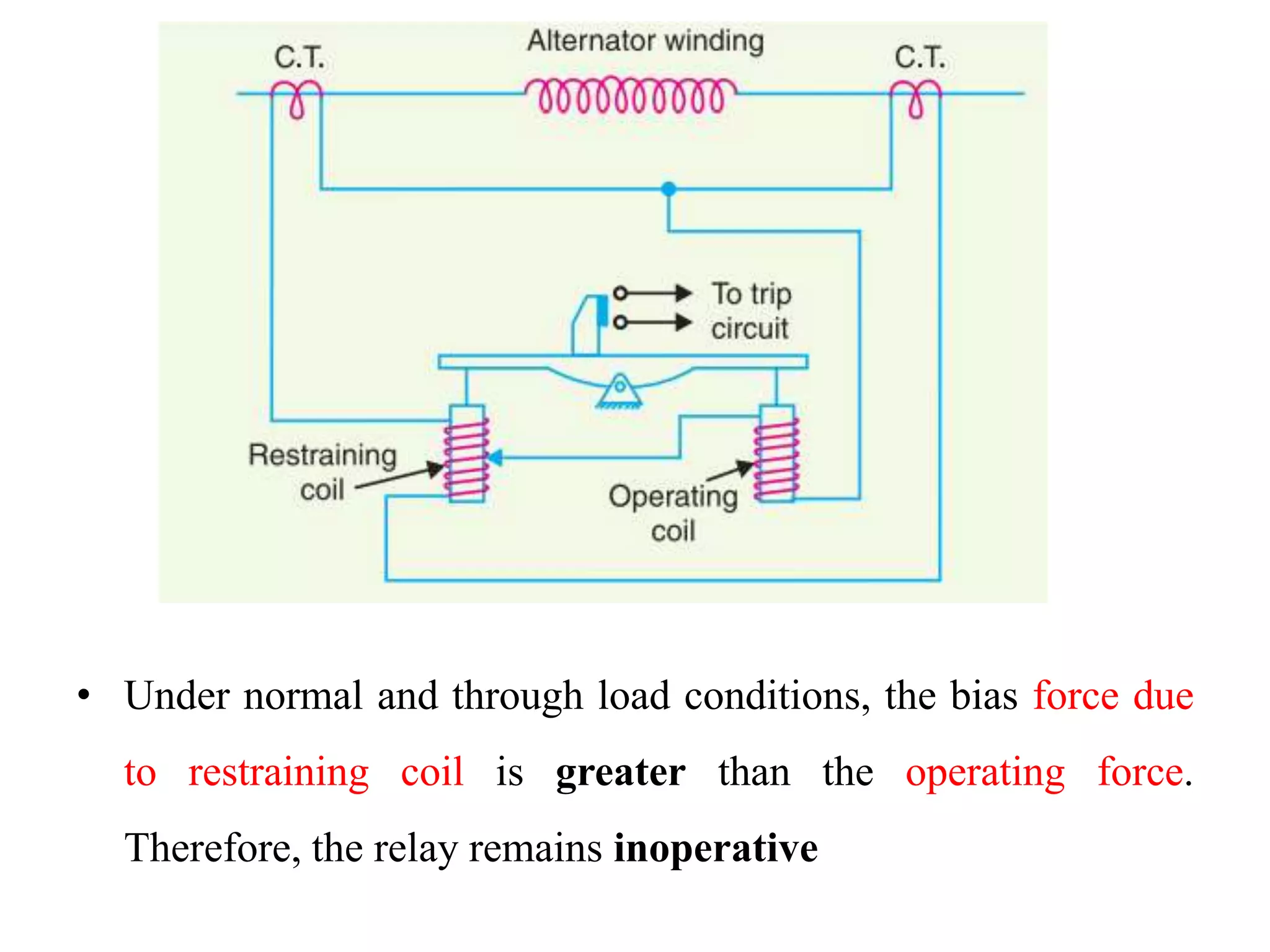
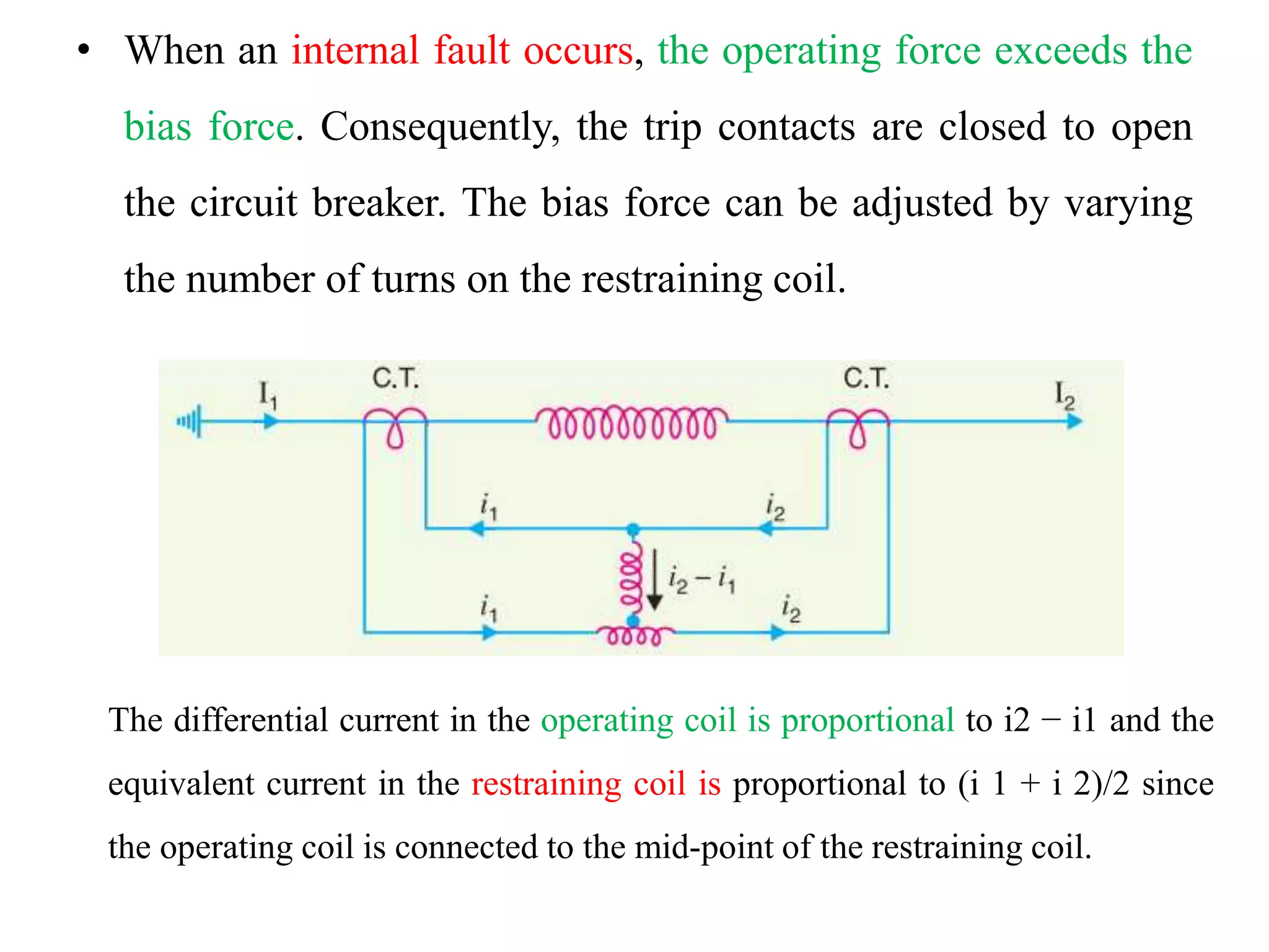
Directional relay & Differential
relay
Directional relay
• Directional element:
1. It is essentially a directional power relay which operates
when power flows in a specific direction.
2. The potential coil of this element is connected through a
potential transformer (P.T.) to the system voltage
Non-directional over current relay:
• Under normal operating conditions, power flows in the normal
direction in the circuit protected by the relay.
• Therefore, directional power relay (upper element) does not
operate, thereby keeping the overcurrent element (lower
element) un-energised.
• However, when a short-circuit occurs,
there is a tendency for the current or power to flow in the
reverse direction.
Then the disc of the upper element rotates to bridge the fixed
contacts 1 and 2. This completes the circuit for over current
element.
The disc of this element rotates and the moving contact attached
to it closes the trip circuit.
This operates the circuit breaker which isolates the faulty section.
The two relay elements are so arranged that final tripping of the
current controlled by them is not made till the following
conditions are satisfied:
 current flows in a direction such as to operate the directional
element.
 current in the reverse direction exceeds the pre-set value.
 excessive current persists for a period corresponding to the
time setting of over current element.
Differential Relay
• Most of the relays discussed so far relied on excess of current
for their operation.
• Such relays are less sensitive because they cannot make
correct distinction between heavy load conditions and minor
fault conditions.
• In order to overcome this difficulty, differential relays are
used.
A differential relay is one that operates when the phasor
difference of two or more similar electrical quantities exceeds
a pre-determined value.
• Thus a current differential relay is one that compares the
current entering a section of the system with the current
leaving the section.
• Under normal operating conditions, the two currents are equal
but as soon as a fault occurs, this condition no longer applies.
• The difference between the incoming and outgoing currents is
arranged to flow through the operating coil of the relay.
• If this differential current is equal to or greater than the pickup
value, the relay will operate and open the circuit breaker to
isolate the faulty section.
There are two fundamental systems of differential or
balanced protection
• Current balance protection
• Voltage balance protection
Current balance protection
Below Fig. shows an arrangement of an overcurrent relay
connected to operate as a differential relay.
A pair of identical current transformers are fitted on either end of
the section to be protected (alternator winding in this case).
The secondaries of CT’s are connected in series in such a way
that they carry the induced currents in the same direction.
The operating coil of the over current relay is connected across
the CT secondary circuit.
This differential relay compares the current at the two ends of the
alternator winding
Under normal operating conditions, suppose the alternator
winding carries a normal current of 1000 A. Then the currents
in the two secondaries of CT’s are equal.
These currents will merely circulate between the two CT’s
and no current will flow through the differential relay.
Therefore, the relay remains inoperative.
• If a ground fault occurs on the alternator winding as shown in
Fig. (i), the two secondary currents will not be equal and the
current flows through the operating coil of the relay, causing
the relay to operate.
• The amount of current flow through the relay will depend
upon the way the fault is being fed.
• If some current (500 A in this case) flows out of one side while
a larger current (2000 A) enters the other side as shown in Fig.
21.24 (i), then the difference of the CT secondary currents i.e.
10 − 2·5 = 7·5 A will flow through the relay.
• If current flows to the fault from both sides as shown in Fig.
21.24 (ii), then sum of CT secondary currents i.e. 10 + 5 = 15
A will flow through the relay
Disadvantages
(i) The impedance of the pilot cables generally causes a slight
difference between the currents at the two ends of the section
to be protected. If the relay is very sensitive, then the small
differential current flowing through the relay may cause it to
operate even under no fault conditions.
(ii) Pilot cable capacitance causes incorrect operation of the relay
when a large through-current flows.
(iii) Accurate matching of current transformers cannot be
achieved due to pilot circuit impedance.
Biased Beam Relay
(Percentage Differential Relay)
• The biased beam relay (also called percentage differential
relay) is designed to respond to the differential current in terms
of its fractional relation to the current flowing through the
protected section
• It is essentially an overcurrent balanced beam relay type with
an additional restraining coil. The restraining coil produces a
bias force in the opposite direction to the operating force
• Under normal and through load conditions, the bias force due
to restraining coil is greater than the operating force.
Therefore, the relay remains inoperative
• When an internal fault occurs, the operating force exceeds the
bias force. Consequently, the trip contacts are closed to open
the circuit breaker. The bias force can be adjusted by varying
the number of turns on the restraining coil.
The differential current in the operating coil is proportional to i2 − i1 and the
equivalent current in the restraining coil is proportional to (i 1 + i 2)/2 since
the operating coil is connected to the mid-point of the restraining coil.
• It is clear that greater the current flowing through the
restraining coil, the higher the value of current required in the
operating winding to trip the relay.
• Thus under a heavy load, a greater differential current through
the relay operating coil is required for operation than under
light load conditions.
• This relay is called percentage relay because the operating
current requried to trip can be expressed as a percentage of
load current.
Voltage Balance Differential Relay
• In this scheme of protection, two similar current transformers
are connected at either end of the element to be protected (e.g.
an alternator winding) by means of pilot wires.
• The secondaries of current transformers are connected in series
with a relay in such a way that under normal conditions, their
induced e.m.f.s’ are in opposition
• Under healthy conditions, equal currents (I1 = I2) flow in both
primary windings. Therefore, the secondary voltages of the
two transformers are balanced against each other and no
current will flow through the relay operating coil.
• When a fault occurs in the protected zone, the currents in the
two primaries will differ from one another (i.e. I1 ≠ I2) and
their secondary voltages will no longer be in balance.
• This voltage difference will cause a current to flow through the
operating coil of the relay which closes the trip circuit
Disadvantages
• The voltage balance system suffers from the following
drawbacks,
• (i) A multi-gap transformer construction is required to achieve
the accurate balance between current transformer pairs.
• (ii) The system is suitable for protection of cables of relatively
short lengths due to the capacitance of pilot wires.
• On long cables, the charging current may be sufficient to
operate the relay even if a perfect balance of current
transformers is attained.
The above disadvantages have been overcome in Translay
(modified) balanced voltage system.
Translay System
• This system is the modified form of voltage-balance system.
Although the principle of balanced (opposed) voltages is
retained, it differs from the above voltage-balance system in
that the balance or opposition is between voltages induced in
the secondary coils wound on the relay magnets and not
between the secondary voltages of the line current
transformers.
• Since the current transformers used with Translay scheme have
only to supply to a relay coil, they can be made of normal
design without any air gaps.
• This permits the scheme to be used for feeders of any voltage.
Constructional Details
• It consists of two identical double winding induction type relays
fitted at either end of the feeder to be protected.
• The primary circuits (11, 11a) of these relays are supplied through a
pair of current transformers.
• The secondary windings (12, 13 and 12a, 13a) of the two relays are
connected in series by pilot wires in such a way that voltages
induced in the former opposes the other.
• The compensating devices (18, 18a) neutralize the effects of pilot-
wire capacitance currents and of inherent lack of balance between
the two current transformers.
Directional relay & Differential relay.pptx

Directional relay & Differential relay.pptx

  • 1.
    Directional relay &Differential relay
  • 2.
    Directional relay • Directionalelement: 1. It is essentially a directional power relay which operates when power flows in a specific direction. 2. The potential coil of this element is connected through a potential transformer (P.T.) to the system voltage
  • 3.
    Non-directional over currentrelay: • Under normal operating conditions, power flows in the normal direction in the circuit protected by the relay. • Therefore, directional power relay (upper element) does not operate, thereby keeping the overcurrent element (lower element) un-energised.
  • 5.
    • However, whena short-circuit occurs, there is a tendency for the current or power to flow in the reverse direction. Then the disc of the upper element rotates to bridge the fixed contacts 1 and 2. This completes the circuit for over current element. The disc of this element rotates and the moving contact attached to it closes the trip circuit. This operates the circuit breaker which isolates the faulty section.
  • 6.
    The two relayelements are so arranged that final tripping of the current controlled by them is not made till the following conditions are satisfied:  current flows in a direction such as to operate the directional element.  current in the reverse direction exceeds the pre-set value.  excessive current persists for a period corresponding to the time setting of over current element.
  • 7.
    Differential Relay • Mostof the relays discussed so far relied on excess of current for their operation. • Such relays are less sensitive because they cannot make correct distinction between heavy load conditions and minor fault conditions. • In order to overcome this difficulty, differential relays are used. A differential relay is one that operates when the phasor difference of two or more similar electrical quantities exceeds a pre-determined value.
  • 8.
    • Thus acurrent differential relay is one that compares the current entering a section of the system with the current leaving the section. • Under normal operating conditions, the two currents are equal but as soon as a fault occurs, this condition no longer applies. • The difference between the incoming and outgoing currents is arranged to flow through the operating coil of the relay. • If this differential current is equal to or greater than the pickup value, the relay will operate and open the circuit breaker to isolate the faulty section.
  • 9.
    There are twofundamental systems of differential or balanced protection • Current balance protection • Voltage balance protection
  • 10.
    Current balance protection BelowFig. shows an arrangement of an overcurrent relay connected to operate as a differential relay. A pair of identical current transformers are fitted on either end of the section to be protected (alternator winding in this case). The secondaries of CT’s are connected in series in such a way that they carry the induced currents in the same direction. The operating coil of the over current relay is connected across the CT secondary circuit. This differential relay compares the current at the two ends of the alternator winding
  • 11.
    Under normal operatingconditions, suppose the alternator winding carries a normal current of 1000 A. Then the currents in the two secondaries of CT’s are equal. These currents will merely circulate between the two CT’s and no current will flow through the differential relay. Therefore, the relay remains inoperative.
  • 12.
    • If aground fault occurs on the alternator winding as shown in Fig. (i), the two secondary currents will not be equal and the current flows through the operating coil of the relay, causing the relay to operate. • The amount of current flow through the relay will depend upon the way the fault is being fed.
  • 13.
    • If somecurrent (500 A in this case) flows out of one side while a larger current (2000 A) enters the other side as shown in Fig. 21.24 (i), then the difference of the CT secondary currents i.e. 10 − 2·5 = 7·5 A will flow through the relay.
  • 14.
    • If currentflows to the fault from both sides as shown in Fig. 21.24 (ii), then sum of CT secondary currents i.e. 10 + 5 = 15 A will flow through the relay
  • 15.
    Disadvantages (i) The impedanceof the pilot cables generally causes a slight difference between the currents at the two ends of the section to be protected. If the relay is very sensitive, then the small differential current flowing through the relay may cause it to operate even under no fault conditions. (ii) Pilot cable capacitance causes incorrect operation of the relay when a large through-current flows. (iii) Accurate matching of current transformers cannot be achieved due to pilot circuit impedance.
  • 16.
    Biased Beam Relay (PercentageDifferential Relay) • The biased beam relay (also called percentage differential relay) is designed to respond to the differential current in terms of its fractional relation to the current flowing through the protected section • It is essentially an overcurrent balanced beam relay type with an additional restraining coil. The restraining coil produces a bias force in the opposite direction to the operating force
  • 17.
    • Under normaland through load conditions, the bias force due to restraining coil is greater than the operating force. Therefore, the relay remains inoperative
  • 18.
    • When aninternal fault occurs, the operating force exceeds the bias force. Consequently, the trip contacts are closed to open the circuit breaker. The bias force can be adjusted by varying the number of turns on the restraining coil. The differential current in the operating coil is proportional to i2 − i1 and the equivalent current in the restraining coil is proportional to (i 1 + i 2)/2 since the operating coil is connected to the mid-point of the restraining coil.
  • 19.
    • It isclear that greater the current flowing through the restraining coil, the higher the value of current required in the operating winding to trip the relay. • Thus under a heavy load, a greater differential current through the relay operating coil is required for operation than under light load conditions. • This relay is called percentage relay because the operating current requried to trip can be expressed as a percentage of load current.
  • 20.
    Voltage Balance DifferentialRelay • In this scheme of protection, two similar current transformers are connected at either end of the element to be protected (e.g. an alternator winding) by means of pilot wires. • The secondaries of current transformers are connected in series with a relay in such a way that under normal conditions, their induced e.m.f.s’ are in opposition • Under healthy conditions, equal currents (I1 = I2) flow in both primary windings. Therefore, the secondary voltages of the two transformers are balanced against each other and no current will flow through the relay operating coil.
  • 21.
    • When afault occurs in the protected zone, the currents in the two primaries will differ from one another (i.e. I1 ≠ I2) and their secondary voltages will no longer be in balance. • This voltage difference will cause a current to flow through the operating coil of the relay which closes the trip circuit
  • 22.
    Disadvantages • The voltagebalance system suffers from the following drawbacks, • (i) A multi-gap transformer construction is required to achieve the accurate balance between current transformer pairs. • (ii) The system is suitable for protection of cables of relatively short lengths due to the capacitance of pilot wires. • On long cables, the charging current may be sufficient to operate the relay even if a perfect balance of current transformers is attained. The above disadvantages have been overcome in Translay (modified) balanced voltage system.
  • 23.
    Translay System • Thissystem is the modified form of voltage-balance system. Although the principle of balanced (opposed) voltages is retained, it differs from the above voltage-balance system in that the balance or opposition is between voltages induced in the secondary coils wound on the relay magnets and not between the secondary voltages of the line current transformers.
  • 24.
    • Since thecurrent transformers used with Translay scheme have only to supply to a relay coil, they can be made of normal design without any air gaps. • This permits the scheme to be used for feeders of any voltage.
  • 25.
    Constructional Details • Itconsists of two identical double winding induction type relays fitted at either end of the feeder to be protected. • The primary circuits (11, 11a) of these relays are supplied through a pair of current transformers. • The secondary windings (12, 13 and 12a, 13a) of the two relays are connected in series by pilot wires in such a way that voltages induced in the former opposes the other. • The compensating devices (18, 18a) neutralize the effects of pilot- wire capacitance currents and of inherent lack of balance between the two current transformers.