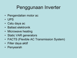
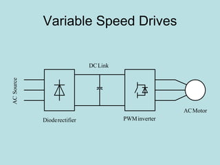
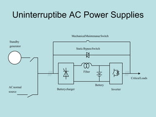
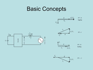
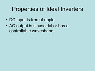
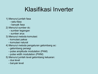
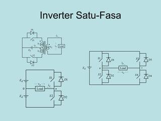
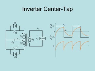
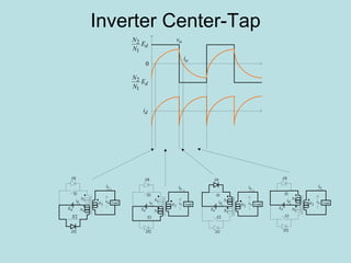
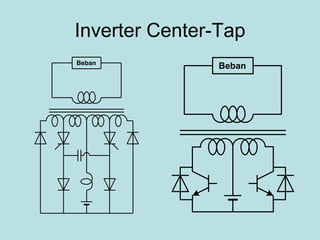
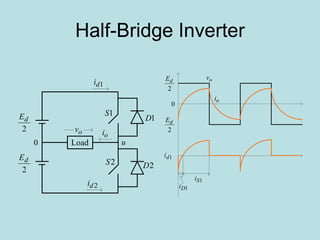
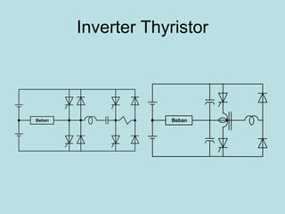
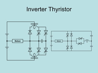
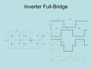
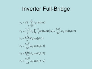
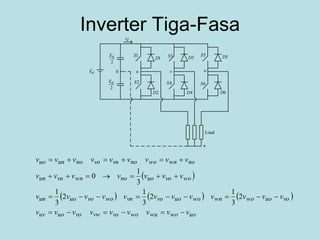
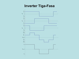
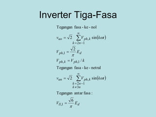
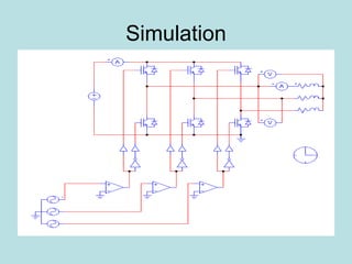
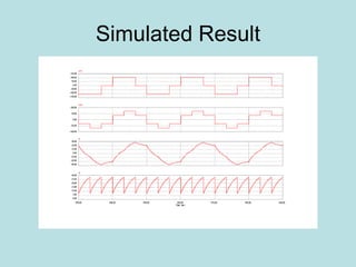
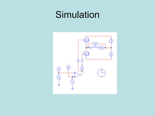
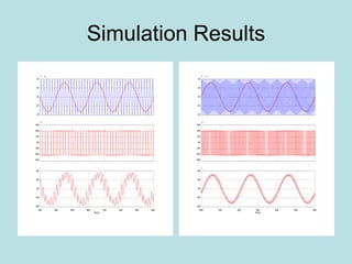
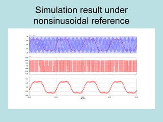
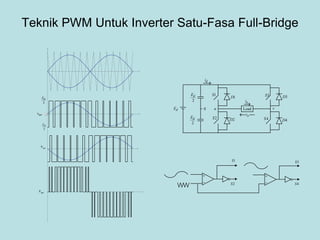
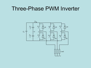
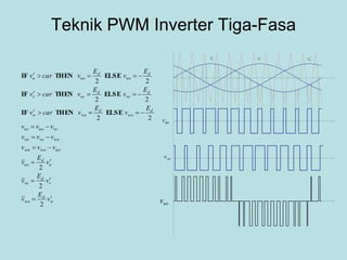
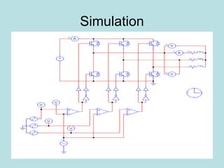
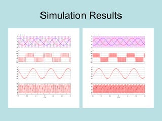
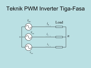
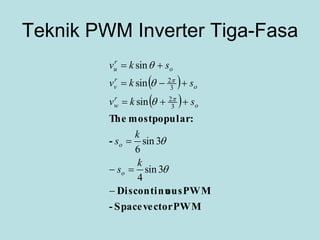
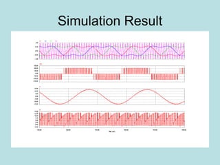
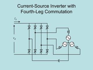
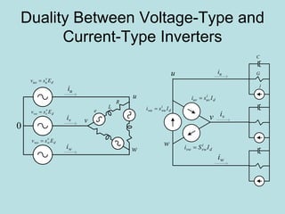
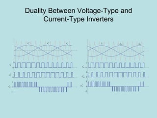
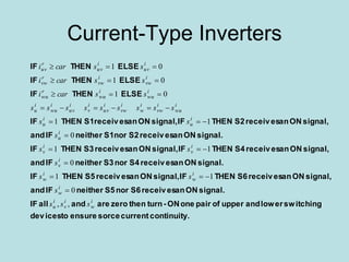
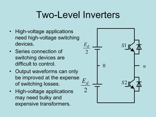
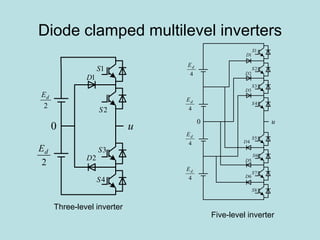
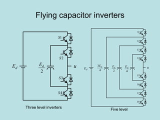
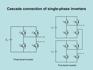
Inverter (Konverter DC – AC)
Pekik Argo Dahono
Penggunaan Inverter
• Pengendalian motor ac
• UPS
• Catu daya ac
• Ballast elektronik
• Microwave heating
• Static VAR generators
• FACTS (Flexible AC Transmission System)
• Filter daya aktif
• Penyearah
Variable Speed Drives
SourceAC
rectifierDiode inverterPWM
LinkDC
MotorAC
Uninterruptibe AC Power Supplies
chargerBattery
Bettery
Inverter
Filter
SwitchBypassStatic
SwitcheMaintenancMechanical
LoadsCritical
source
normalAC
generator
Standby
Basic Concepts
oV E
L
oI
dE
dI
Inverter
oV
Lo XjI
E
E
E
Lo XjI
Lo XjI
oV
oV
E Lo XjI
oV
lagging
0PF
1PF
leading
0PF
1PF
oI
oI
oI
oI
Properties of Ideal Inverters
• DC input is free of ripple
• AC output is sinusoidal or has a
controllable waveshape
Klasifikasi Inverter
1) Menurut jumlah fasa
- satu-fasa
- banyak fasa
2) Menurut sumber dc:
- sumber tegangan
- sumber arus
3) Menurut metoda komutasi:
- komutasi paksa
- komutasi natural
4) Menurut metoda pengaturan gelombang ac:
- gelombang persegi
- pulse amplitude modulation (PAM)
- pulse width modulation (PWM)
5) Menurut jumlah level gelombang keluaran:
- dua level
- banyak level
Inverter Satu-Fasa
dE


1S
1D
2S
2D
ov Load
oi
1N
1N
2N
di
dE
1S
1D
2S 2D
dE
Load u0
ov
oi
dE
1S
1D
2S 2D
Load
3S 3D
4S 4D
u v
ov
oi
Inverter Center-Tap
dE


1S
1D
2S
2D
ov Load
oi
1N
1N
2N
di
dE
N
N
1
2
dE
N
N
1
2
0
ov
oi
di
Inverter Center-Tap
dE
N
N
1
2
dE
N
N
1
2
0
ov
oi
di
dE


1S
1D
2S
2D
ov Load
oi
1N
1N
2Ndi
dE


1S
1D
2S
2D
ov Load
oi
1N
1N
2Ndi
dE


1S
1D
2S
2D
ov Load
oi
1N
1N
2Ndi
dE


1S
1D
2S
2D
ov Load
oi
1N
1N
2Ndi
Inverter Center-Tap
BebanBeban
Analisis Tegangan Output
Inverter Center-Tap
 
   
kVV
E
N
N
tdtE
N
N
V
tkVv
k
dd
nk
k
/
22
sin
22
sin2
:Tegangan
1
1
22/
0
1
2
1
12












Inverter Center-Tap
• Sederhana
• Komponen minimum
• Harus pakai trafo
• Cocok untuk daya rendah (< 1 kW)
• Cocok untuk tegangan dc yang rendah
• Pengaturan tegangan dilakukan dengan
menggunakan trafo ferroresonance.
Half-Bridge Inverter
1S
1D
2S 2D
2
dE
Load u0
ov
oi
2
dE
1di
2di
2
dE
0
ov
oi
2
dE
1Si
1Di
1di
Analisis Tegangan Output
Inverter Half-Bridge
 
   
kVV
Etdt
E
V
tkVv
k
d
d
nk
ko
/
2
sin
2
sin2
:Tegangan
1
2/
01
12












Inverter Thyristor
Beban Beban
Inverter Thyristor
Beban Beban
Inverter Full-Bridge
2
dE
2
dE
0
2
dE
2
dE
0
0
dE
dE
uov
vov
uvv
uvi

1S 2S
4S 3S 4S
di
1S
1D
2S 2D
Load
3S 3D
4S 4D
u v
ov
oi
dE
2
dE
2
dE
0
di
Inverter Full-Bridge
 
     
 
 
 
 2/7cos
7
22
2/5cos
5
22
2/3cos
3
22
2/cos
22
2/cos
22
sin
22
sin2
7
5
3
1
2/
2/
12















d
d
d
d
ddk
nk
ko
EV
EV
EV
EV
kE
k
tdtkEV
tkVv










Inverter Tiga-Fasa
 
     
uowowuwovovwvououv
vouowownwouovovnwovououn
wovouonownvnun
nownwonovnvonounuo
vvvvvvvvv
vvvvvvvvvvvv
vvvvvvv
vvvvvvvvv




2
3
1
2
3
1
2
3
1
3
1
0
1S
1D
2S
2D
udE
2
dE
2
dE
0
di
3S 3D
4S
4D
v
5S 5D
6S
6D
w
n
Load
Inverter Tiga-Fasa
2
dE
2
dE
0
0
0
0
0
2
dE
2
dE
2
dE
2
dE
3
2 dE
3
dE
3
dE
3
2 dE
dE
dE
uov
vov
wov
unv
uvv
Inverter Tiga-Fasa
 
 
dll
nk
nk
kphun
phkph
dph
nk
kphuo
EV
tkVv
kVV
EV
tkVv




6
:fasaantarTegangan
sin2
netral-ke-fasaTegangan
/
2
sin2
nol-ke-fasaTegangan
1,
3
12
,
1,,
1,
12
,












Simulation
Simulated Result
Teknik PWM
1. Sampling Based PWM:
• Natural sampling (Carrier Based)
• Regular sampling
2. Programmed PWM:
• Eliminated Harmonics
• Minimum Harmonics
Teknik PWM
1S
2
dE
Load0
ov
oi
2
dE
1di
2di
1D
2S
2D
u


o 2
dE
0
2
dE
uov
If fc/fr integer, the technique is called synchronous otherwise asynchronous
Regular Sampling
2
dE
0
2
dE
uov
Simulation
Simulation Results
Analisis Tegangan Keluaran nverter PWM Satu-Fasa
 
 
       
 
   












 





1
0
1
cossinsin
2
sin
2
sin
sin
2
coscos
cos
./
22
12
2
n
s
dd
o
r
d
n
ssss
d
n
n
snoo
sON
r
ddd
s
OFFON
o
tnkn
k
EE
kv
kv
n
n
E
C
tdtntdtn
E
C
tnCvv
TT
v
EEE
T
TT
v














makaJika
:FourierDeret
manayang
:teganganrata-rataNilai
0
0
2
dE
2
dE

rv
car
ONT
sT
Simulation result under
nonsinusoidal reference
Analisis Tegangan keluaran
• Maximum peak output voltage is Ed/2. This
value is less than the fundamental
component of square-wave output voltage.
• The output current waveform is almost
sinusoidal when the switching frequency is
high.
• Because the switching frequency is high,
the switching losses are also high.
Analisis Riak
0
2
dE

2
dE
r
uv
carrier
ot 1t 2t 3t 4t
sT
1ToT oT
ui
~
uv
 
 
 
 






























434
311
1
for
for2
for
1~
Thus,
~
~~
2
1
2
2
Then
~
and~assumeusLet
:equationtageOutput vol
ttttt
L
v
ttttt
L
v
E
T
L
v
ttttt
L
v
dtvv
L
i
dt
id
LiRvvv
e
dt
id
LiR
E
T
TE
vv
iiivvv
e
dt
di
LRiv
uo
uo
d
o
uo
oo
uo
uouou
u
uuououo
u
u
u
d
s
ONd
ruo
uuuuououo
u
u
uuo
Analisis Riak












2
0
2
,
22
1
~
2
1~
~1~
sin
2
1
2
1
2
1
2
12
dII
dti
T
I
kv
v
T
T
v
T
T
uavu
Tt
t u
s
u
r
u
r
s
r
u
s
o
so
o
:rippleofvalueRMS
:rippleofvaluesquareMean
Programmed PWM
ganjil.Untukn
n
n
E
b
n
n
E
a
M
k
k
kd
n
M
k
k
kd
n


















2
1
2
1
sin)1(
2
cos)1(1
2




Teknik PWM Untuk Inverter Satu-Fasa Full-Bridge
2
dE
2
dE
uov
vov
uvv
1S
1D
2S 2D
Load
3S 3D
4S 4D
u v
ov
oi
dE
2
dE
2
dE
0
di


o


o
1S
2S
3S
4S
Three-Phase PWM Inverter
1S
1D
2S
2D
udE
2
dE
2
dE
0
di
3S 3D
4S
4D
v
5S 5D
6S
6D
w
n
Load
Teknik PWM Inverter Tiga-Fasa
r
uv r
vv r
wv
uov
vov
uvv
r
w
d
wo
r
v
d
vo
r
u
d
uo
uowowu
wovovw
vououv
d
wo
d
wo
r
w
d
vo
d
vo
r
v
d
uo
d
uo
r
u
v
E
v
v
E
v
v
E
v
vvv
vvv
vvv
E
v
E
vcarv
E
v
E
vcarv
E
v
E
vcarv
2
2
2
22
22
22









ELSETHENIF
ELSETHENIF
ELSETHENIF
Simulation
Simulation Results
Teknik PWM Inverter Tiga-Fasa
n
Load
0
uov
vov
wov
wi
vi
ui
Teknik PWM Inverter Tiga-Fasa
 
 
PWMvectorSpace-
PWMousDiscontinu
-
:popularmostThe













3sin
4
3sin
6
sin
sin
sin
3
2
3
2
k
s
k
s
skv
skv
skv
o
o
o
r
w
o
r
v
o
r
u
Simulation Result
Switching Function Concept
 
 
 
functionswitchingphase-to-phaseis
ELSETHENIF
ELSETHENIF
ELSETHENIF
otherwisethen
signalONanreceivesdeviceswitchinguppertheIF
uv
dwuduwuGwGwu
dvwdwvwGvGvw
duvdvuvGuGuv
dwwGdvvGduuG
ww
r
w
vv
r
v
uu
r
u
s
EsEssvvv
EsEssvvv
EsEssvvv
EsvEsvEsv
sscarv
sscarv
sscarv
ss








01
01
01
.01
Current-Type Inverters
R L e
C
1S
u
2S
3S
v
4S 6S
w
5S
dI
0
u
1S
2S
u
v
w
R
L
e
3S
v
4S
5S
6S
w
dE
Current-Type Inverter
Voltage-Type Inverter
Autosequential Commutation
Current-Source Inverters
Motor
Induction
dI
dv
Current-Source Inverter with
Individual Commutation
dI
dv
Bridge
Auxiliary
Bridge
Main
Motor
Induction
Current-Source Inverter with
Fourth-Leg Commutation
dI
dv
Duality Between Voltage-Type and
Current-Type Inverters
0
d
v
uuo Esv 
d
v
vvo Esv 
d
v
wwo Esv 
ui
vi
wi
u
v
w
R
L
e
u
v
w
C
G
j
d
i
uvuv Isi 
d
i
vwvw ISi 
d
i
wuwu Isi 
ui
vi
wi
Duality Between Voltage-Type and
Current-Type Inverters
r
uvi r
vwi r
wui
0
1
i
uvs
0
1
1
i
vs
i
vws 0
1
r
uv r
vv r
wv
0
1
v
us
0
1
1
v
uvs
v
vs
0
1
Current-Type Inverters
.continuitycurrentsorceensuretodevices
switchinglowerandupperofpaironeON-turnthenzeroareandallIF
signal.ONanreceivesS6norS5neitherIFand
signal,ONanreceivesS6THENIFsignal,ONanreceivesS5THENIF
signal.ONanreceivesS4norS3neitherIFand
signal,ONanreceivesS4THENIFsignal,ONanreceivesS3THENIF
signal.ONanreceivesS2norS1neitherIFand
signal,ONanreceivesS2THENIFsignal,ONanreceivesS1THENIF
ELSETHENIF
ELSETHENIF
ELSETHENIF
i
w
i
v
i
u
i
w
i
w
i
w
i
v
i
v
i
v
i
u
i
u
i
u
i
wu
i
vw
i
w
i
vw
i
uv
i
v
i
uv
i
wu
i
u
i
wu
i
wu
r
wu
i
vw
i
vw
r
vw
i
uv
i
uv
r
uv
sss
s
ss
s
ss
s
ss
sssssssss
sscari
sscari
sscari
,,
0
11
0
11
0
11
01
01
01










Current-Type Inverters
• At present, voltage-type inverters are more popular than
current-type inverters.
• Current-type inverters are commonly used as PWM
rectifiers.
• Advances on superconductor will increase the use of
current-type inverters.
• At present, several manufacturers introduce reverse-
blocking devices on one module.
• Current-type inverters are introduced for medium voltage
ac drives because the input and output currents are
almost sinusoidal, inherently four-quadrants, and short-
circuit proof.
Space-Vector PWM
 
3/2
2
3
2
j
coboaoo
ea
avvavv



:definitionvectorVoltage
100011
101001
010 110
111000
Space Vector PWM
 
 
21
1
2
2
21
2
2
1
1
21
sincos3
2
3
sin
3
3
3
3
sin
3
1
3
2
cos
ttTt
E
V
Tt
E
V
Tt
E
T
t
V
E
T
t
E
T
t
V
v
T
t
v
T
t
v
T
t
v
vbvaVev
so
d
s
d
s
d
s
d
s
d
s
zero
s
o
ss
r
o
jr
o














dEv
3
2
1 

3/
2
3
2 j
deEv 

r
ov


Space Vector PWM
aphase
bphase
cphase
2
ot
1t 2t 2
ot
0
0
0
Two-Level Inverters
• High-voltage applications
need high-voltage switching
devices.
• Series connection of
switching devices are
difficult to control.
• Output waveforms can only
be improved at the expense
of switching losses.
• High-voltage applications
may need bulky and
expensive transformers.
2
dE
2
dE
u0
1S
2S
Diode clamped multilevel inverters
2
dE
2
dE
u0
1S
2S
1D
2D
3S
4S
0
1D
u
1S
2S
3S
4S
4
dE
2D
3D
4D
5D
6D
5S
6S
7S
8S
4
dE
4
dE
4
dE
Three-level inverter
Five-level inverter
Flying capacitor inverters
2
dE u
1S
2S
3S
4S
dE
Three level inverters Five level
2
dE u
1S
2S
3S
4S
dE
4
3 dE
4
dE
5S
6S
7S
8S
Cascade connection of single-phase inverters
u
1S
2S
v
3S
4S
dE
1S
2S
v
3S
4S
dE
u
1S
2S
3S
4S
dE
Three level inverter
Five level inverter

Inverter