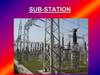
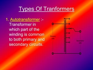
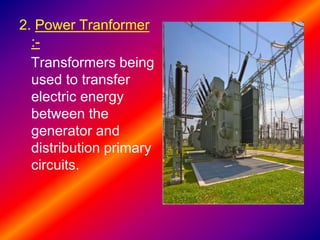
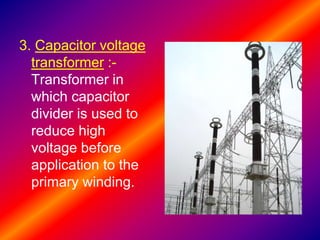
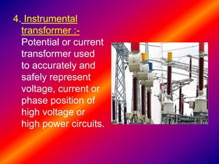
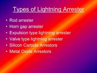
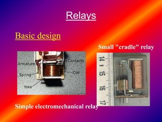
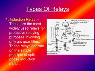
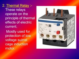
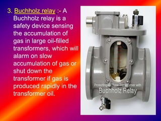
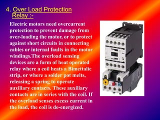
This document provides information about a 132/33 kv sub-station, including a single line diagram and descriptions of its main components. It discusses the transformer, types of transformers, lightning arresters, relays, circuit breakers and their operating principles. The transformer uses electromagnetic induction to transfer energy between coils. Lightning arresters protect equipment from surges, while relays and circuit breakers detect faults and interrupt current flow to protect circuits.
Presentation on 132/33 KVSubstation Training Sakshi Rastogi
This is a presentation based on the 132/33 KV substation. At which I have done my vocational Training. this presentation uncovers all the aspects related to the substation.
This presentation discusses the key protection devices used in electrical substations. It introduces current transformers and potential transformers, which reduce current and voltage levels for protection relays. Relays detect faults by measuring currents and voltages. When a fault is detected, relays signal circuit breakers to isolate the faulty component. Other protection devices discussed include lightning arresters, isolators, and surge diverters. The objective of the substation protection system is to isolate only faulty parts of the network while keeping the rest operational.
A substation is a high-voltage electric facility used to switch generators, equipment, and circuits in and out of a system. It also changes AC voltages and converts between AC and DC. Substations can be classified by their service, mounting, function, type of apparatus, and control. They include transformers, switches, circuit breakers, and other equipment to distribute power at appropriate voltages for transmission and utilization.
Report on industrial summer training on 220 kv substationAshutosh Srivastava
The document is a report submitted by Ashutosh Srivastava detailing his 6-week summer training at the 220/132 kV substation in Barahuwa, Gorakhpur, Uttar Pradesh, India. It includes sections on the equipment found at a typical 220kV substation such as busbars, isolators, circuit breakers, transformers, and instrument transformers. It also discusses the selection of suitable substation sites and provides an overview of Uttar Pradesh Power Corporation Limited, the organization responsible for electricity transmission and distribution in Uttar Pradesh.
This document provides an overview of the key components of a 132kV substation, including: circuit breakers, protective relays, lightning arresters, bus bars, switches, the control room, transformers, power line carrier communication (PLCC), and remote terminal units (RTU). It describes the basic functions of these components in powering homes and businesses safely and efficiently.
The document describes the 132KV Bharwa Sumerpur substation of the Uttar Pradesh Power Transmission Corporation Limited (UPPTCL). It provides an overview of UPPTCL and discusses the key components of the substation, including transformers, lightning arrestors, circuit breakers, isolators, and relays. Diagrams of the substation's single line diagram and components like circuit breakers are presented to explain their functions in electricity transmission and protection.
The document provides information about Tejveer Choudhary's industrial training at the 132 kV Bissau substation operated by RVPNL. It includes an acknowledgement expressing gratitude to the assistant engineer, Mr. Dilip Singh, for his guidance during the training. The document then covers various topics related to substation design and components, including earthing and bonding, transformer types, circuit breakers, protective relays, busbars, and other equipment.
The document discusses various components used in electrical substations. It describes key equipment like transformers, circuit breakers, isolators, busbars, instrument transformers, and protection devices. It also discusses the purpose of a substation to step up or down voltages for transmission or distribution and provide protection for the transmission system. The control room is mentioned as the place from where all substation equipment is monitored and controlled.
The document is a report summarizing Shuvam Pathania's industrial training at the 220/132/33 KV Grid Sub Station in Jassure. It includes an acknowledgements section thanking those who contributed, a certificate of completion, and a contents listing the topics covered in the report such as the functions of a substation, elements of a substation like circuit breakers and transformers, and an overview of the Jassure Substation.
This document is an industrial training report submitted by Swapnil Kumar Gupta for their Bachelor of Technology degree in Electrical Engineering. The report provides an overview of Swapnil's 2-week industrial training at the 220kV substation in Rewa Road, Allahabad, which is operated by Uttar Pradesh Power Transmission Corporation Limited. The report includes details about the equipment and processes at the substation, as well as declarations, acknowledgements, and chapters covering topics like the selection of substation sites, common equipment used in 220kV substations, and descriptions of the transformer and other components.
This document provides an overview of a presentation on a summer training at a 132/33 kV sub-station in Allahabad, India. It discusses key equipment used in sub-stations including transformers, protection devices like Buchholz relays and silica gel breathers, cooling equipment, and other critical infrastructure like circuit breakers, capacitor banks, potential and current transformers, isolators, and insulators. It also describes the functions of this equipment and why they are important components of the power distribution system.
The document provides information from a presentation on a summer training conducted at a 33/11 kV substation in Basti, Uttar Pradesh, India. It defines a substation and describes its key components like transformers, buses, protective devices like circuit breakers and relays. It explains the working of these components and equipment located at substations. The document also discusses the main parts of a transformer and testing conducted on transformers.
The document is a presentation on the Liluah 132/33/25 KV substation in West Bengal. It includes acknowledgments, a single line diagram of the substation, and sections covering various equipment found at the substation like electrical busbars, protective relay schemes, lightning protection, isolators, capacitor banks, powerline carrier communication, batteries, earth transformers, traction transformers, station service transformers, and power transformers. Technical specifications are provided for some of the major equipment.
The document provides an overview of the 33/11kV Phidim substation located in Phidim, Panchthar district, Nepal. It was established in 2058 BS by Nepal Electricity Authority. The substation steps down electricity from the national 33kV grid to 11kV to supply power to local areas. It is responsible for controlling energy exchange, load shedding, fault analysis and improving the transmission system. The substation layout, single line diagram, and organizational structure are presented. Key equipment used includes transformers, circuit breakers, isolators, lightning arrestors, and insulators.
This document provides an overview of a 220/132 kV substation in Barahuwa, India. It includes a single line diagram showing the incoming and outgoing sections. The substation has three main parts: a panel section containing control and relay panels, a yard section with 220 kV, 132 kV and 33 kV sections, and a battery room powering the station. It describes the various components used in the substation like transformers, circuit breakers, isolators etc. The training program helped broaden the author's knowledge of power transmission and distribution.
Presentation on 132/33KV BSPTCL(Bodhgaya Substation)Rahul Prajapati
The document provides information about the 132/33kV Bodhgaya substation in Bihar, India. It discusses key components of the substation including three transformers ranging from 50-160 MVA, lightning arrestors, current and potential transformers, circuit breakers using oil, air, SF6 and vacuum technologies, isolators, capacitor banks, fuses, and bus couplers connecting generators and feeders to main and spare bus bars. The substation is part of the transmission network operated by Bihar State Power Transmission Company Limited.
PPT ON SUMMER TRAINING FROM UPPCL 132/33 KV SUB STATIONSwatantra SwAt
The document discusses the key components and operations of a 132/33kV grid substation located in Allahabad, India. It provides details on the location, equipment capacities, transformer types, protection devices, and sequencing of components for incoming and outgoing feeders. The substation aims to safely transform and distribute electricity to consumers while protecting equipment from faults using devices like circuit breakers, relays, and earthing systems. Practical experience at the substation enhanced the trainee's theoretical understanding of power transmission and distribution.
Training report-in-a-132-k-v-substationankesh kumar
This document provides a training report for a summer internship at the Uttar Pradesh Power Corporation Limited 132/33 kV substation in Chandauli, Barabanki, India.
The report includes an introduction to the Uttar Pradesh Power Corporation and the purpose of the internship. It also provides a preface describing the learning experience and thanks to those involved.
The report then gives an acknowledgement and thanks to those who guided the internship. It provides a rough description of the Chandauli, Barabanki substation including incoming and outgoing voltages and feeders. It also includes definitions and descriptions of substations and the equipment within them.
A brief about 33kv Substation........
like and share.................
want some help in your ppt or in any project visit..
https://www.fiverr.com/dawachya
The document describes the 132kV Vaishali substation of the Uttar Pradesh Power Transmission Corporation Limited. It discusses the key components of the substation including transformers, circuit breakers, isolators, capacitor banks, relays, and more. The substation receives power from two incoming 132kV lines and distributes it to various outgoing 33kV feeders serving the local area. Diagrams are provided to illustrate the layout and components that make up the substation.
This document is a certificate from the JKPDD substation in Wanpoh, Anantnag certifying that Sheikh Shakir Zahoor underwent project training there from June 26th to August 14th, 2014. It provides an overview of his training at the 132/33kV substation where incoming power at 132kV is stepped down to 33kV before being distributed. The document also includes an acknowledgment from Sheikh Shakir thanking those involved in his training and an introduction describing the components and functions of electrical substations.
Components of an electrical sub-station and their functions.
i.e. What are the basic components of an electrical sub station or a grid station and how they contribute in supplying, transformation and transmitting power?
The document discusses types of substations. There are several types including transmission substations, distribution substations, collector substations, converter substations, and switching stations. Substations can also be classified based on their voltage levels, whether they are indoor or outdoor, and their configuration. The key functions of substations include transforming voltage from high to low levels or vice versa, and isolating faulted portions of the electrical system. Substations contain important equipment like transformers, circuit breakers, and busbars.
This case study describes the key components of an electric transmission substation. It discusses transformers that change voltage levels, conductors that transmit electricity, insulators that prevent arcing, isolators for safety during maintenance, busbars for distributing power, lightning arresters for overvoltage protection, and circuit breakers for interrupting faults. The document provides details on the working principles and applications of these various substation equipment.
This document provides an overview of a presentation on a 33/11 kV substation. It discusses key components of the substation including transformers, busbars, distribution transformers, current and potential transformers, protective relays, circuit breakers, capacitor banks, insulators, metering instruments, lightning arrestors, and isolators. The presentation also includes a single line diagram of the substation layout.
The document discusses the 220KV/132KV/33KV Bodhgaya Grid Substation (GSS) in Bihar, India. It contains details about the substation's layout and components. The substation has three sections: a 220KV switchyard, 132KV switchyard, and 33KV switchyard. It uses various types of transformers, circuit breakers, capacitors, and other equipment to step down electricity from 220KV and 132KV to 33KV for distribution. The document provides information on how these components work and their purposes in the substation's power transmission system.
132 KV Grid Station Intern ship training reportMuntazir Mehdi
1. The document summarizes Muntazir Mehdi's two-week internship training at the 132 KV Substation Kamalabad operated by IESCO in Pakistan.
2. It provides details about the substation's configuration, with two incoming 132 KV lines, and describes the various components used in substations including transformers, circuit breakers, isolators, bus bars, insulators, and protection relays.
3. The substation components are classified and their functions and characteristics are explained over the course of the 14-page report.
This document provides information about an internship at a 132 kV sub-station. It includes:
- An introduction to substations and their purpose in transforming voltages for transmission and distribution.
- Descriptions of key equipment at the sub-station, including transformers, lightning arrestors, circuit breakers, relays, and the control panel.
- Details on types of transformers, lightning arrestors, relays, and circuit breakers used at the sub-station.
- Technical specifications of the control panel and relays installed to monitor and protect the sub-station equipment.
The main purpose of the 132 kV sub-station is to step down the transmission voltage of 132 kV
This document provides details about an internship at a 132 kV sub-station. It includes:
- A single line diagram of the sub-station layout.
- Descriptions of the main equipment including transformers, lightning arrestors, circuit breakers, and relays. It outlines different types of these components.
- An overview of the control panel, which houses various meters, indicators, and protection devices to monitor and control the flow of electricity through the sub-station.
- Technical specifications for the feeder meter, annunciator, switchboard, and protection relays included in the control panel.
- A conclusion stating that the sub-station steps down transmission voltage from 132 k
The document provides information about the Sharavathi Receiving Station (SRS) Hootagalli Substation in Mysuru. It includes:
1. An introduction to the Sharavathi Hydroelectric project and the three power generating stations. SRS acts as the "Master Station" controlling other stations.
2. Details about the components at SRS including three 220kV incoming feeders, 100MVA transformers, circuit breakers, capacitor banks, and a 66kV outgoing line.
3. A single line diagram showing the layout of equipment at the 220kV SRS Hootagalli substation.
This document is the seminar paper on transformers submitted by Pankaj Chaudhary, an electrical engineering student at Sanjay Gandhi Institute of Engineering & Technology, for his Bachelor of Technology degree. The paper discusses the basic construction, principles, types, cooling systems and applications of transformers. It explains how transformers work by transferring electrical energy from one circuit to another through magnetic induction without changing frequency, and how this principle allows efficient long-distance power transmission.
The document describes the 132kV Vaishali substation located in Ghaziabad, Uttar Pradesh, India. It has two parts - a 132kV switchyard and 33kV switchyard. The substation receives power from two incoming 132kV lines and distributes it to eight outgoing 33kV feeders. It contains various equipment like transformers, lightning arrestors, circuit breakers, isolators, and capacitor banks to transform and distribute power safely and improve power quality.
The document discusses substations, their components, and an experiment on power system design. It defines substations as parts of the electrical generation and distribution system that transform voltage levels. There are four main types: transmission substations connect transmission lines; distribution substations transfer power from transmission to distribution networks; collector substations collect power from distributed generation sources; and switching substations switch currents without transformers. The key components discussed are busbars to distribute current, circuit breakers for protection, transformers, conductors, isolators, and insulators. The experiment aims to study these concepts through observation and calculations.
This document provides an overview of components and equipment in an electric substation, including:
1. It describes the basic components and layout of a substation, including bus bars, isolators, protective relays, circuit breakers, power transformers, and other equipment.
2. It provides details on the specific configuration of the 220KV G.S.S. Sanganer substation, including its outdoor design, one and half breaker scheme, incoming and outgoing feeders.
3. It explains protective relays, their purpose in detecting faults on transmission lines and initiating circuit breaker operation to isolate faulty elements from the system.
This document provides an overview of components in an electric substation, including:
- Bus bars that connect multiple feeders operating at the same voltage. Double bus bar arrangements allow maintenance while maintaining power flow.
- Isolators that disconnect equipment for repairs without danger. Different types include those with and without earth blades.
- Protective relays that detect faults by measuring electrical quantities and trigger circuit breakers to isolate faulty elements to protect the system.
- Additional sections cover circuit breakers, power transformers, current transformers, capacitive voltage transformers, transformer oil testing, lightning arrestors and other substation components.
This document provides an overview of components and equipment in an electric substation, including:
1. It describes the basic components and layout of a substation, including bus bars, isolators, protective relays, circuit breakers, power transformers, and other equipment.
2. It provides details on the specific configuration of the 220KV G.S.S. Sanganer substation, including its outdoor design, one and half breaker scheme, incoming and outgoing feeders.
3. It explains protective relays, including how they detect faults on transmission lines and signal circuit breakers to isolate faulty elements from the system.
The document discusses the ignition system of an automobile. It defines the ignition system as the system that provides high voltage sparks to engine cylinders to ignite compressed air-fuel mixtures. It has two main types - contact point systems and electronic ignition systems. The key components of an ignition system are the battery, ignition switch, ignition coil, distributor, contact points or transistor, condenser, rotor, distributor cap, and spark plugs. The ignition coil is the component that increases the battery voltage into high voltage sparks needed for ignition.
This document provides an overview of a 132kV grid substation (GSS) in Jodhpur, India. It discusses the layout and components of the substation, including isolators, busbars, circuit breakers, power transformers, instrument transformers, Buchholz relays, earthing methods, and power line carrier communication. The key components, functions, and operating principles of these elements are explained at a high level.
The document provides information from a presentation on a summer training at a 33/11 kV substation in Basti, Uttar Pradesh. It defines a substation and describes its key components like transformers, buses, protective devices like circuit breakers and relays. It explains the working of these components and equipment located at substations. The document also discusses the main parts of a transformer and testing procedures in transformers.
Power transformers are static devices used to transmit electrical power between circuits without changing frequency. They operate using electromagnetic induction and are used to step up or down transmission voltages. Power transformers have ratings between 33-400 kV and above 200 MVA. They are essential for minimizing energy losses during long distance power transmission by increasing voltage for transmission then decreasing it for distribution. Power transformers work by inducing an emf in the secondary winding through a fluctuating magnetic field produced in the primary winding according to Faraday's law of induction. The number of turns in each winding determines whether the transformer steps up or down the voltage. Key components include the core, windings, insulating materials, tap changers, bushings, tank, conservator, breather
The document provides an overview of a training experience at the 220kV Howrah substation in West Bengal, India. It discusses the layout and purpose of the substation, including its panel, control room, and switchyard sections. It also summarizes the key equipment used at the substation, such as transformers, circuit breakers, insulators, lightning arrestors, and instrument transformers. The substation receives power from various 220kV, 132kV and 33kV transmission lines and transforms voltages for distribution.
1. The document discusses the equipment used in a 33/11 kV substation, including busbars to connect generators and feeders, insulators to support conductors and confine current, circuit breakers to open circuits during faults, protective relays to detect faults and trip circuit breakers, instrument transformers to step down voltages and currents for metering, meters for monitoring circuit quantities, transformers to step down transmission voltages to distribution levels, capacitor banks to improve power factor, isolating switches to disconnect parts of the system, and lightning arrestors to protect equipment from lightning strikes.
2. A 33/11 kV substation is an important link between the transmission and distribution networks that transforms power from higher transmission voltages to
Introduction to AI for Nonprofits with Tapp NetworkTechSoup
Dive into the world of AI! Experts Jon Hill and Tareq Monaur will guide you through AI's role in enhancing nonprofit websites and basic marketing strategies, making it easy to understand and apply.
How to Manage Your Lost Opportunities in Odoo 17 CRMCeline George
Odoo 17 CRM allows us to track why we lose sales opportunities with "Lost Reasons." This helps analyze our sales process and identify areas for improvement. Here's how to configure lost reasons in Odoo 17 CRM
Executive Directors Chat Leveraging AI for Diversity, Equity, and InclusionTechSoup
Let’s explore the intersection of technology and equity in the final session of our DEI series. Discover how AI tools, like ChatGPT, can be used to support and enhance your nonprofit's DEI initiatives. Participants will gain insights into practical AI applications and get tips for leveraging technology to advance their DEI goals.
The simplified electron and muon model, Oscillating Spacetime: The Foundation...RitikBhardwaj56
Discover the Simplified Electron and Muon Model: A New Wave-Based Approach to Understanding Particles delves into a groundbreaking theory that presents electrons and muons as rotating soliton waves within oscillating spacetime. Geared towards students, researchers, and science buffs, this book breaks down complex ideas into simple explanations. It covers topics such as electron waves, temporal dynamics, and the implications of this model on particle physics. With clear illustrations and easy-to-follow explanations, readers will gain a new outlook on the universe's fundamental nature.
Thinking of getting a dog? Be aware that breeds like Pit Bulls, Rottweilers, and German Shepherds can be loyal and dangerous. Proper training and socialization are crucial to preventing aggressive behaviors. Ensure safety by understanding their needs and always supervising interactions. Stay safe, and enjoy your furry friends!
ISO/IEC 27001, ISO/IEC 42001, and GDPR: Best Practices for Implementation and...PECB
Denis is a dynamic and results-driven Chief Information Officer (CIO) with a distinguished career spanning information systems analysis and technical project management. With a proven track record of spearheading the design and delivery of cutting-edge Information Management solutions, he has consistently elevated business operations, streamlined reporting functions, and maximized process efficiency.
Certified as an ISO/IEC 27001: Information Security Management Systems (ISMS) Lead Implementer, Data Protection Officer, and Cyber Risks Analyst, Denis brings a heightened focus on data security, privacy, and cyber resilience to every endeavor.
His expertise extends across a diverse spectrum of reporting, database, and web development applications, underpinned by an exceptional grasp of data storage and virtualization technologies. His proficiency in application testing, database administration, and data cleansing ensures seamless execution of complex projects.
What sets Denis apart is his comprehensive understanding of Business and Systems Analysis technologies, honed through involvement in all phases of the Software Development Lifecycle (SDLC). From meticulous requirements gathering to precise analysis, innovative design, rigorous development, thorough testing, and successful implementation, he has consistently delivered exceptional results.
Throughout his career, he has taken on multifaceted roles, from leading technical project management teams to owning solutions that drive operational excellence. His conscientious and proactive approach is unwavering, whether he is working independently or collaboratively within a team. His ability to connect with colleagues on a personal level underscores his commitment to fostering a harmonious and productive workplace environment.
Date: May 29, 2024
Tags: Information Security, ISO/IEC 27001, ISO/IEC 42001, Artificial Intelligence, GDPR
-------------------------------------------------------------------------------
Find out more about ISO training and certification services
Training: ISO/IEC 27001 Information Security Management System - EN | PECB
ISO/IEC 42001 Artificial Intelligence Management System - EN | PECB
General Data Protection Regulation (GDPR) - Training Courses - EN | PECB
Webinars: https://pecb.com/webinars
Article: https://pecb.com/article
-------------------------------------------------------------------------------
For more information about PECB:
Website: https://pecb.com/
LinkedIn: https://www.linkedin.com/company/pecb/
Facebook: https://www.facebook.com/PECBInternational/
Slideshare: http://www.slideshare.net/PECBCERTIFICATION
Physiology and chemistry of skin and pigmentation, hairs, scalp, lips and nail, Cleansing cream, Lotions, Face powders, Face packs, Lipsticks, Bath products, soaps and baby product,
Preparation and standardization of the following : Tonic, Bleaches, Dentifrices and Mouth washes & Tooth Pastes, Cosmetics for Nails.
Exploiting Artificial Intelligence for Empowering Researchers and Faculty, In...Dr. Vinod Kumar Kanvaria
Exploiting Artificial Intelligence for Empowering Researchers and Faculty,
International FDP on Fundamentals of Research in Social Sciences
at Integral University, Lucknow, 06.06.2024
By Dr. Vinod Kumar Kanvaria
हिंदी वर्णमाला पीपीटी, hindi alphabet PPT presentation, hindi varnamala PPT, Hindi Varnamala pdf, हिंदी स्वर, हिंदी व्यंजन, sikhiye hindi varnmala, dr. mulla adam ali, hindi language and literature, hindi alphabet with drawing, hindi alphabet pdf, hindi varnamala for childrens, hindi language, hindi varnamala practice for kids, https://www.drmullaadamali.com
3. Content
• Introduction
• Single Line Diagram
• Transformer
• Types of Transformer
• Lightning Arrester
• Circuit Breaker
• Relays
• Control Pannel
4. INTRODUCTION
Uttarakhand Power Corporation Ltd (UPCL), formerly
Uttaranchal Power Corporation Ltd was incorporated under
the Companies Act, 1956 on February 12, 2001 consequent
upon the formation of the State of Uttarachal. UPCL, has
been entrusted to cater to the Transmission & Distribution
Sectors inherited after the de merger from UPPCL (erstwhile
UPSEB) since 1st April 2001. The Electricity Act. 2003
mandated the separation of Transmission functions under
Power Sector Reforms. On 1st June 2004, the Power
Transmission Corporation Limited (PTCUL) was formed to
maintain & operate 132 KV & above Transmission Lines &
substations in the State. Today UPCL, the State Power
Distribution Utility of the Government of Uttaranchal (GoU)
caters to the Sub –Transmission & Distribution Secondary
Substations & Distribution Lines 66 KV & below in the State
5. UPCL - the Frontline State Power Distribution Utility & service
provider of QUALITY & RELIABLE POWER SUPPLY to over
1.59 million consumers of electricity spread over the 13 Districts
of Uttarakhand i.e Dehradun, Pauri, Tehri, Haridwar,
Pithoragarh, Almora, Nainital, Uttarkashi, Udhamsingh Nagar,
Rudraprayag, Chamoli, Bageshwar & Champawat.
The Corporate and Registered Office is at Vidyut bhawan, Near
ISBT Crossing, Saharanpur Road, Majra, Dehradun. The
Company is managed by the Board of Directors who meet
frequently and atleast once in every quarter. The day to day
management of the Company is looked after by the Managing
Director and other officers of the Company.
8. • A transformer is a static electrical device that
transfers energy by inductive coupling between
its winding circuits. A varying current in
the primary winding creates a varying magnetic
flux in the transformer's core and thus a varying
magnetic flux through the secondary winding.
This varying magnetic flux induces a
varyingelectromotive force (emf) or voltage in
the secondary winding.
• Transformers range in size from thumbnail-sized
used in microphones to units weighing hundreds
of tons interconnecting the power grid. A wide
range of transformer designs are used in
electronic and electric power applications.
Transformers are essential for
the transmission, distribution, and utilization
of electrical energy.
9. • The transformer is based on two
principles:-
• first, that an electric current can produce
a magnetic field
• second, that a changing magnetic field
within a coil of wire induces a voltage
across the ends of the coil
(electromagnetic induction). Changing the
current in the primary coil changes the
magnetic flux that is developed. The
changing magnetic flux induces a voltage
in the secondary coil.
10. • Referring to the two
figures here, current
passing through the
primary coil creates a
magnetic field. The
primary and secondary
coils are wrapped around
a core of very
high magnetic
permeability,
usually iron, so that most
of the magnetic flux
passes through both the
primary and secondary
coils. Any secondary
winding connected load
causes current and
voltage induction from
primary to secondary
circuits in indicated
directions.
11. Types Of Tranformers
1. Autotransformer :-
Transformer in
which part of the
winding is common
to both primary and
secondary circuits.
13. 3. Capacitor voltage
transformer :-
Transformer in
which capacitor
divider is used to
reduce high
voltage before
application to the
primary winding.
14. 4. Instrumental
transformer :-
Potential or current
transformer used
to accurately and
safely represent
voltage, current or
phase position of
high voltage or
high power circuits.
15. Instrumental Transformer are of
two types :-
• Current Transformer :- A current transformer (CT) is a series
connected measurement device designed to provide a current in its
secondary coil proportional to the current flowing in its primary.
Current transformers are commonly used inmetering and protective
relays in the electrical power industry.
• Potential Transformer :- Voltage transformers (VT) (also called
potential transformers (PT)) are a parallel connected type of
instrument transformer, used for metering and protection in high-
voltage circuits or phasor phase shift isolation. They are designed to
present negligible load to the supply being measured and to have an
accurate voltage ratio to enable accurate metering.
16. 5. R.F. Transformer :-
Transformers are
sometimes made
from configurations of
transmission line,
sometimes bifilar or
coaxial cable, wound
around ferrite or other
types of core. This
style of transformer
gives an extremely
wide bandwidth.
18. A lightning arrester is a device used
on electrical power systems
and telecommunications systems to
protect the insulation and conductors of
the system from the damaging effects
of lightning. The typical lightning arrester
has a high-voltage terminal and a ground
terminal. When a lightning surge (or
switching surge, which is very similar)
travels along the power line to the arrester,
the current from the surge is diverted
through the arrestor
19. Types of Lightning Arrester
• Rod arrester
• Horn gap arrester
• Expulsion type lightning arrester
• Valve type lightning arrester
• Silicon Carbide Arrestors
• Metal Oxide Arrestors
21. A relay is an electrically operated switch. Many
relays use an electromagnet to operate a
switching mechanism mechanically, but other
operating principles are also used. Relays are
used where it is necessary to control a circuit by
a low-power signal (with complete electrical
isolation between control and controlled circuits),
or where several circuits must be controlled by
one signal. The first relays were used in long
distance telegraph circuits, repeating the signal
coming in from one circuit and re-transmitting it
to another. Relays were used extensively in
telephone exchanges and early computers to
perform logical operations.
22. Types Of Relays
1. Induction Relay :-
These are the most
widely used relays for
protective relaying
purposes involving
only a.c quantities.
These relays operate
on the simple
principle of split-
phase induction
motor.
23. 2. Thermal Relay :-
These relays
operate on the
principle of thermal
effects of electric
current.
Mostly used for
protection of low
voltage suirrel
cage induction
motor.
24. 3. Buchholz relay :- A
Buchholz relay is a
safety device sensing
the accumulation of
gas in large oil-filled
transformers, which will
alarm on slow
accumulation of gas or
shut down the
transformer if gas is
produced rapidly in the
transformer oil.
25. 4. Over Load Protection
Relay :-
Electric motors need overcurrent
protection to prevent damage from
over-loading the motor, or to protect
against short circuits in connecting
cables or internal faults in the motor
windings.The overload sensing
devices are a form of heat operated
relay where a coil heats a Bimettalic
strip, or where a solder pot melts,
releasing a spring to operate
auxiliary contacts. These auxiliary
contacts are in series with the coil. If
the overload senses excess current in
the load, the coil is de-energized.
26. Other Types of Relays are :-
• Latching relay
• Reed relay
• Mercury relay
• Polarized relay
• Ratchet relay
• Coaxial relay
27. CIRCUIT BREAKER
A circuit breaker is an automatically
operated electrical switch designed to protect
an electrical circuit from damage caused
by overload or short circuit. Its basic function is
to detect a fault condition and interrupt current
flow. Unlike a fuse, which operates once and
then must be replaced, a circuit breaker can be
reset (either manually or automatically) to
resume normal operation. Circuit breakers are
made in varying sizes, from small devices that
protect an individual household appliance up to
large switchgear designed to protect high-
voltage circuits feeding an entire city.
29. In an oil circuit breaker with simple interruption
under oil, the duration of arcing is 0.02-0.05 sec.
To extinguish the arc more efficiently, arc-
quenching chambers are used. In a longitudinal
blast chamber the vapors and gases evolved
travel upward along the arc, thus cooling it. In
addition, the arc is in contact with the cold oil
that fills the annular slots of the chamber, which
also accelerates cooling of the arc. In a
transverse blast chamber a drastic pressure
increase within the gas bubble causes a stream
of oil and gases to flow across the arc, thus
accelerating the cooling process.
31. High pressure air at a pressure between 20 to 30
kg/ cm2 stored in the air reservoir. Air is taken
from the compressed air system. Three hollow
insulator columns are mounted on the reservoir
with valves at their basis. The double arc
extinguished chambers are mounted on the top
of the hollow insulator chambers. The current
carrying parts connect the three arc extinction
chambers to each other in series and the pole to
the neighbouring equipment. Since there exists
a very high voltage between the conductor and
the air reservoir, the entire arc extinction
chambers assembly is mounted on insulators.
33. A vacuum circuit breaker is such kind of circuit
breaker where the arc quenching takes place in
vacuum. The technology is suitable for mainly
medium voltage application. For higher voltage
Vacuum technology has been developed but not
commercially viable. The operation of opening
and closing of current carrying contacts and
associated arc interruption take place in a
vacuum chamber in the breaker which is called
vacuum interrupter. The vacuum interrupter
consists of a steel arc chamber in the centre
symmetrically arranged ceramic
insulators.Service life of Vacuum Circuit Breaker
is much longer than other types of circuit
breakers.
35. A circuit breaker in which the current carrying contacts operate in Sulphur
Hexafluoride or SF6 gas is known as an SF6 Circuit Breaker.
SF6 has excellent insulating property. SF6 has high electro-negativity. That
means it has high affinity of absorbing free electron. Whenever a free
electron collides with the SF6 gas molecule, it is absorbed by that gas
molecule and forms a negative ion.
The attachment of electron with SF6 gas molecules may occur in tow different
ways,
1) SF6 + e = SF6 -
2) SF6 + e = SF5 - + F
These negative ions obviously much heavier than a free electron and therefore
over all mobility of the charged particle in the SF6 gas is much less as
compared other common gases. We know that mobility of charged particle
is majorly responsible for conducting current through a gas.
37. • Control panel is most important equipment of the
substation as it work as shield guard for all substation
equipments and electrical network. Moreover, these
panels are useful to control the flow of electricity as
per the Voltage class and detect the faults in
transmission lines.
• Designing and manufacturing of Control panel
depend on the requirement of utilities and these can
broadly be classified as follows;
- Line Protection
- Transformer Protection
- Bus Bar Protection
- Tie Breaker
- Bus Coupler
- Reactor
38. • In this panel, varieties of numerical & electromechanical
relays are installed to provide damage protection to
equipments. Meters, Semaphore indicators, Control
Switches, Indicating lamps, Push Buttons, Annunciator,
Test Blocks and Test Plugs are among of major
equipments installed as per designing requirements.
• The Control & relay panels are designed & manufactured
as per voltage class of substations like 11KV, 33KV,
66KV, 132KV, 220KV and 400KV etc. However DC
voltage or supply voltage may differ according to the
panel requirement such as 30V DC, 110V DC, 220V DC
etc. Use of Control & relay panel is not only limited in
Substations owned and operated by electrical utilities,
but also essential in industrial and commercial sector
where power consumption is very high.
39. TECHNICAL SPECIFICATION OF
CONTROL PANEL AND RELAY
• FEEDER METER- it consists of ammeter (2), voltmeter (2),
and solid state buzzer (2).
• Further ammeter switch, voltmeter switch and neutral switch
are directly connected through feeder panel.
• ANNUNCIATOR- this consists of :-
• Master trip relay operated
• Trip circuit
• Low oil level alarm
• Over current relay operated
• Winding temp alarm
• Earth fault relay operated
• Differential relay operated
• Isolator connected indicator
40. • SWITCH BOARD :- it consists of :-
• Bus coupler: it acts as a intermediate
switch board which couple two incoming
source generation. A bus coupler is also
used in case of fault occurrence. Each
time the bus coupler is engaged for the
faulty condition of one side of bus bar so
as to provide supply to the feeders from
the other side. Thus protecting the system.
43. Fire alarm panel
• In large buildings, a central fire alarm
annunciator panel is located where it is
accessible to fire-fighting crews. The
annunciator panel will indicate the zone and
approximate physical location of the source of a
fire alarm in the building. The annunciator will
also include lamps and audible warning devices
to indicate failures of alarm circuits. In a large
building such as an office tower or hotel, the fire
annunciator may also be associated with a
control panel for building ventilation systems,
and may also include emergency
communication systems for the building.