Downloaded 189 times


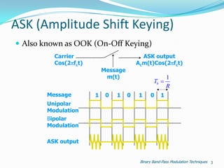
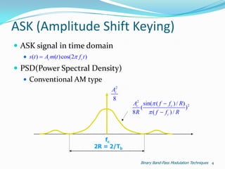

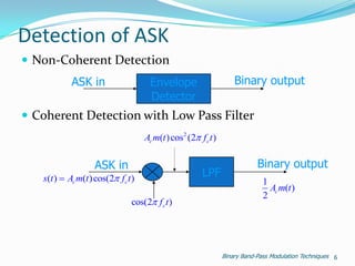
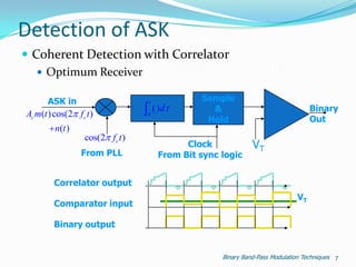
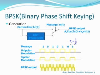
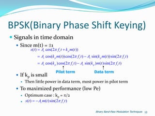
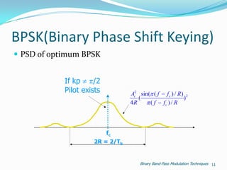
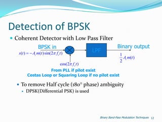
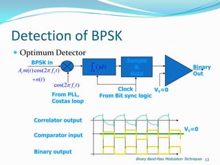
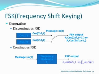
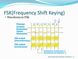

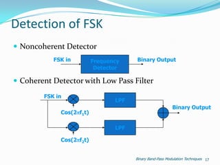
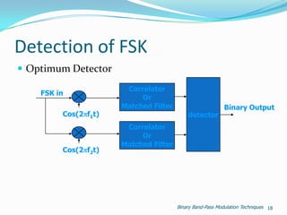


The document outlines various digital modulation techniques including ASK, BPSK, and FSK. It describes how each technique generates and detects modulated signals. ASK encodes data in signal amplitude levels. BPSK uses two phase shift keying to encode bits. FSK encodes data by shifting the carrier frequency between two values. Optimum detection requires coherent demodulation that correlates the received signal with a reference carrier.