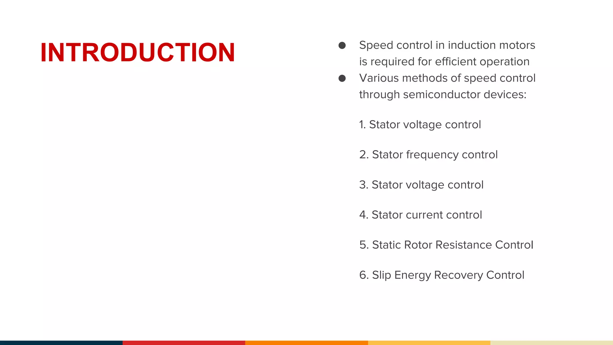
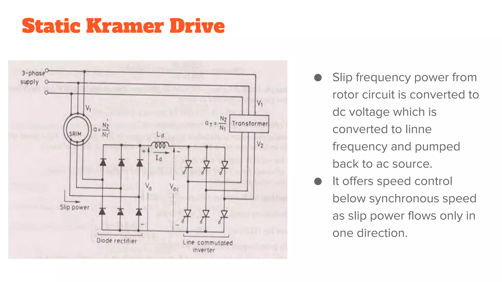
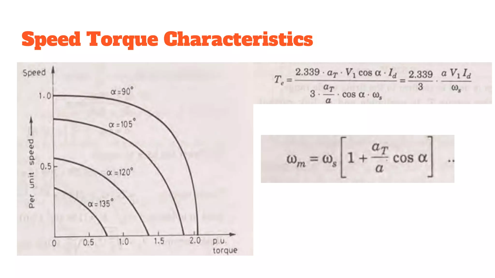
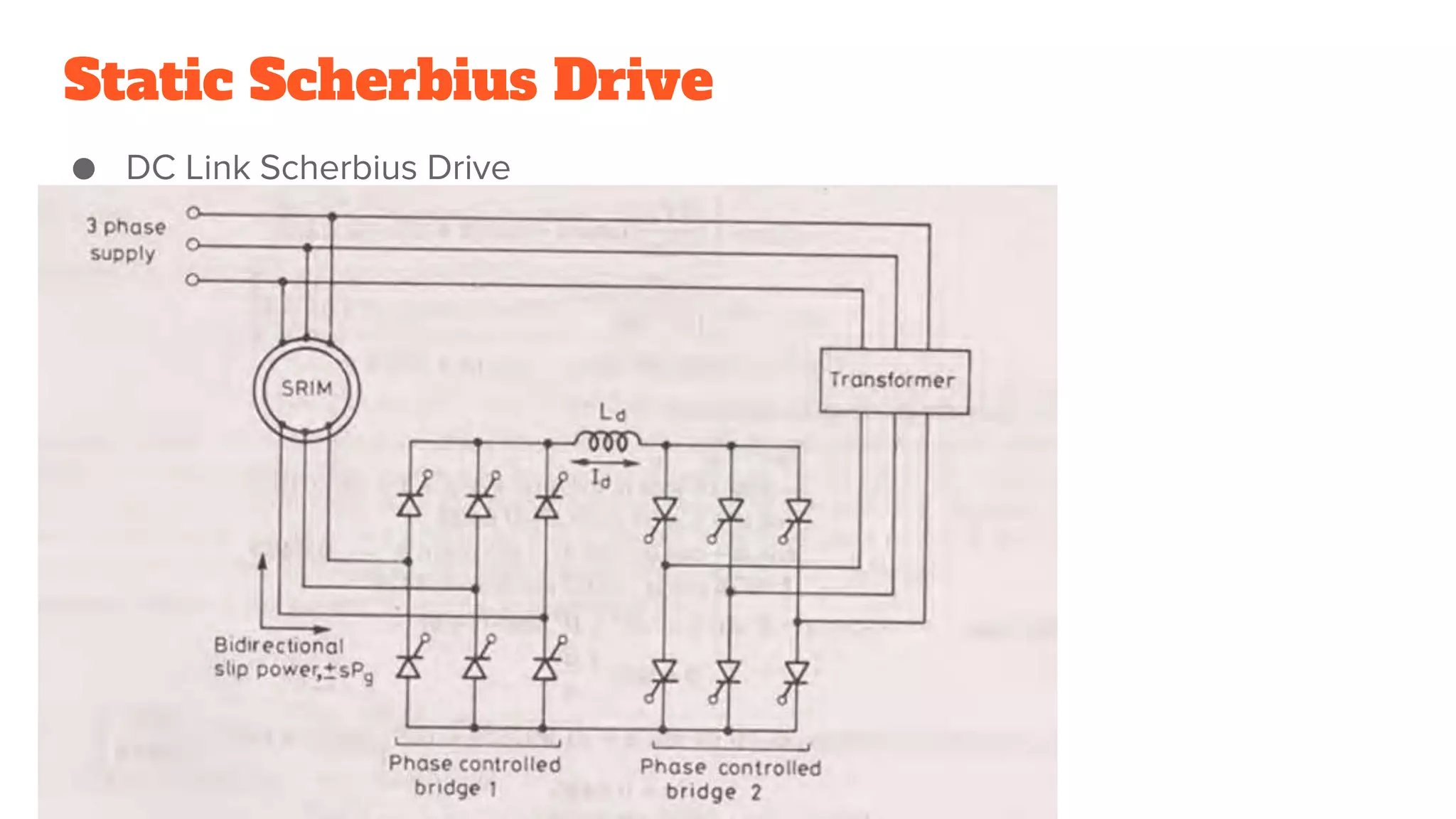
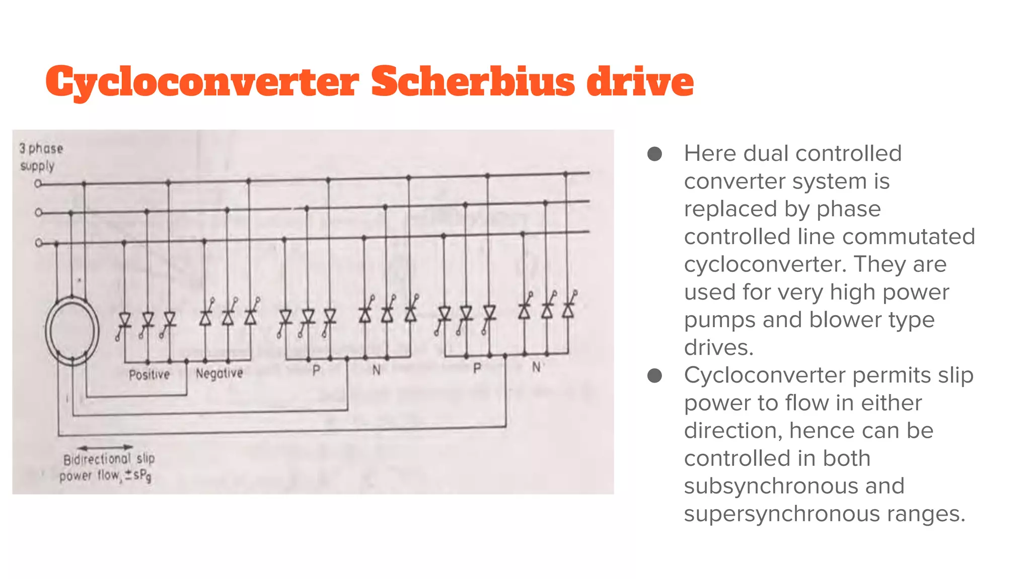
Speed control in induction motors is required for efficient operation
Various methods of speed control through semiconductor devices:
1. Stator voltage control
2. Stator frequency control
3. Stator voltage control
4. Stator current control
5. Static Rotor Resistance Control
6. Slip Energy Recovery Control
2. INTRODUCTION ● Speed control in induction motors
is required for efficient operation
● Various methods of speed control
through semiconductor devices:
1. Stator voltage control
2. Stator frequency control
3. Stator voltage control
4. Stator current control
5. Static Rotor Resistance Control
6. Slip Energy Recovery Control
3. STATIC ROTOR RESISTANCE CONTROL
By varying rotor circuit resistance R2, motor torque can be controlled. It can also
control starting torque and starting current.
4. ● Three phase resistor is
replaced by three phase
diode rectifier, chopper and
one resistor.
● Function of inductor Ld is to
smoothen current Id
● GTO chopper allows
effective rotor circuit
resistance to be varied for
speed control of SRIM.
● Diode rectifier converts slip
frequency input power to dc
at its output terminals.
5. Working:
● When chopper is on, Vdc=Vd=0,
resistance R gets short circuited.
● When chopper is off, Vdc=Vd and
resistance in rotor circuit is R.
6. Disadvantages:
● Reduced efficiency at low speeds.
● Speed changes widely with load variation
● Voltages and currents are imbalanced if R2 not equal
7. Slip Power
Recovery
Schemes
● In this chopper method of speed control
of SRIM, slip power is dissipated in
external resistance and it leads to poor
efficiency of drive. But instead of
wasting slip power in rotor circuit
resistance, it can be converted by
various schemes for speed control of
SRIM.
● They are of two types:
1. Static Kramer drive
2. Static Scherbius drive
8. Static Kramer Drive
● Slip frequency power from
rotor circuit is converted to
dc voltage which is
converted to linne
frequency and pumped
back to ac source.
● It offers speed control
below synchronous speed
as slip power flows only in
one direction.
11. Subsynchronous Speed Control
● Slip power is removed from rotor circuit and is pumped back into ac supply.
● Bridge 1 has firing angle less than 90 whereas bridge 2 has firing angle greater
than 90. Bridge 1 works as rectifier and bridge 2 as line commutated inverter
for subsynchronous motor control. Slip power flows from rotor circuit to bridge
1 then 2 , transformer and supply.
12. Supersynchronous Speed Control
● Additional power is fed to rotor circuit at slip frequency.
● Bridge 1 works as line commutated inverter with firing angle greater than 90
and bridge 2 as rectifier with firing angle less than 90. Power flows in opposite
direction
13. Disadvantages
● Near synchronous speed, slip frequency emfs are insufficient for natural
commutation of SCR, hence force commutation is used due to which above
speed operation complicates static converter system and cancels advantages
of simplicity and economy of the drive.
● Scherbius drive is expensive than Static Kramer drive because 6 diodes are
replaced by 6 SCRs and their controlled circuitry.
14. Cycloconverter Scherbius drive
● Here dual controlled
converter system is
replaced by phase
controlled line commutated
cycloconverter. They are
used for very high power
pumps and blower type
drives.
● Cycloconverter permits slip
power to flow in either
direction, hence can be
controlled in both
subsynchronous and
supersynchronous ranges.