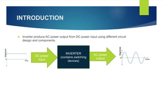
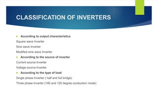
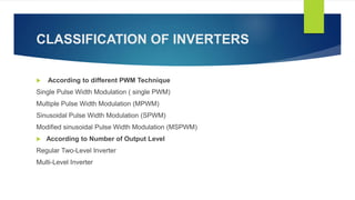
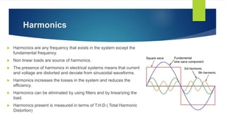
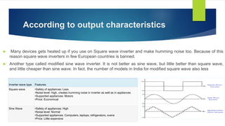
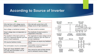
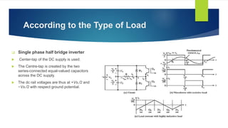
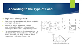
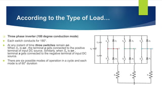
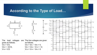
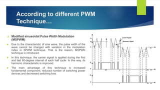
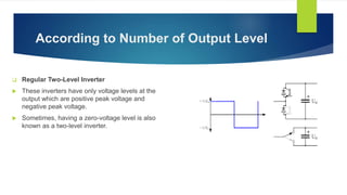
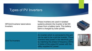
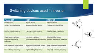
Presented by
SOMU GUPTA
(Electrical and Electronics Engineering )
INVERTERS
TYPES AND APPLICATIONS
IEEE PELS
DAY JUNE 20
2019
CONTENT
 Introduction
 History of Inverters
 Conventional Inverters
 Classification of Inverters
 Harmonics
 Types of PV Inverters
 Switching devices used in Inverter
 Recent trends in Inverter
 Applications
INTRODUCTION
 Inverter produce AC power output from DC power input using different circuit
design and components.
INVERTER
(contains switching
devices)
DC power
input
AC power
output
HISTORY OF INVERTERS
 The earliest Inverter was the motor generator, which was developed to serve the need of Ward
War II.
 The popular brand was Redi-line, which is still around today.
 The output was inefficient and requires 30 Amp to start and had no startup surge capacity.
 Tripp light company founded in 1922 produced automobile headlights that includes electronic
inverter
 The early unit used mechanical vibrator to oscillate DC power into square wave AC.
 In early 1966, solid state transistors replaced mechanical vibrator
 The unregulated square wave could operate only resistive load but It had no surge power for
starting motors and had problem of frequency control.
 In 1979, Vanner company introduced their first 1000Watt modified sine wave Inverter used in
ambulances.
 In 1986 Vanner introduced Inverter model included microprocessor control unit.
CLASSIFICATION OF INVERTERS
 According to output characteristics
Square wave Inverter
Sine wave Inverter
Modified sine wave Inverter
 According to the source of inverter
Current source Inverter
Voltage source Inverter
 According to the type of load
Single phase Inverter ( half and full bridge)
Three phase Inverter (180 and 120 degree conduction mode)
CLASSIFICATION OF INVERTERS
 According to different PWM Technique
Single Pulse Width Modulation ( single PWM)
Multiple Pulse Width Modulation (MPWM)
Sinusoidal Pulse Width Modulation (SPWM)
Modified sinusoidal Pulse Width Modulation (MSPWM)
 According to Number of Output Level
Regular Two-Level Inverter
Multi-Level Inverter
Harmonics
 Harmonics are any frequency that exists in the system except the
fundamental frequency.
 Non linear loads are source of harmonics.
 The presence of harmonics in electrical systems means that current
and voltage are distorted and deviate from sinusoidal waveforms.
 Harmonics increases the losses in the system and reduces the
efficiency.
 Harmonics can be eliminated by using filters and by linearizing the
load.
 Harmonics present is measured in terms of T.H.D ( Total Harmonic
Distortion)
According to output characteristics
 Many devices gets heated up if you use on Square wave inverter and make humming noise too. Because of this
reason square wave inverters in few European countries is banned.
 Another type called modified sine wave inverter. It is not better as sine wave, but little better than square wave,
and little cheaper than sine wave. In fact, the number of models in India for modified square wave also less
Inverter wave type Features
Square wave •Safety of appliances: Less
•Noise level: High, creates humming noise in inverter as well as in appliances
•Supported appliances: Motors
•Price: Economical
Sine Wave •Safety of appliances: High
•Noise level: Normal
•Supported appliances: Computers, laptops, refrigerators, ovens
•Price: Little expensive
According to Source of Inverter
VSI CSI
VSI is fed from a DC voltage source
having small or negligible impedance.
CSI is fed with current from a DC
voltage source of high impedance.
Input voltage is maintained constant The input current is constant.
Output voltage does not dependent on
the load
The amplitude of output current is
independent of the load.
The waveform of the load current as
well as its magnitude depends upon the
nature of load impedance.
The magnitude of output voltage and its
waveform depends upon the nature of
the load impedance.
VSI requires feedback diodes
The CSI does not require any feedback
diodes.
The commutation circuit is complicated
Commutation circuit is simple as it
contains only capacitors.
Power BJT, Power MOSFET, IGBT,
GTO with self commutation can be
used in the circuit.
They cannot be used as these devices
have to withstand reverse voltage.
According to the Type of Load
 Single phase half bridge inverter
 Center-tap of the DC supply is used.
 The Centre-tap is created by the two
series-connected equal-valued capacitors
across the DC supply.
 The dc rail voltages are thus at +Vs./2 and
−Vs./2 with respect ground potential.
According to the Type of Load…
 Single phase full bridge inverter
 In this circuit four switches are used and the DC supply
center-tap is not required.
 Switches Q1 and Q2 are switched together
while switches Q3 and Q4 are switched together
alternately to Q1 and Q2 in a complementary manner.
 The four feedback diodes D1-D4 conduct currents. The
output load voltage alternates between +Vs., when Q1
and Q2 are on and –Vs., when Q3 and Q4 are on,
irrespective of the direction of current flow.
According to the Type of Load…
 Three phase inverter (180 degree conduction mode)
 Each switch conducts for 180°.
 At any instant of time three switches remain on .
When S1 is on , the terminal a gets connected to the positive
terminal of input DC source. Similarly, when S4 is on ,
terminal a gets connected to the negative terminal of input DC
source.
 There are six possible modes of operation in a cycle and each
mode is of 60° duration
According to the Type of Load…
The load voltages are
gives as follows;
VAN = V/3,
VBN = −2V/3,
VCN = V/3
The line voltages are given
as follows;
VAB = VAN − VBN = V,
VBC = VBN − VCN = −V,
VCA = VCN − VAN = 0
According to the Type of Load…
 Three phase inverter (120 degree conduction mode)
 Each switch is in a conduction state for 120°.
 The terminal A on the load is connected to the positive end while the
terminal B is connected to the negative end of the source. The
terminal C on the load is in a condition called floating state.
 Most suitable for a delta connection in a load because it results in a
six-step type of waveform across any of its phases.
Phase voltages = Line voltages
VAB = V
VBC = −V/2
VCA = −V/2
 Advantage of 120 over 180 degree mode is that it can be used for
inductive loads also.
According to Different PWM Technique
 Single Pulse Width Modulation
 The reference signal is square wave signal and the carrier
signal is triangular wave signal.
 The gate pulse for the switches is generated by comparing
the reference signal and carrier signal.
 The frequency of output voltage is controlled by the
frequency of the reference signal.
 The modulation index can be defined as Ar/Ac.
 The main drawback of this technique is high harmonic
content.
According to Different PWM
Technique…
 Multiple Pulse Width Modulation (MPWM)
 Number of pulses are used in each half cycle of the
output voltage.
 The output frequency is controlled by controlling the
frequency of the carrier signal.
According to Different PWM
Technique…
 Sinusoidal Pulse Width Modulation (SPWM)
 This control technique is widely used in industrial
applications.
 The reference signal is a sine wave signal.
 The gate pulse for the switches is generated by
comparing the sine wave reference signal with the
triangular carrier wave.
 The width of each pulse varies with variation of
amplitude of the sine wave.
 The frequency of output waveform is the same as the
frequency of the reference signal.
According to different PWM
Technique…
 Modified sinusoidal Pulse Width Modulation
(MSPWM)
 Due to the characteristic of sine wave, the pulse width of the
wave cannot be changed with variation in the modulation
index in SPWM technique. That is the reason, MSPWN
technique is introduced.
 In this technique, the carrier signal is applied during the first
and last 60-degree interval of each half cycle. In this way, its
harmonic characteristic is improved.
 The main advantage of this technique is increased
fundamental component, reduced number of switching power
devices and decreased switching loss.
According to Number of Output Level
 Regular Two-Level Inverter
 These inverters have only voltage levels at the
output which are positive peak voltage and
negative peak voltage.
 Sometimes, having a zero-voltage level is also
known as a two-level inverter.
According to Number of Output
Level…
 Multi-Level Inverter
These inverters can have multiple voltage levels at the
output. The multi-level inverter is divided into four
types.
- Flying capacitor Inverter
- Diode-clamped Inverter
- Hybrid Inverter
- Cascade H-type Inverter
Types of PV Inverters
Off Grid Inverters/ stand alone
Inverters
These inverters are used in isolated
systems wherein the Inverter is fed DC
power from a battery bank. This battery
bank is charged by solar panels.
Grid Tie Inverters
An inverter which is connected to the grid
can be said to be a grid tie Inverter. These
inverters feed power in the electricity grid
by matching the phase & frequency (50Hz
in India) of the output AC power with the
utility supplied AC power.
Switching devices used in inverter
Power BJT IGBT MOSFET
Bipolar device Bipolar device Unipolar device
Current controlled device Voltage controlled device Voltage controlled device
Has low input impedance Has high input impedance Has high input impedance
Higher switching losses Low switching losses Low switching losses
Negative temperature
coefficient
Positive temperature coefficient Positive temperature coefficient
Low conduction power losses High conduction power losses High conduction power losses
Low switching frequency High switching frequency Very high switching frequency
Recent Trends in Inverters
 Power Quality Improvement (e.g. STATCOM)
 Optimum allocation of RES
 Power Equilibrium
 Energy Storage
 Sensors
 Protection
Smart Inverter
Applications
 PV systems
 Wind turbines and micro turbines
 Variable frequency drives
 Uninterruptible power supplies
 Electronic ballast and induction heaters
 HVDC power transmission
And many more…
Thank you!

Inverter

  • 1.
    Presented by SOMU GUPTA (Electricaland Electronics Engineering ) INVERTERS TYPES AND APPLICATIONS IEEE PELS DAY JUNE 20 2019
  • 2.
    CONTENT  Introduction  Historyof Inverters  Conventional Inverters  Classification of Inverters  Harmonics  Types of PV Inverters  Switching devices used in Inverter  Recent trends in Inverter  Applications
  • 3.
    INTRODUCTION  Inverter produceAC power output from DC power input using different circuit design and components. INVERTER (contains switching devices) DC power input AC power output
  • 4.
    HISTORY OF INVERTERS The earliest Inverter was the motor generator, which was developed to serve the need of Ward War II.  The popular brand was Redi-line, which is still around today.  The output was inefficient and requires 30 Amp to start and had no startup surge capacity.  Tripp light company founded in 1922 produced automobile headlights that includes electronic inverter  The early unit used mechanical vibrator to oscillate DC power into square wave AC.  In early 1966, solid state transistors replaced mechanical vibrator  The unregulated square wave could operate only resistive load but It had no surge power for starting motors and had problem of frequency control.  In 1979, Vanner company introduced their first 1000Watt modified sine wave Inverter used in ambulances.  In 1986 Vanner introduced Inverter model included microprocessor control unit.
  • 5.
    CLASSIFICATION OF INVERTERS According to output characteristics Square wave Inverter Sine wave Inverter Modified sine wave Inverter  According to the source of inverter Current source Inverter Voltage source Inverter  According to the type of load Single phase Inverter ( half and full bridge) Three phase Inverter (180 and 120 degree conduction mode)
  • 6.
    CLASSIFICATION OF INVERTERS According to different PWM Technique Single Pulse Width Modulation ( single PWM) Multiple Pulse Width Modulation (MPWM) Sinusoidal Pulse Width Modulation (SPWM) Modified sinusoidal Pulse Width Modulation (MSPWM)  According to Number of Output Level Regular Two-Level Inverter Multi-Level Inverter
  • 7.
    Harmonics  Harmonics areany frequency that exists in the system except the fundamental frequency.  Non linear loads are source of harmonics.  The presence of harmonics in electrical systems means that current and voltage are distorted and deviate from sinusoidal waveforms.  Harmonics increases the losses in the system and reduces the efficiency.  Harmonics can be eliminated by using filters and by linearizing the load.  Harmonics present is measured in terms of T.H.D ( Total Harmonic Distortion)
  • 8.
    According to outputcharacteristics  Many devices gets heated up if you use on Square wave inverter and make humming noise too. Because of this reason square wave inverters in few European countries is banned.  Another type called modified sine wave inverter. It is not better as sine wave, but little better than square wave, and little cheaper than sine wave. In fact, the number of models in India for modified square wave also less Inverter wave type Features Square wave •Safety of appliances: Less •Noise level: High, creates humming noise in inverter as well as in appliances •Supported appliances: Motors •Price: Economical Sine Wave •Safety of appliances: High •Noise level: Normal •Supported appliances: Computers, laptops, refrigerators, ovens •Price: Little expensive
  • 9.
    According to Sourceof Inverter VSI CSI VSI is fed from a DC voltage source having small or negligible impedance. CSI is fed with current from a DC voltage source of high impedance. Input voltage is maintained constant The input current is constant. Output voltage does not dependent on the load The amplitude of output current is independent of the load. The waveform of the load current as well as its magnitude depends upon the nature of load impedance. The magnitude of output voltage and its waveform depends upon the nature of the load impedance. VSI requires feedback diodes The CSI does not require any feedback diodes. The commutation circuit is complicated Commutation circuit is simple as it contains only capacitors. Power BJT, Power MOSFET, IGBT, GTO with self commutation can be used in the circuit. They cannot be used as these devices have to withstand reverse voltage.
  • 10.
    According to theType of Load  Single phase half bridge inverter  Center-tap of the DC supply is used.  The Centre-tap is created by the two series-connected equal-valued capacitors across the DC supply.  The dc rail voltages are thus at +Vs./2 and −Vs./2 with respect ground potential.
  • 11.
    According to theType of Load…  Single phase full bridge inverter  In this circuit four switches are used and the DC supply center-tap is not required.  Switches Q1 and Q2 are switched together while switches Q3 and Q4 are switched together alternately to Q1 and Q2 in a complementary manner.  The four feedback diodes D1-D4 conduct currents. The output load voltage alternates between +Vs., when Q1 and Q2 are on and –Vs., when Q3 and Q4 are on, irrespective of the direction of current flow.
  • 12.
    According to theType of Load…  Three phase inverter (180 degree conduction mode)  Each switch conducts for 180°.  At any instant of time three switches remain on . When S1 is on , the terminal a gets connected to the positive terminal of input DC source. Similarly, when S4 is on , terminal a gets connected to the negative terminal of input DC source.  There are six possible modes of operation in a cycle and each mode is of 60° duration
  • 13.
    According to theType of Load… The load voltages are gives as follows; VAN = V/3, VBN = −2V/3, VCN = V/3 The line voltages are given as follows; VAB = VAN − VBN = V, VBC = VBN − VCN = −V, VCA = VCN − VAN = 0
  • 14.
    According to theType of Load…  Three phase inverter (120 degree conduction mode)  Each switch is in a conduction state for 120°.  The terminal A on the load is connected to the positive end while the terminal B is connected to the negative end of the source. The terminal C on the load is in a condition called floating state.  Most suitable for a delta connection in a load because it results in a six-step type of waveform across any of its phases. Phase voltages = Line voltages VAB = V VBC = −V/2 VCA = −V/2  Advantage of 120 over 180 degree mode is that it can be used for inductive loads also.
  • 15.
    According to DifferentPWM Technique  Single Pulse Width Modulation  The reference signal is square wave signal and the carrier signal is triangular wave signal.  The gate pulse for the switches is generated by comparing the reference signal and carrier signal.  The frequency of output voltage is controlled by the frequency of the reference signal.  The modulation index can be defined as Ar/Ac.  The main drawback of this technique is high harmonic content.
  • 16.
    According to DifferentPWM Technique…  Multiple Pulse Width Modulation (MPWM)  Number of pulses are used in each half cycle of the output voltage.  The output frequency is controlled by controlling the frequency of the carrier signal.
  • 17.
    According to DifferentPWM Technique…  Sinusoidal Pulse Width Modulation (SPWM)  This control technique is widely used in industrial applications.  The reference signal is a sine wave signal.  The gate pulse for the switches is generated by comparing the sine wave reference signal with the triangular carrier wave.  The width of each pulse varies with variation of amplitude of the sine wave.  The frequency of output waveform is the same as the frequency of the reference signal.
  • 18.
    According to differentPWM Technique…  Modified sinusoidal Pulse Width Modulation (MSPWM)  Due to the characteristic of sine wave, the pulse width of the wave cannot be changed with variation in the modulation index in SPWM technique. That is the reason, MSPWN technique is introduced.  In this technique, the carrier signal is applied during the first and last 60-degree interval of each half cycle. In this way, its harmonic characteristic is improved.  The main advantage of this technique is increased fundamental component, reduced number of switching power devices and decreased switching loss.
  • 19.
    According to Numberof Output Level  Regular Two-Level Inverter  These inverters have only voltage levels at the output which are positive peak voltage and negative peak voltage.  Sometimes, having a zero-voltage level is also known as a two-level inverter.
  • 20.
    According to Numberof Output Level…  Multi-Level Inverter These inverters can have multiple voltage levels at the output. The multi-level inverter is divided into four types. - Flying capacitor Inverter - Diode-clamped Inverter - Hybrid Inverter - Cascade H-type Inverter
  • 21.
    Types of PVInverters Off Grid Inverters/ stand alone Inverters These inverters are used in isolated systems wherein the Inverter is fed DC power from a battery bank. This battery bank is charged by solar panels. Grid Tie Inverters An inverter which is connected to the grid can be said to be a grid tie Inverter. These inverters feed power in the electricity grid by matching the phase & frequency (50Hz in India) of the output AC power with the utility supplied AC power.
  • 22.
    Switching devices usedin inverter Power BJT IGBT MOSFET Bipolar device Bipolar device Unipolar device Current controlled device Voltage controlled device Voltage controlled device Has low input impedance Has high input impedance Has high input impedance Higher switching losses Low switching losses Low switching losses Negative temperature coefficient Positive temperature coefficient Positive temperature coefficient Low conduction power losses High conduction power losses High conduction power losses Low switching frequency High switching frequency Very high switching frequency
  • 23.
    Recent Trends inInverters  Power Quality Improvement (e.g. STATCOM)  Optimum allocation of RES  Power Equilibrium  Energy Storage  Sensors  Protection Smart Inverter
  • 24.
    Applications  PV systems Wind turbines and micro turbines  Variable frequency drives  Uninterruptible power supplies  Electronic ballast and induction heaters  HVDC power transmission And many more…
  • 25.

Editor's Notes

  • #7 Invertor is good.