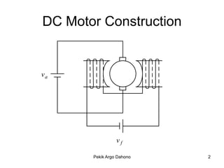
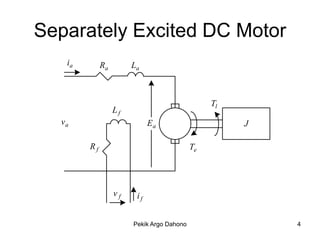
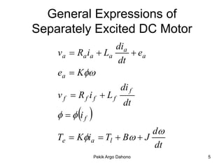
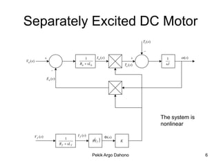
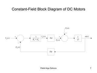
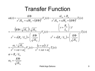
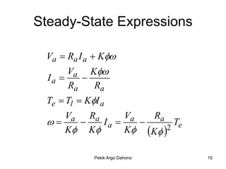
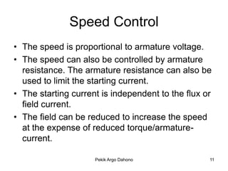
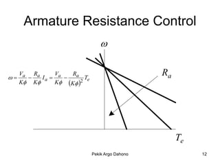
DC Motor Characteristics

        Pekik Argo Dahono
Institute of Technology Bandung
DC Motor Construction


va


                 vf

       Pekik Argo Dahono   2
DC Motor Features
• Depending on the connection between armature and
  field windings, a dc motor can be classified as separately
  excited and series excited dc motors.
• In small dc motors, the field can be permanent magnet.
• The armature is usually located on the rotor and the field
  is on the stator.
• Due to the action of commutator and brush, the mmf
  generated by the armature current is perpendicular to
  the flux generated by field winding.
• At present, most of dc motor applications are replaced
  by ac motors.


                        Pekik Argo Dahono                  3
Separately Excited DC Motor
   ia        Ra        La


                                                Tl
                  Lf
  va                         Ea                      J

        Rf                                 Te


                  vf    if


                       Pekik Argo Dahono                 4
General Expressions of
Separately Excited DC Motor
                    dia
    va  Ra ia  La      ea
                    dt
    ea  K
                                 di f
    vf  Rf if  Lf
                                  dt
       i f   
                            d
    Te  Kia  Tl  B  J
                            dt
                     Pekik Argo Dahono   5
Separately Excited DC Motor
                                                                                             Tl (s )

                                                                                             _

                                                1            I a (s )                                   1    (s )
Va (s )
                                              Ra  sLa                             Te (s )               sJ
                         _

                     E a (s )


                                                                                                       The system is
                                                                                                       nonlinear
                                             I f (s )
          V f (s )                                                     (s )
                                    1                     i f               K
                                R f  sL f


                                                         Pekik Argo Dahono                                             6
Constant-Field Block Diagram of DC Motors


                                                             Tl (s )

                                                             _

                         1        I a (s )                            1    (s )
Va (s )                                       K
                       Ra  sLa                    Te (s )             sJ
                _

            E a (s )

                                              K


                                  Pekik Argo Dahono                                  7
Motor Characteristics
• The system is linear when the field is
  constant.
• Under this condition, the torque is
  proportional to armature current.


                  Pekik Argo Dahono        8
Transfer Function
                    K                                sLa  Ra
 (s)                              V (s)                                Tl ( s )
          s JLa  sJRa  K                 s JLa  sJRa  K 
           2                       2 a          2                    2


                                                           Ra 


         K /       
                 JLa /     JLa
                                    Va ( s ) 
                                                      s 
                                                      
                                                           La 
                                                                / J
                                                                                  Tl ( s )
                                  2                                            2
                          K                                    K     
    s  s Ra / La   
     2
                                               s  s Ra / La   
                                                2                          
                           JLa                                   JL     
                                                                   a    

 2
   o / JLa              s    / J T ( s)
              Va ( s )  2
  s  s  o
            2
                        s  s  o  2 l


  Ra / La
         K
o 
          JLa
                                  Pekik Argo Dahono                                           9
Steady-State Expressions

 Va  Ra I a  K
      Va K
 Ia      
      Ra      Ra
 Te  Tl  KI a
      Va Ra          Va   Ra
             Ia           Te
      K K          K K 2

            Pekik Argo Dahono       10
Speed Control
• The speed is proportional to armature voltage.
• The speed can also be controlled by armature
  resistance. The armature resistance can also be
  used to limit the starting current.
• The starting current is independent to the flux or
  field current.
• The field can be reduced to increase the speed
  at the expense of reduced torque/armature-
  current.

                     Pekik Argo Dahono             11
Armature Resistance Control
                                



     Va Ra
       
               V
           Ia  a 
                    Ra
                        T
                                                 Ra
     K K     K K 2 e


                                                      Te
                             Pekik Argo Dahono             12
Armature Voltage Control
                             
                                         Va


                                              Te


     Va Ra     V    Ra
        Ia  a      T
     K K     K K 2 e

                         Pekik Argo Dahono         13
Field Control
                         

                                                 


     Va Ra     V    Ra
        Ia  a      T
     K K     K K 2 e


                                                     Te
                             Pekik Argo Dahono            14
Control of Separately Excited DC Motor
       Constant Torque          Constant Power


           Va                                If
                      Te  KI a
                      P  Te

                                                 

                  Pekik Argo Dahono                  15
Control Characteristics
• Below base speed, the speed is controlled by
  the armature voltage at maximum field current
  (to maintain maximum torque/armature-current
  or constant torque capability).
• Above base-speed, the speed can only be
  increased by reducing the field current (constant
  power capability). The maximum speed is limited
  by the mechanical capability and armature
  reaction.

                    Pekik Argo Dahono            16
Four-Quadrant Operation
           


                            Te


        Pekik Argo Dahono        17
Braking of DC Motors
• Dynamic braking : The kinetic energy is
  dissipated to the braking resistor.
• Counter current braking or plugging: The kinetic
  energy is dissipated in the machine and current-
  limiting resistor. The current can be so high with
  braking method.
• Regenerative braking. The kinetic energy is sent
  back to the source. This method can only be
  used when the source is able to receive the
  regenerated energy.

                     Pekik Argo Dahono             18
Control of Separately Excited DC Motor

  AC source

              M         G             M


                  Pekik Argo Dahono       19
Ward-Leonard Characteristics
• Fully four-quadrant operation is possible.
• Below base speed, the motor field current is
  constant at maximum value and the speed is
  controlled by the generator field current.
• Above base speed, the motor speed is
  increased by reducing the motor field current.
• If the ac motor is a synchronous motor, the ac
  power factor is controllable.
• No harmonics are generated.
• The system is large, expensive, less responsive,
  and needs a lot of maintenance.

                    Pekik Argo Dahono            20
Series DC Motors
• This motor is commonly used in dc electric
  traction.
• This motor can be used as ac comutator
  motor.
• This motor can be operated as a universal
  motor.


                 Pekik Argo Dahono         21
Steady-State Characteristics
                                      • Speed can be controlled by
Ia  I f                                controlling the armature
                                        voltage.
Assume   K f I a                    • Speed can also be controlled
Te  Tl  KK f I a
                 2                      by using the armature
                                        resistance and field diverter.
   Va  Ra I a    Va       Ra         • In electric traction, series
                      
      K         KK f I a KK f          parallel connection is also
                                        used to control the speed.
      Va           Ra
                                    • A low frequency ac supply is
    KK f Te       KK f                  desirable if the motor is
                                        operated as a series ac
                                        commutator motor.


                            Pekik Argo Dahono                            22
Braking Methods
•   Mechanical Braking
•   Counter plug                      Te  Kia
•   Dynamic braking
•   Regenerative Braking


                  Pekik Argo Dahono               23
Counter Plug


     va  E
ia 
       Ra
Te   Kia

                 Pekik Argo Dahono   24
Dynamic Braking


        E
ia 
     Rb  Ra
Te   Kia

               Pekik Argo Dahono   25
Regenerative Braking


     E  va
ia 
      Ra
Te   Kia

              Pekik Argo Dahono   26
The End

DC motors

  • 1.
    DC Motor Characteristics Pekik Argo Dahono Institute of Technology Bandung
  • 2.
    DC Motor Construction va vf Pekik Argo Dahono 2
  • 3.
    DC Motor Features •Depending on the connection between armature and field windings, a dc motor can be classified as separately excited and series excited dc motors. • In small dc motors, the field can be permanent magnet. • The armature is usually located on the rotor and the field is on the stator. • Due to the action of commutator and brush, the mmf generated by the armature current is perpendicular to the flux generated by field winding. • At present, most of dc motor applications are replaced by ac motors. Pekik Argo Dahono 3
  • 4.
    Separately Excited DCMotor ia Ra La Tl Lf va Ea J Rf Te vf if Pekik Argo Dahono 4
  • 5.
    General Expressions of SeparatelyExcited DC Motor dia va  Ra ia  La  ea dt ea  K di f vf  Rf if  Lf dt    i f  d Te  Kia  Tl  B  J dt Pekik Argo Dahono 5
  • 6.
    Separately Excited DCMotor Tl (s ) _  1 I a (s )  1  (s ) Va (s ) Ra  sLa Te (s ) sJ _ E a (s ) The system is nonlinear I f (s ) V f (s )  (s ) 1  i f  K R f  sL f Pekik Argo Dahono 6
  • 7.
    Constant-Field Block Diagramof DC Motors Tl (s ) _  1 I a (s )  1  (s ) Va (s ) K Ra  sLa Te (s ) sJ _ E a (s ) K Pekik Argo Dahono 7
  • 8.
    Motor Characteristics • Thesystem is linear when the field is constant. • Under this condition, the torque is proportional to armature current. Pekik Argo Dahono 8
  • 9.
    Transfer Function K sLa  Ra  (s)  V (s)  Tl ( s ) s JLa  sJRa  K  s JLa  sJRa  K  2 2 a 2 2  Ra   K /  JLa / JLa Va ( s )  s    La  / J  Tl ( s ) 2 2  K    K  s  s Ra / La    2 s  s Ra / La    2   JLa   JL     a   2 o / JLa s    / J T ( s) Va ( s )  2 s  s  o 2 s  s  o 2 l   Ra / La K o  JLa Pekik Argo Dahono 9
  • 10.
    Steady-State Expressions Va Ra I a  K Va K Ia   Ra Ra Te  Tl  KI a Va Ra Va Ra   Ia   Te K K  K K 2 Pekik Argo Dahono 10
  • 11.
    Speed Control • Thespeed is proportional to armature voltage. • The speed can also be controlled by armature resistance. The armature resistance can also be used to limit the starting current. • The starting current is independent to the flux or field current. • The field can be reduced to increase the speed at the expense of reduced torque/armature- current. Pekik Argo Dahono 11
  • 12.
    Armature Resistance Control   Va Ra  V Ia  a  Ra T Ra K K K K 2 e Te Pekik Argo Dahono 12
  • 13.
    Armature Voltage Control  Va Te Va Ra V Ra   Ia  a  T K K K K 2 e Pekik Argo Dahono 13
  • 14.
    Field Control   Va Ra V Ra   Ia  a  T K K K K 2 e Te Pekik Argo Dahono 14
  • 15.
    Control of SeparatelyExcited DC Motor Constant Torque Constant Power Va If Te  KI a P  Te  Pekik Argo Dahono 15
  • 16.
    Control Characteristics • Belowbase speed, the speed is controlled by the armature voltage at maximum field current (to maintain maximum torque/armature-current or constant torque capability). • Above base-speed, the speed can only be increased by reducing the field current (constant power capability). The maximum speed is limited by the mechanical capability and armature reaction. Pekik Argo Dahono 16
  • 17.
    Four-Quadrant Operation  Te Pekik Argo Dahono 17
  • 18.
    Braking of DCMotors • Dynamic braking : The kinetic energy is dissipated to the braking resistor. • Counter current braking or plugging: The kinetic energy is dissipated in the machine and current- limiting resistor. The current can be so high with braking method. • Regenerative braking. The kinetic energy is sent back to the source. This method can only be used when the source is able to receive the regenerated energy. Pekik Argo Dahono 18
  • 19.
    Control of SeparatelyExcited DC Motor AC source M G M Pekik Argo Dahono 19
  • 20.
    Ward-Leonard Characteristics • Fullyfour-quadrant operation is possible. • Below base speed, the motor field current is constant at maximum value and the speed is controlled by the generator field current. • Above base speed, the motor speed is increased by reducing the motor field current. • If the ac motor is a synchronous motor, the ac power factor is controllable. • No harmonics are generated. • The system is large, expensive, less responsive, and needs a lot of maintenance. Pekik Argo Dahono 20
  • 21.
    Series DC Motors •This motor is commonly used in dc electric traction. • This motor can be used as ac comutator motor. • This motor can be operated as a universal motor. Pekik Argo Dahono 21
  • 22.
    Steady-State Characteristics • Speed can be controlled by Ia  I f controlling the armature voltage. Assume   K f I a • Speed can also be controlled Te  Tl  KK f I a 2 by using the armature resistance and field diverter. Va  Ra I a Va Ra • In electric traction, series    K KK f I a KK f parallel connection is also used to control the speed. Va Ra   • A low frequency ac supply is KK f Te KK f desirable if the motor is operated as a series ac commutator motor. Pekik Argo Dahono 22
  • 23.
    Braking Methods • Mechanical Braking • Counter plug Te  Kia • Dynamic braking • Regenerative Braking Pekik Argo Dahono 23
  • 24.
    Counter Plug va  E ia  Ra Te   Kia Pekik Argo Dahono 24
  • 25.
    Dynamic Braking E ia  Rb  Ra Te   Kia Pekik Argo Dahono 25
  • 26.
    Regenerative Braking E  va ia  Ra Te   Kia Pekik Argo Dahono 26
  • 27.