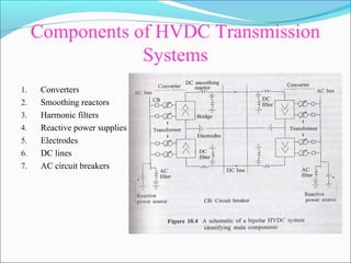
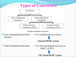
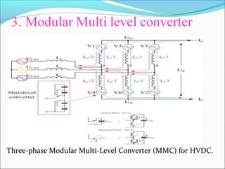
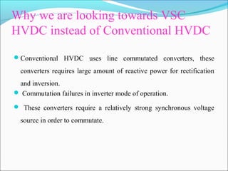
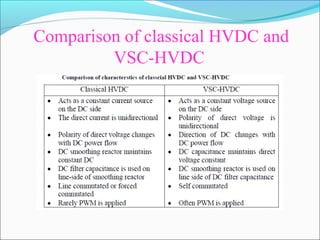
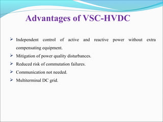
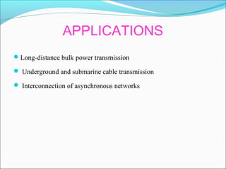
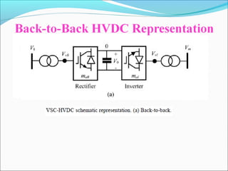
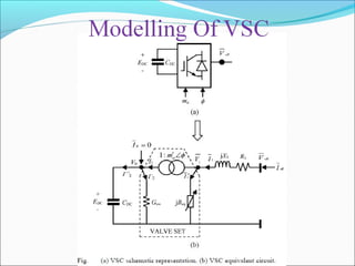
This document provides an overview of voltage source converters (VSC) for high voltage direct current (HVDC) transmission. It discusses the components and operation of VSC-HVDC systems, including different converter configurations like two-level, three-level, and modular multi-level converters. It also compares VSC-HVDC to conventional HVDC systems using line-commutated converters, noting advantages of VSC-HVDC like eliminating the need for reactive power compensation and reducing the risk of commutation failures.
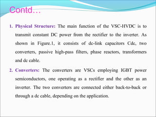
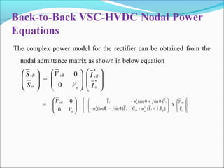
High Voltage Direct Current technology has certain characteristics which
make it especially attractive for transmission system applications. HVDC
transmission system is useful for long-distance transmission, bulk power delivery and
long submarine cable crossings and asynchronous interconnections. The study of
faults is essential for reasonable protection design because the faults will induce a
significant influence on operation of HVDC transmission system. This paper provides
the most dominant and frequent faults on the HVDC systems such as DC Line-to-
Ground fault and Line-to-Line fault on DC link and some common types of AC faults
occurs in overhead transmission system such as Line-to-Ground fault, Line-to-Line
fault and L-L-L fault. In HVDC system, faults on rectifier side or inverter side have
major affects on system stability. The various types of faults are considered in the
HVDC system which causes due to malfunctions of valves and controllers, misfire
and short circuit across the inverter station, flashover and three phase short circuit.
The various faults occurs at the converter station of a HVDC system and
Controlling action for those faults. Most of the studies have been conducted on line
faults. But faults on rectifier or inverter side of a HVDC system have great impact on
system stability. Faults considered are fire-through, misfire, and short circuit across
the inverter station, flashover, and a three-phase short circuit in the ac system. These
investigations are studied using matlab simulink models and the result represented in
the form of typical time responses.
These slides are all about Phasor Measurement Units (PMUs). An introduction to PMU is presented as a preliminary knowledge for the course 'Distribution Generation and Smart Grid'. Your valuable suggestions are welcome.
The concept of FACTS (Flexible Alternating Current Transmission System) refers to a family of power electronics-based devices able to enhance AC system controllability and stability and to increase power transfer capability.
HVDC (high-voltage direct current) is a highly efficient alternative for transmitting large amounts of electricity over long distances and for special purpose applications.
Introduction, equipment required for HVDC systems, Comparison of AC and DC Transmission, Limitations of HVDC transmission lines, reliability of HVDC systems, comparison of HVDC link with EHVAC link, HVDC system configuration and components, fundamental equations in HVDC system, HVDC links, converter theory and performance equation, valve characteristic, converter circuits, converter transformer testing, multi bridge converters, abnormal operation of HVDC system, control of HVDC system, harmonics and filters. Influence of AC system strength on AC/DC system interaction, response to AC and DC system faults, Concept of reactive power compensation- reactive Power balance in HVDC substations-Effect of angle of advance and extinction angle on reactive power requirement of converters.
Applications of power electronics in HVDCKabilesh K
Role of Power electronics in HVDC and Transmission system. What are the components of Power electronics used in HVDC. Types of HVDC Links. Advantages of HVDC over HVAC.
HVDC stands for High Voltage Direct Current and is today a well-proven technology employed for power transmission all over the world. In total about 70,000 MW HVDC transmission capacity is installed in more than 90 projects.
The development of the HVDC technology started in the late 1920s, and only after some 25 years of extensive development and pioneering work the first commercially operating scheme was commissioned in 1954.
Introduction, Operation of 12-pulse converter as receiving and sending terminals of HVDC system, Equipment required for HVDC System and their significance, Comparison of AC and DC transmission, Control of HVDC transmission
High Voltage Direct Current Transmission SystemNadeem Khilji
The development of HVDC (High Voltage Direct Current) transmission system dates back to the 1930s when mercury arc rectifiers were invented. Since the 1960s, HVDC transmission system is now a mature technology and has played a vital part in both long distance transmission and in the interconnection of systems. Transmitting power at high voltage and in DC form instead of AC is a new technology proven to be economic and simple in operation which is HVDC transmission. HVDC transmission systems, when installed, often form the backbone of an electric power system. They combine high reliability with a long useful life. An HVDC link avoids some of the disadvantages and limitations of AC transmission. HVDC transmission refers to that the AC power generated at a power plant is transformed into DC power before its transmission. At the inverter (receiving side), it is then transformed back into its original AC power and then supplied to each household. Such power transmission method makes it possible to transmit electric power in an economic way.
I have created this report for my final semester seminar at Poornima college of engineering Jaipur, electrical department. This report covers various chapters and other contents. feel free to download.
Note: some minor editsin format and a quick spelling check might be needed.
**content source is wikipedia and internet**
any thing you would like to suggest please let me know in the comments.
Water scarcity is the lack of fresh water resources to meet the standard water demand. There are two type of water scarcity. One is physical. The other is economic water scarcity.
Immunizing Image Classifiers Against Localized Adversary Attacksgerogepatton
This paper addresses the vulnerability of deep learning models, particularly convolutional neural networks
(CNN)s, to adversarial attacks and presents a proactive training technique designed to counter them. We
introduce a novel volumization algorithm, which transforms 2D images into 3D volumetric representations.
When combined with 3D convolution and deep curriculum learning optimization (CLO), itsignificantly improves
the immunity of models against localized universal attacks by up to 40%. We evaluate our proposed approach
using contemporary CNN architectures and the modified Canadian Institute for Advanced Research (CIFAR-10
and CIFAR-100) and ImageNet Large Scale Visual Recognition Challenge (ILSVRC12) datasets, showcasing
accuracy improvements over previous techniques. The results indicate that the combination of the volumetric
input and curriculum learning holds significant promise for mitigating adversarial attacks without necessitating
adversary training.
Saudi Arabia stands as a titan in the global energy landscape, renowned for its abundant oil and gas resources. It's the largest exporter of petroleum and holds some of the world's most significant reserves. Let's delve into the top 10 oil and gas projects shaping Saudi Arabia's energy future in 2024.
Overview of the fundamental roles in Hydropower generation and the components involved in wider Electrical Engineering.
This paper presents the design and construction of hydroelectric dams from the hydrologist’s survey of the valley before construction, all aspects and involved disciplines, fluid dynamics, structural engineering, generation and mains frequency regulation to the very transmission of power through the network in the United Kingdom.
Author: Robbie Edward Sayers
Collaborators and co editors: Charlie Sims and Connor Healey.
(C) 2024 Robbie E. Sayers
Cosmetic shop management system project report.pdfKamal Acharya
Buying new cosmetic products is difficult. It can even be scary for those who have sensitive skin and are prone to skin trouble. The information needed to alleviate this problem is on the back of each product, but it's thought to interpret those ingredient lists unless you have a background in chemistry.
Instead of buying and hoping for the best, we can use data science to help us predict which products may be good fits for us. It includes various function programs to do the above mentioned tasks.
Data file handling has been effectively used in the program.
The automated cosmetic shop management system should deal with the automation of general workflow and administration process of the shop. The main processes of the system focus on customer's request where the system is able to search the most appropriate products and deliver it to the customers. It should help the employees to quickly identify the list of cosmetic product that have reached the minimum quantity and also keep a track of expired date for each cosmetic product. It should help the employees to find the rack number in which the product is placed.It is also Faster and more efficient way.
CFD Simulation of By-pass Flow in a HRSG module by R&R Consult.pptxR&R Consult
CFD analysis is incredibly effective at solving mysteries and improving the performance of complex systems!
Here's a great example: At a large natural gas-fired power plant, where they use waste heat to generate steam and energy, they were puzzled that their boiler wasn't producing as much steam as expected.
R&R and Tetra Engineering Group Inc. were asked to solve the issue with reduced steam production.
An inspection had shown that a significant amount of hot flue gas was bypassing the boiler tubes, where the heat was supposed to be transferred.
R&R Consult conducted a CFD analysis, which revealed that 6.3% of the flue gas was bypassing the boiler tubes without transferring heat. The analysis also showed that the flue gas was instead being directed along the sides of the boiler and between the modules that were supposed to capture the heat. This was the cause of the reduced performance.
Based on our results, Tetra Engineering installed covering plates to reduce the bypass flow. This improved the boiler's performance and increased electricity production.
It is always satisfying when we can help solve complex challenges like this. Do your systems also need a check-up or optimization? Give us a call!
Work done in cooperation with James Malloy and David Moelling from Tetra Engineering.
More examples of our work https://www.r-r-consult.dk/en/cases-en/
2. Chapters
1. HVDC Transmission system
2. Voltage source converters
3. VSC-HVDC Transmission
4. Newton - Raphson method
5. Modelling of VSC
6. Test cases and results
7. Future scope
3.
4.
5. HVDC stands for High Voltage Direct Current. HVDC transmission is an
efficient technology designed to deliver large amount of electricity over long
distances with negligible losses.
The world’s first commercial HVDC link situated between the Swedish
mainland and the island Gotland was delivered by ABB in the year of 1954
with the capacity of 20MW, 100kv
INRTODUCTION
The longest HVDC link in the world is currently the Xiangjiaba–Shanghai.
It was built on owned by State Grid Corporation of China(SGCC)
Total length - 2071km
Power ratting - 6400MW
DC voltage - 800KV
6. HVDC IN INDIA
Back-to-Back
HVDC LINK CONNECTING
REGION
CAPACITY
(MW)
Vindyachal North – West 2 x 250
Chandrapur West – South 2 x 500
Vizag – I East – South 500
Sasaram East – North 500
Vizag – II East – South 500
7. NEEDS OF HVDC
As the load demand increases as the time progresses , there should be two
possibilities:
Either to increase the generation
To minimize the losses
The losses are occurred at various levels are Generating level, transmission
level and distribution level
So the losses at transmission level can be greatly reduced by HVDC
transmission
8. WHY TO PREFER HVDC THAN
HVAC?
Long distance transmission
5 times more energy transmits than AC(same lines)
Less losses (no inductance, capacitance).
Cost of transmission is low.
Maintenance & operation cost is low.
Initial cost is high but overall cost is low than ac.
10. HVDC System Configurations and
Components
HVDC links can be broadly classified into:
Monopolar links
Bipolar links
Homopolar links
Multi terminal links
Back-to-back links
Point-to-point links
11. Monopolar Links
It uses one conductor
The return path is provided by ground or water
Use of this system is mainly due to cost considerations
A metallic return may be used where earth resistivity is too
high
This configuration type is the first step towards a bipolar link
12. Bipolar Links
It uses two conductors, one positive and the other negative
Each terminal has two converters of equal rated voltage, connected in
series on the DC side
The junctions between the converters is grounded
Currents in the two poles are equal and there is no ground current
If one pole is isolated due to fault, the other pole can operate with
ground and carry half the rated load (or more using overload
capabilities of its converter line)
13. Homopolar Links
It has two or more conductors all having the same polarity, usually
negative
Since the corona effect in DC transmission lines is less for negative
polarity, homopolar link is usually operated with negative polarity
The return path for such a system is through ground
14. Multi terminal Links
There are more than two sets of converters like in the bipolar case.
Thus, converters one and three can operate as rectifiers while converter
two operates as an inverter.
Operating in the opposite order, converter two can operate as a rectifier
and converters one and three as inverters
15. Back-to-Back Links
In this case the two converter stations are located at the same site and no
transmission line or cable is required between the converter bridges.
The connection may be monopolar or bipolar.
The dc-link voltage is regulated by controlling the power flow to the ac
grid.
This system having fast control of the power flow.
16. Point-to-Point Links
This configuration is called as the point to point configuration, when the
converters are located in different regions and need to be connected
with a transmission line to transmit power form one converter side to
another.
In that case one converter acts as a rectifier, which provides the power
flow and another one acts an inverter which receives that power.
17. Components of HVDC Transmission
Systems
1. Converters
2. Smoothing reactors
3. Harmonic filters
4. Reactive power supplies
5. Electrodes
6. DC lines
7. AC circuit breakers
18. Components of HVDC Transmission Systems
Converters
They perform AC/DC and DC/AC conversion
They consist of valve bridges and transformers
Valve bridge consists of high voltage valves connected in a 6-pulse or 12-pulse
arrangement
The transformers are ungrounded such that the DC system will be able to establish its
own reference to ground
Smoothing reactors
They are high reactors with inductance as high as 1 H in series with each pole
They serve the following:
They decrease harmonics in voltages and currents in DC lines
They prevent commutation failures in inverters
Prevent current from being discontinuous for light loads
Harmonic filters
Converters generate harmonics in voltages and currents. These harmonics may cause
overheating of capacitors and nearby generators and interference with
telecommunication systems
Harmonic filters are used to mitigate these harmonics 18
19. Contd….
Reactive power supplies
Under steady state condition conditions, the reactive power consumed by the
converter is about 50% of the active power transferred
Under transient conditions it could be much higher
Reactive power is, therefore, provided near the converters
For a strong AC power system, this reactive power is provided by a shunt
capacitor
Electrodes
Electrodes are conductors that provide connection to the earth for neutral. They
have large surface to minimize current densities and surface voltage gradients
DC lines
They may be overhead lines or cables
DC lines are very similar to AC lines
AC circuit breakers
They used to clear faults in the transformer and for taking the DC link out of
service
They are not used for clearing DC faults
DC faults are cleared by converter control more rapidly 19
21. Disadvantages
Power loss in conversion, switching and control
Expensive inverters with limited overload capacity
High voltage DC circuit breakers are difficult to build.
Provision of special protection to switching devices & filtering
elements.
22.
23. Introduction
Conventional thyristor device has only the turn-on control; its turn-
off depends on the current coming to zero as per circuit and system
conditions.
With some other types of semiconductor device such as the
insulated-gate bipolar transistor(IGBT), both turn-on and turn-off
can be controlled, they can be used to make self-commutated
converters.
In such converters, the polarity of DC voltage is usually fixed and
the DC voltage, being smoothed by a large capacitance, can be
considered constant. For this reason, an HVDC converter using
IGBTs is usually referred to as a voltage sourced converter.
24. Types of Converters
Line commutated converters Use switching devices such as
thyristor.
Classical HVDC system
VSC based HVDC system
Self commutated converters Use fast switching devices such as
IGBT’s, GTO’s.
25. There are two basic categories of selfcommutating converters:
1. Current-sourced converters in which direct current always has one
polarity, and the power reversal takes place through reversal of de
voltage polarity.
2. Voltage-sourced converters in which the de voltage always has one
polarity, and the power reversal takes place through reversal of de
current polarity.
26. Why Self commutated Converters preferred
than Line commutated Converters
A major drawback of HVDC systems using line-commutated
converters is that the converters inherently consume reactive power.
The AC current flowing into the converter from the AC system lags
behind the AC voltage so that, irrespective of the direction of active
power flow, the converter always absorbs reactive power, behaving
in the same way as a shunt reactor. The reactive power absorbed is at
least 0.5 MVAr/MW under ideal conditions.
It suffers from occasional commutation failures in the inverter mode
of operation.
27. Self commutating voltage source converter
The direct current in a voltage-sourced converter flows in either
direction, the converter valves have to be bidirectional, and also,
since the de voltage does not reverse, the turn-off devices need not
have reverse voltage capability; such tum-off devices are known as
asymmetric turn-off devices. Thus, a voltage-sourced converter valve
is made up of an asymmetric tum-off device such as a GTO with a
parallel diode connected in reverse.
voltage-source converters maintain a
constant polarity of DC voltage and power
reversal is achieved instead by reversing the
29. Contd..
Function of capacitor:
On the de side, voltage is unipolar and is supported by a
capacitor. This capacitor is large enough to at least handle a sustained
charge/discharge current that accompanies the switching sequence of
the converter valves and shifts in phase angle of the switching valves
without significant change in the de voltage.
Function of inductor:
Reducing the fault current, this coupling reactance stabilises
the AC current, helps to reduce the harmonic current content and
enables the control of active and reactive power from the VSC.
30. Types of voltage source converters
1. Two level converter
2. Three level converter
3. Modular Multi level converter
36. Why we are looking towards VSC
HVDC instead of Conventional HVDC
Conventional HVDC uses line commutated converters, these
converters requires large amount of reactive power for rectification
and inversion.
Commutation failures in inverter mode of operation.
These converters require a relatively strong synchronous voltage
source in order to commutate.
37. Contd…
These problems can be eliminated in self-commutated conversion by
the use of more advanced switching devices with turn-on and turn-
off capability.
The present self-commutating HVDC technology favours the use of
IGBT-based VSC, combined with high-frequency sub-cycle
switching carried out by PWM
39. VSC Based HVDC system
This high controllability allows for a wide range of applications. From a
system point of view VSC-HVDC acts as a synchronous machine without
mass that can control active and reactive power almost instantaneously.
And as the generated output voltage can be virtually at any angle and
amplitude with respect to the bus voltage, it is possible to control the active
and reactive power flow independently.
40. Components of VSC-HVDC System
and its operation
1. Physical Structure
2. Converters
3. Transformers
4. Phase Reactors
5. AC Filters
6. Dc Capacitors
7. Dc Cables
8. IGBT Valves
9. AC Grid
41. Contd…
1. Physical Structure: The main function of the VSC-HVDC is to
transmit constant DC power from the rectifier to the inverter. As
shown in Figure.1, it consists of dc-link capacitors Cdc, two
converters, passive high-pass filters, phase reactors, transformers
and dc cable.
2. Converters: The converters are VSCs employing IGBT power
semiconductors, one operating as a rectifier and the other as an
inverter. The two converters are connected either back-to-back or
through a dc cable, depending on the application.
42. 3. Transformers Normally, the converters are connected to the ac system
via transformers. The most important function of the transformers is to
transform the voltage of the ac system to a value suitable to the
converter. It can use simple connection (two-winding instead of three to
eight-winding transformers used for other schemes). The leakage
inductance of the transformers is usually in the range 0.1-0.2p.u
4. Phase Reactors: The phase reactors are used for controlling both the
active and the reactive power flow by regulating currents through them.
The reactors also function as ac filters to reduce the high frequency
harmonic contents of the ac currents which are caused by the switching
operation of the VSCs. The reactors are usually about 0.15p.u.
Impedance.
43. 5.AC Filters: High-pass filter branches are installed to take care of these
high order harmonics. With VSC converters there is no need to
compensate any reactive power consumed by the converter itself and the
current harmonics on the ac side are related directly to the PWM
frequency. The amount of low-order harmonics in the current is small.
Therefore the amount of filters in this type of converters is reduced
dramatically compared with natural commutated converters.
6.Dc Capacitors: On the dc side there are two capacitor stacks of the
same size. The size of these capacitors depends on the required dc
voltage. The objective for the dc capacitor is primarily to provide a low
inductive path for the turned-off current and energy storage to be able to
control the power flow. The capacitor also reduces the voltage ripple on
the dc side.
44. 7. Dc Cables: The cable used in VSC-HVDC applications is a new
developed type, where the insulation is made of an extruded polymer
that is particularly resistant to dc voltage. Polymeric cables are the
preferred choice for HVDC, mainly because of their mechanical
strength, flexibility, and low weight.
8. IGBT Valve: The insulated gate bipolar transistor (IGBT) valves used
in VSC converters. These devices having low forward voltage drop and
high switching frequency. A complete IGBT position consists of an
IGBT, an anti parallel diode, a gate unit, a voltage divider, and a water-
cooled heat sink. The gate-driving electronics control the gate voltage
and current at turn-on and turn-off, to achieve optimal turn-on and turn-
off processes of the IGBT.
45. 9. AC Grid: Usually a grid model can be developed by using the
Thevenins equivalent circuit. However, for simplicity, the grid was
modeled as an ideal symmetrical three-phase voltage source.
47. Advantages of VSC-HVDC
Independent control of active and reactive power without extra
compensating equipment.
Mitigation of power quality disturbances.
Reduced risk of commutation failures.
Communication not needed.
Multiterminal DC grid.
50. Newton – Raphson Method:
• The Newton-Raphson method is a powerful method of solving
non-linear algebraic equations.
• It works faster and is sure to converge in most cases as
compared to the Gauss – Siedel method.
• It is indeed the practical method of load flow solution of large
power networks.
• Its only drawback is the large requirement of computer memory
which has been overcome through a compact storage scheme.
• Convergence can be considerably speeded up by performing the
first iteration through the GS method and using the values so
obtained for starting the NR iterations.
51. Load flow by Newton- Raphson method
Let us assume that an n-bus power system contains a total number of
np P-Q buses while the number of P-V (generator) buses be ng such
that n = np + ng + 1. Bus-1 is assumed to be the slack bus. We shall
further use the mismatch equations of ∆Pi and ∆Qi respectively.
The approach to Newton-Raphson load flow is similar to that of
solving a system of nonlinear equations using the Newton-Raphson
method: at each iteration we have to form a Jacobian matrix.
54. Newton – Raphson Load Flow
Algorithm
The Newton-Raphson procedure is as follows:
Step-1: Choose the initial values of the voltage magnitudes |V|(0)
of all np
load buses and n − 1 angles δ(0)
of the voltages of all the buses except
the slack bus.
Step-2: Use the estimated |V|(0)
and δ(0)
to calculate a total n − 1 number
of injected real power Pcalc
(0)
and equal number of real power mismatch
∆P(0)
.
55. Step-3: Use the estimated |V|(0)
and δ(0)
to calculate a total np number of
injected reactive power Qcalc
(0)
and equal number of reactive power
mismatch ∆Q(0)
.
Step-3: Use the estimated |V|(0)
and δ(0)
to formulate the Jacobian matrix
J(0)
.
Step-4: Solve (3.10) for ∆δ(0)
and ∆|V|(0)
÷|V|(0)
.
Step-5: Obtain the updates from
( ) ( ) ( )001
δδδ ∆+=
( ) ( )
( )
( )
∆
+= 0
0
01
1
V
V
VV (4)
(3)
Step-6: Check if all the mismatches are below a small number.
Terminate the process if yes. Otherwise go back to step-1 to start the
next iteration with the updates given by (3) and (4).
59. The complex power model for the rectifier can be obtained from the
nodal admittance matrix as shown in below equation
=
*
*
0
0
o
vR
o
vR
o
vR
I
I
V
V
S
S
o
vR
V
V
0
0
Χ
++Φ−Φ−
Φ+Φ−
o
vR
eqaswa
a
V
V
BjYmGYjm
YjmY
)()sin(cos
)sin(cos
1
1
1
1
1
1
1
2
=
60. Following equations are the nodal active and reactive power
expressions for the rectifier are arrived at
)]sin()cos([ 01010
'2
1 RRvRRRRvRRRvRavRRvR BGVVmVGP ϕθθϕθθ −−+−−−=
)]cos()sin([ 01010
'2
1 RRvRRRRvRRRvRavRRvR BGVVmVBQ ϕθθϕθθ −−−−−−−=
)]sin()cos([)( 01010
12
01
12
RvRRRRvRRRRvRaRRswRRaRoR BGVVmVGGmP ϕθθϕθθ +−++−−+=
)]cos()sin([)( 01010
12
01
12
RvRRRRvRRRRvRaRReqRRaRoR BGVVmVBBmQ ϕθθϕθθ +−−+−−+−=
Likewise, another set of equations may be developed for the inverter
)]sin()cos([ 0101
12
1 IIvIIIIvIIoIvIaIvIIvI BGVVmVGP ϕθθϕθθ −−+−−−=
)]cos()sin([ 0101
12
1 IIvIIIIvIIoIvIaIvIIvI BGVVmVBQ ϕθθϕθθ −−−−−−−=
)]sin()cos([)( 0101
12
01
1
0
2
IvIIIIvIIIoIvIaIIswIIaI BGVVmVGGmP ϕθθϕθθ +−++−−+=
)]cos()sin([)( 0101
12
01
1
0
2
IvIIIIvIIIoIvIaIIeqIIaI BGVVmVBBmQ ϕθθϕθθ +−−+−−+−=
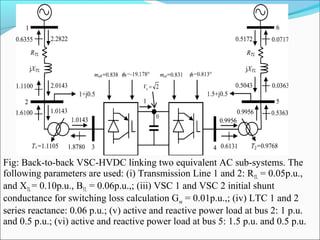
Since both converters are connected their DC side to a common DC bus
0, it should be noted that buses OR and OI are the same bus in this
back-to-back VSC-HVDC application.
61.
62. Fig: Back-to-back VSC-HVDC linking two equivalent AC sub-systems. The
following parameters are used: (i) Transmission Line 1 and 2: RTL = 0.05p.u.,
and XTL= 0.10p.u., BTL = 0.06p.u.,; (iii) VSC 1 and VSC 2 initial shunt
conductance for switching loss calculation Gsw = 0.01p.u.,; (iv) LTC 1 and 2
series reactance: 0.06 p.u.; (v) active and reactive power load at bus 2: 1 p.u.
and 0.5 p.u.; (vi) active and reactive power load at bus 5: 1.5 p.u. and 0.5 p.u.
64. SUMMARY OF POWER LOSSES INCURRED BY
THE VARIOUS MODELS
Model
Active Power
Losses(MW)
Reactive Power
losses (MVAR)
AC1 AC2 VSC-HVDC AC1 AC2 VSC-HVDC
PV buses 2641 1.29 N/A 72.95 5.13 N/A
Sources 26.58 1.28 0.57 73.27 5.19 5.74
New model 26.89 1.31 1.97 7445 5.38 5.91
65.
66. A new model suitable for VSC-HVDC links using Newton-Raphson
power flows solutions has been developed. In this model properties
of PWM , ohmic losses and conduction losses of VSCs are included.
The phase angle of the complex tap changer represents the phase
shift that would persist in a PWM inverter. More significantly, this
would be the phase angle required by the voltage source converter to
enable either reactive power generation or absorption purely by
electronic processing of the voltage and current waveforms within
the operation of voltage source converter.
Comparisons were also made against a model where the VSC-HVDC
link is represented as two PV-type nodes at its connecting nodes with
the two AC sub-systems.
67. A new VSC HVDC model has been presented and power flow has
been analysed with Newton’s Raphson method. It should be noted
that although no multi-terminal VSC-HVDC test cases are addressed
in thesis, the formulation here presented is also suitable for solving
such systems.
The natural idea of connecting dc links together to form the VSC-
HVDC system will quite possibly lead to the emergence of dc grids,
which may profoundly affect the future of the electric power grid.
The new model developed may be extended to power flow analysis
for multiple grids connected through VSC-HVDC links.