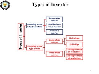
SlideShare a Scribd company logo
INVERTER
UNIT 4
INTRODUCTION TO POWER
ELECTRONICS
DEE 402
by
VINOD SHRIVASTAVA
Department of Electrical Engineering
University Polytechnic
IFTM University, Moradabad
CONTENTS
1. Introduction
2. Types of Inverter
3. Square Wave Inverter
4. Modified Sine Wave Inverter
5. Sine Wave Inverter
6. Single-phase inverter
7. Three-phase Inverter
8. IMPORTANT QUESTIONS
9. MULTIPLE CHOICE QUESTIONS
2
INTRODUCTION
What is an Inverter?
An inverter (or power inverter) is a power electronics device
which used to convert DC voltage into AC voltage.
The inverter is a static device. It can convert one form of
electrical power into other forms of electrical power. But it
cannot generate electrical power. Hence the inverter is a
converter, not a generator.
It can be used as a standalone device such as solar power or
back power for home appliances.
The inverter takes DC power from the batteries and converts
into AC power at the time of the power failure.
3
Types of Inverter
4
5
According to the Output Waveform
• There are three types of inverters.
• Square wave inverter
• Modified sine wave inverter
• Sine wave inverter
Square Wave Inverter
6
This is the least used but simplest type of inverter. The
output waveform of this inverter is a square wave. The home
appliances and most of all equipment that works on AC,
designed for the sine wave.
It converts the straight DC signal to a phase-shifting AC
signal. But the output is not a pure AC signal. This is the
cheapest type of inverter.
This inverter is also known as quasi wave inverter. This
inverter generates the signal near to the sine wave. But it
cannot generate the smooth sine wave.
The construction of this inverter is more complex than the
square wave inverter but simpler than the sine wave inverter.
7
Modified Sine Wave Inverter
Sine Wave Inverter
This is the most efficient and complex type of inverter. It
generates the pure sine wave which is a similar waveform of
the grid power. All AC equipment designed to work on the
sine wave signal.
This inverter made the least losses. But the cost of this
inverter is very high. This type of inverters is widely used in
residential and commercial applications.
8
According to the Type of Load
There are two types of AC power; single-phase and three-
phase. Therefore, there are two types of load. And according
to that, there are two types of inverters:
Single-phase inverter
Three-phase inverter
9
SINGLE-PHASE INVERTER
10
If the load is a single-phase, the inverter used to run the load
that is the single-phase inverter. There are two types;
Half-bridge inverter
Full-bridge inverter
Single-phase Half-bridge Inverter
11
Two thyristors (T1 and T2) connected with two feedback
diodes (D1 and D2) as shown in the below circuit diagram.
The supply voltage divides into two equal parts. The
resistive load used to understand the working principle.
12
Single-phase Half-bridge Inverter
Mode-1
Thyristor T1 is ON and T2 is
OFF during this mode. The
current flowing path is Vs/2-
T1-B-RL-A-Vs/2.
The current flowing through
the load is B to A direction.
And the voltage across the
load is positive Vs/2. In this
mode, the positive cycle of
the output generates.
Single-phase Half-bridge Inverter
• Mode-2
Thyristor T2 is ON and T1 is
OFF during this mode. The
current flowing path is Vs/2-A-
RL-B-T2-Vs/2.
The current flowing through
the load A to B direction. The
voltage across the load is
negative Vs/2. In this mode, the
negative cycle of output
generates.
13
Single-phase Full-bridge Inverter
In a full-bridge inverter,
four thyristors and four
feedback diodes used.
One DC source applied
to the circuit.
In a half-bridge inverter,
one switch is in
conduction at a time.
And in a full-bridge
inverter, two switches
are in conduction at a
time.
14
Single-phase Full-bridge Inverter
15
Note Here Vdc= Vs
Single-phase Full-bridge Inverter
Mode-1
 Thyristor S1 and S2
are ON and
thyristors S3 and S4
are OFF during this
mode. The current
flowing path is V-
S1-A-RL-B-S2-V.
 The current flowing
through the load is
from A to B and
make a positive half
cycle.
16
Single-phase Full-bridge Inverter
Mode-2
Thyristor S3 and S4
are ON and thyristor
S1 and S2 are OFF.
The current flowing
path is V-S3-B-RL-A-
S4-V.
The current flowing
through the load is
from B to A and make
a negative half cycle of
output.
17
Three-phase Inverter
Generally, three-phase AC supply used in industries
and the load is three-phase. In this case, a three-
phase inverter used to run this load.
18
Three-phase Inverter
In a three-phase inverter, six diodes and six
thyristors used. According to the conduction time of
thyristor, this inverter divides into two types;
• 120-degree mode of operation
• 180-degree mode of operation
19
Three-phase Inverter
120-Degree Mode of Operation
At a time, two thyristors are in conduction. The
conduction time for all thyristors is 120-degree. It
means, a switch remains ON for 120-degree and
OFF for the next 240-degree.
The shape of phase voltage is a quasi-square wave
and the shape of the line voltage is three-stepped
waveform.
20
Three-phase Inverter
21
Three-phase Inverter
180-Degree Mode of Operation
Three thyristors are in conduction at a time. The conduction time
for all thyristors is 180-degree.
The shape of the line voltage and phase voltage is opposite to the
120-degree mode of operation. Here, for phase voltage, a
waveform is a three-stepped wave and for line voltage, a
waveform is a quasi-square wave.
In a 180-degree mode of operation, two thyristors of the common
bridge are ON and OFF simultaneously. For example, in half cycle
(180-degree) S1 is ON and the next half-cycle S4 is ON. So, at the
same time, S1 is switching OFF and S4 is switching ON. Because
of this simultaneous conduction, it is possible that the source may
sort circuited.
This problem will not happen in a 120-degree mode of operation.
22
Three-phase Inverter
23
24
IMPORTANT QUESTIONS
Q.1. Explain the single phase half bridge inverter for R Load
with circuit diagram and waveforms.
Q.2. Explain the single phase full bridge inverter for R Load
with circuit diagram and waveforms.
Q.3.Explain the working principle of 3 phase bridge inverter.
Also draw the voltage waveform for 180 degree mode VSI.
Q.4. What is inverter? Explain its types according to its output
waveforms.
MULTIPLE CHOICE QUESTIONS
Q1.In a VSI (Voltage source inverter) …………………. i) the internal impedance of the DC
source is negligible ii) the internal impedance of the DC source is very very high iii) the
internal impedance of the AC source is negligible iv) the IGBTs are fired at 0 degrees
Q2. Single phase half bridge inverters requires……………………… i) two wire ac supply ii)
two wire dc supply iii) three wire ac supply iv) three wire dc supply
Q3.In the 180° mode VSI, ___________ devices conduct at a time. i) 5 ii) 2 iii) 3 iv) 4
Q4.The shape of the output voltage waveform in a single PWM is……………… i) square
wave ii) triangular wave
iii) quasi-square wave iv) sine wave
Q5.Several equidistant pulses per half cycle are used in ___________ type of modulation
technique. i) single-pulse ii) multiple-pulse iii) sine-pulse iv) equidistant-pulse
25
MULTIPLE CHOICE QUESTIONS
Q6.In ___________ type of modulation method, the pulse width is not equal for all the pulses. i) multiple
pulse width modulation ii) single pulse width modulation iii) sinusoidal pulse width modulation iv)
none of the above
Q7.In the sinusoidal pulse width modulation, __________ is the carrier wave signal. i) square wave ii)
triangular wave iii) sinusoidal wave iv) quasi-square wave
Q8. In a half wave circuit, forced commutation is essential when the
a) load is inductive b) load is resistive c) source voltage is below 150 V d) none of the mentioned
Q.9. A thyristor equivalent of a thyratron tube is a 1. Diac 2. Triac 3. Silicon controlled rectifier 4. None of
the above
Q.10. A triac is a 1. 2 terminal switch 2. 2 terminal bilateral switch 3. 3 terminal bilateral switch 4. 3
terminal bidirectional switch
26

More Related Content

What's hot

Motor drives
Motor drivesMotor drives
Motor drives
Nilesh Kulkarni
 
Pulse width modulated inverter
Pulse width modulated inverterPulse width modulated inverter
Pulse width modulated inverter
VSRAGHU
 
Single phase full bridge inverter
Single phase full bridge inverterSingle phase full bridge inverter
Single phase full bridge inverter
Nisarg Amin
 
4.inverter final
4.inverter final4.inverter final
4.inverter final
Ashu0711
 
Cycloconverters
CycloconvertersCycloconverters
Cycloconverters
Akshay Parmar
 
Power electronics Phase Controlled Rectifiers - SCR
Power electronics   Phase Controlled Rectifiers - SCRPower electronics   Phase Controlled Rectifiers - SCR
Power electronics Phase Controlled Rectifiers - SCR
Burdwan University
 
Methods of Voltage Control
Methods of Voltage ControlMethods of Voltage Control
Methods of Voltage Control
Yashvi Mehta
 
ppt on inveters
ppt on invetersppt on inveters
ppt on inveters
Urvashi Khandelwal
 
A presentation on inverter by manoj
A presentation on inverter by manojA presentation on inverter by manoj
A presentation on inverter by manoj
IACM SmartLearn Ltd.
 
Three phase voltage source inverter
Three phase voltage source inverterThree phase voltage source inverter
Three phase voltage source inverter
tamilnesaner
 
IGBT
IGBTIGBT
Sinusoidal pwm
Sinusoidal pwmSinusoidal pwm
Sinusoidal pwm
Chintan Hansalia
 
VSC based HVDC system
VSC based HVDC systemVSC based HVDC system
VSC based HVDC system
mdhsudhan
 
Electrical ac & dc drives ppt
Electrical ac & dc drives pptElectrical ac & dc drives ppt
Electrical ac & dc drives ppt
chakri218
 
Unit 2.Converter and Chopper fed Dc drives
Unit 2.Converter and Chopper fed Dc drivesUnit 2.Converter and Chopper fed Dc drives
Unit 2.Converter and Chopper fed Dc drives
raviarmugam
 
Scr firing circuits
Scr firing circuitsScr firing circuits
Scr firing circuits
Vinod Srivastava
 
Three phase inverter - 180 and 120 Degree Mode of Conduction
Three phase inverter - 180 and 120 Degree Mode of ConductionThree phase inverter - 180 and 120 Degree Mode of Conduction
Three phase inverter - 180 and 120 Degree Mode of Conduction
MalarselvamV
 
dc to dc-converter
dc to dc-converterdc to dc-converter
dc to dc-converter
Student
 
Single phase ac voltage controller
Single phase ac voltage controllerSingle phase ac voltage controller
Single phase ac voltage controller
Swati Tiwari
 

What's hot (20)

Motor drives
Motor drivesMotor drives
Motor drives
 
Pulse width modulated inverter
Pulse width modulated inverterPulse width modulated inverter
Pulse width modulated inverter
 
Single phase full bridge inverter
Single phase full bridge inverterSingle phase full bridge inverter
Single phase full bridge inverter
 
4.inverter final
4.inverter final4.inverter final
4.inverter final
 
Cycloconverters
CycloconvertersCycloconverters
Cycloconverters
 
Power electronics Phase Controlled Rectifiers - SCR
Power electronics   Phase Controlled Rectifiers - SCRPower electronics   Phase Controlled Rectifiers - SCR
Power electronics Phase Controlled Rectifiers - SCR
 
Methods of Voltage Control
Methods of Voltage ControlMethods of Voltage Control
Methods of Voltage Control
 
ppt on inveters
ppt on invetersppt on inveters
ppt on inveters
 
A presentation on inverter by manoj
A presentation on inverter by manojA presentation on inverter by manoj
A presentation on inverter by manoj
 
Three phase voltage source inverter
Three phase voltage source inverterThree phase voltage source inverter
Three phase voltage source inverter
 
IGBT
IGBTIGBT
IGBT
 
Sinusoidal pwm
Sinusoidal pwmSinusoidal pwm
Sinusoidal pwm
 
VSC based HVDC system
VSC based HVDC systemVSC based HVDC system
VSC based HVDC system
 
Electrical ac & dc drives ppt
Electrical ac & dc drives pptElectrical ac & dc drives ppt
Electrical ac & dc drives ppt
 
Unit 2.Converter and Chopper fed Dc drives
Unit 2.Converter and Chopper fed Dc drivesUnit 2.Converter and Chopper fed Dc drives
Unit 2.Converter and Chopper fed Dc drives
 
Circuit breaker
Circuit breakerCircuit breaker
Circuit breaker
 
Scr firing circuits
Scr firing circuitsScr firing circuits
Scr firing circuits
 
Three phase inverter - 180 and 120 Degree Mode of Conduction
Three phase inverter - 180 and 120 Degree Mode of ConductionThree phase inverter - 180 and 120 Degree Mode of Conduction
Three phase inverter - 180 and 120 Degree Mode of Conduction
 
dc to dc-converter
dc to dc-converterdc to dc-converter
dc to dc-converter
 
Single phase ac voltage controller
Single phase ac voltage controllerSingle phase ac voltage controller
Single phase ac voltage controller
 

Similar to Inverter

Kartar power ppt
Kartar power pptKartar power ppt
Kartar power ppt
Kartar Jamwal
 
Inverter
InverterInverter
Inverter
Zamir Fatemi
 
Inverter PPT.ppt
Inverter PPT.pptInverter PPT.ppt
Inverter PPT.ppt
AbhishekRanjan17318
 
PE UNIT IV - INVERTERS.pptx
PE UNIT IV - INVERTERS.pptxPE UNIT IV - INVERTERS.pptx
PE UNIT IV - INVERTERS.pptx
MuthuKumar158260
 
Cyclo converters
Cyclo convertersCyclo converters
Cyclo converters
Jaya Shree
 
PE UNIT IV.pptx
PE UNIT IV.pptxPE UNIT IV.pptx
PE UNIT IV.pptx
Karthik Kathan
 
Shivam k11915
Shivam k11915Shivam k11915
Shivam k11915
Shivam Kumar
 
Untitled document.PDF
Untitled document.PDFUntitled document.PDF
Untitled document.PDF
AshishRana497089
 
Rectifier
RectifierRectifier
Rectifier
vishalgohel12195
 
IRJET- A Dual Stage Flyback Converter using VC Method
IRJET- A Dual Stage Flyback Converter using VC MethodIRJET- A Dual Stage Flyback Converter using VC Method
IRJET- A Dual Stage Flyback Converter using VC Method
IRJET Journal
 
LIC UNIT V.pptx
LIC UNIT V.pptxLIC UNIT V.pptx
LIC UNIT V.pptx
ArunS118525
 
Chapter 5 - DC-AC Conversion.pdf
Chapter 5 - DC-AC Conversion.pdfChapter 5 - DC-AC Conversion.pdf
Chapter 5 - DC-AC Conversion.pdf
benson215
 
PED drivers t5656979089897877ghvvnvgcxxn
PED drivers t5656979089897877ghvvnvgcxxnPED drivers t5656979089897877ghvvnvgcxxn
PED drivers t5656979089897877ghvvnvgcxxn
nightbot15
 
Unit iv inverters
Unit iv invertersUnit iv inverters
Unit iv inverters
WisdomMahami
 
Power Electronics 2 mark Questions
Power Electronics 2 mark Questions Power Electronics 2 mark Questions
Power Electronics 2 mark Questions
BALACHANDRAN D
 
Cycloconverters
CycloconvertersCycloconverters
Cycloconverters
Vishal_popat
 
Synchmachine
SynchmachineSynchmachine
Synchmachine
Engineer Noman Shahid
 
Presentation1
Presentation1Presentation1
Presentation1
Bhismadev Patel
 
Full Wave Bridge Rectifier.pptx
Full Wave Bridge Rectifier.pptxFull Wave Bridge Rectifier.pptx
Full Wave Bridge Rectifier.pptx
RituSachan2
 

Similar to Inverter (20)

Kartar power ppt
Kartar power pptKartar power ppt
Kartar power ppt
 
Inverter
InverterInverter
Inverter
 
Inverter PPT.ppt
Inverter PPT.pptInverter PPT.ppt
Inverter PPT.ppt
 
PE UNIT IV - INVERTERS.pptx
PE UNIT IV - INVERTERS.pptxPE UNIT IV - INVERTERS.pptx
PE UNIT IV - INVERTERS.pptx
 
Cyclo converters
Cyclo convertersCyclo converters
Cyclo converters
 
PE UNIT IV.pptx
PE UNIT IV.pptxPE UNIT IV.pptx
PE UNIT IV.pptx
 
Shivam k11915
Shivam k11915Shivam k11915
Shivam k11915
 
Untitled document.PDF
Untitled document.PDFUntitled document.PDF
Untitled document.PDF
 
power-electronics
power-electronicspower-electronics
power-electronics
 
Rectifier
RectifierRectifier
Rectifier
 
IRJET- A Dual Stage Flyback Converter using VC Method
IRJET- A Dual Stage Flyback Converter using VC MethodIRJET- A Dual Stage Flyback Converter using VC Method
IRJET- A Dual Stage Flyback Converter using VC Method
 
LIC UNIT V.pptx
LIC UNIT V.pptxLIC UNIT V.pptx
LIC UNIT V.pptx
 
Chapter 5 - DC-AC Conversion.pdf
Chapter 5 - DC-AC Conversion.pdfChapter 5 - DC-AC Conversion.pdf
Chapter 5 - DC-AC Conversion.pdf
 
PED drivers t5656979089897877ghvvnvgcxxn
PED drivers t5656979089897877ghvvnvgcxxnPED drivers t5656979089897877ghvvnvgcxxn
PED drivers t5656979089897877ghvvnvgcxxn
 
Unit iv inverters
Unit iv invertersUnit iv inverters
Unit iv inverters
 
Power Electronics 2 mark Questions
Power Electronics 2 mark Questions Power Electronics 2 mark Questions
Power Electronics 2 mark Questions
 
Cycloconverters
CycloconvertersCycloconverters
Cycloconverters
 
Synchmachine
SynchmachineSynchmachine
Synchmachine
 
Presentation1
Presentation1Presentation1
Presentation1
 
Full Wave Bridge Rectifier.pptx
Full Wave Bridge Rectifier.pptxFull Wave Bridge Rectifier.pptx
Full Wave Bridge Rectifier.pptx
 

More from Vinod Srivastava

Hydro power plant
Hydro power plantHydro power plant
Hydro power plant
Vinod Srivastava
 
Thermal power plant
Thermal power plantThermal power plant
Thermal power plant
Vinod Srivastava
 
Thyristor commutation techniques
Thyristor commutation techniquesThyristor commutation techniques
Thyristor commutation techniques
Vinod Srivastava
 
Thyristor
ThyristorThyristor
Thyristor
Vinod Srivastava
 
Thyristor family
Thyristor familyThyristor family
Thyristor family
Vinod Srivastava
 
Faults on Power System
Faults on Power SystemFaults on Power System
Faults on Power System
Vinod Srivastava
 
Neutral grounding
Neutral groundingNeutral grounding
Neutral grounding
Vinod Srivastava
 
Line reactor
Line reactorLine reactor
Line reactor
Vinod Srivastava
 
Seminar on visa
Seminar on visaSeminar on visa
Seminar on visa
Vinod Srivastava
 
Fibre optics
Fibre opticsFibre optics
Fibre optics
Vinod Srivastava
 
Facts devices
Facts devicesFacts devices
Facts devices
Vinod Srivastava
 
Waste water sampling and analysis
Waste water sampling and analysisWaste water sampling and analysis
Waste water sampling and analysis
Vinod Srivastava
 
Embedded system
Embedded systemEmbedded system
Embedded system
Vinod Srivastava
 
Tidal energy
Tidal energyTidal energy
Tidal energy
Vinod Srivastava
 
Eigenvalues and Eigenvectors
Eigenvalues and EigenvectorsEigenvalues and Eigenvectors
Eigenvalues and Eigenvectors
Vinod Srivastava
 
Single Phase Converter
Single Phase ConverterSingle Phase Converter
Single Phase Converter
Vinod Srivastava
 

More from Vinod Srivastava (16)

Hydro power plant
Hydro power plantHydro power plant
Hydro power plant
 
Thermal power plant
Thermal power plantThermal power plant
Thermal power plant
 
Thyristor commutation techniques
Thyristor commutation techniquesThyristor commutation techniques
Thyristor commutation techniques
 
Thyristor
ThyristorThyristor
Thyristor
 
Thyristor family
Thyristor familyThyristor family
Thyristor family
 
Faults on Power System
Faults on Power SystemFaults on Power System
Faults on Power System
 
Neutral grounding
Neutral groundingNeutral grounding
Neutral grounding
 
Line reactor
Line reactorLine reactor
Line reactor
 
Seminar on visa
Seminar on visaSeminar on visa
Seminar on visa
 
Fibre optics
Fibre opticsFibre optics
Fibre optics
 
Facts devices
Facts devicesFacts devices
Facts devices
 
Waste water sampling and analysis
Waste water sampling and analysisWaste water sampling and analysis
Waste water sampling and analysis
 
Embedded system
Embedded systemEmbedded system
Embedded system
 
Tidal energy
Tidal energyTidal energy
Tidal energy
 
Eigenvalues and Eigenvectors
Eigenvalues and EigenvectorsEigenvalues and Eigenvectors
Eigenvalues and Eigenvectors
 
Single Phase Converter
Single Phase ConverterSingle Phase Converter
Single Phase Converter
 

Recently uploaded

Democratizing Fuzzing at Scale by Abhishek Arya
Democratizing Fuzzing at Scale by Abhishek AryaDemocratizing Fuzzing at Scale by Abhishek Arya
Democratizing Fuzzing at Scale by Abhishek Arya
abh.arya
 
weather web application report.pdf
weather web application report.pdfweather web application report.pdf
weather web application report.pdf
Pratik Pawar
 
Pile Foundation by Venkatesh Taduvai (Sub Geotechnical Engineering II)-conver...
Pile Foundation by Venkatesh Taduvai (Sub Geotechnical Engineering II)-conver...Pile Foundation by Venkatesh Taduvai (Sub Geotechnical Engineering II)-conver...
Pile Foundation by Venkatesh Taduvai (Sub Geotechnical Engineering II)-conver...
AJAYKUMARPUND1
 
block diagram and signal flow graph representation
block diagram and signal flow graph representationblock diagram and signal flow graph representation
block diagram and signal flow graph representation
Divya Somashekar
 
Student information management system project report ii.pdf
Student information management system project report ii.pdfStudent information management system project report ii.pdf
Student information management system project report ii.pdf
Kamal Acharya
 
Forklift Classes Overview by Intella Parts
Forklift Classes Overview by Intella PartsForklift Classes Overview by Intella Parts
Forklift Classes Overview by Intella Parts
Intella Parts
 
addressing modes in computer architecture
addressing modes  in computer architectureaddressing modes  in computer architecture
addressing modes in computer architecture
ShahidSultan24
 
Top 10 Oil and Gas Projects in Saudi Arabia 2024.pdf
Top 10 Oil and Gas Projects in Saudi Arabia 2024.pdfTop 10 Oil and Gas Projects in Saudi Arabia 2024.pdf
Top 10 Oil and Gas Projects in Saudi Arabia 2024.pdf
Teleport Manpower Consultant
 
Hybrid optimization of pumped hydro system and solar- Engr. Abdul-Azeez.pdf
Hybrid optimization of pumped hydro system and solar- Engr. Abdul-Azeez.pdfHybrid optimization of pumped hydro system and solar- Engr. Abdul-Azeez.pdf
Hybrid optimization of pumped hydro system and solar- Engr. Abdul-Azeez.pdf
fxintegritypublishin
 
CME397 Surface Engineering- Professional Elective
CME397 Surface Engineering- Professional ElectiveCME397 Surface Engineering- Professional Elective
CME397 Surface Engineering- Professional Elective
karthi keyan
 
Quality defects in TMT Bars, Possible causes and Potential Solutions.
Quality defects in TMT Bars, Possible causes and Potential Solutions.Quality defects in TMT Bars, Possible causes and Potential Solutions.
Quality defects in TMT Bars, Possible causes and Potential Solutions.
PrashantGoswami42
 
COLLEGE BUS MANAGEMENT SYSTEM PROJECT REPORT.pdf
COLLEGE BUS MANAGEMENT SYSTEM PROJECT REPORT.pdfCOLLEGE BUS MANAGEMENT SYSTEM PROJECT REPORT.pdf
COLLEGE BUS MANAGEMENT SYSTEM PROJECT REPORT.pdf
Kamal Acharya
 
Cosmetic shop management system project report.pdf
Cosmetic shop management system project report.pdfCosmetic shop management system project report.pdf
Cosmetic shop management system project report.pdf
Kamal Acharya
 
CFD Simulation of By-pass Flow in a HRSG module by R&R Consult.pptx
CFD Simulation of By-pass Flow in a HRSG module by R&R Consult.pptxCFD Simulation of By-pass Flow in a HRSG module by R&R Consult.pptx
CFD Simulation of By-pass Flow in a HRSG module by R&R Consult.pptx
R&R Consult
 
Gen AI Study Jams _ For the GDSC Leads in India.pdf
Gen AI Study Jams _ For the GDSC Leads in India.pdfGen AI Study Jams _ For the GDSC Leads in India.pdf
Gen AI Study Jams _ For the GDSC Leads in India.pdf
gdsczhcet
 
The Benefits and Techniques of Trenchless Pipe Repair.pdf
The Benefits and Techniques of Trenchless Pipe Repair.pdfThe Benefits and Techniques of Trenchless Pipe Repair.pdf
The Benefits and Techniques of Trenchless Pipe Repair.pdf
Pipe Restoration Solutions
 
Design and Analysis of Algorithms-DP,Backtracking,Graphs,B&B
Design and Analysis of Algorithms-DP,Backtracking,Graphs,B&BDesign and Analysis of Algorithms-DP,Backtracking,Graphs,B&B
Design and Analysis of Algorithms-DP,Backtracking,Graphs,B&B
Sreedhar Chowdam
 
DESIGN A COTTON SEED SEPARATION MACHINE.docx
DESIGN A COTTON SEED SEPARATION MACHINE.docxDESIGN A COTTON SEED SEPARATION MACHINE.docx
DESIGN A COTTON SEED SEPARATION MACHINE.docx
FluxPrime1
 
Automobile Management System Project Report.pdf
Automobile Management System Project Report.pdfAutomobile Management System Project Report.pdf
Automobile Management System Project Report.pdf
Kamal Acharya
 
ethical hacking in wireless-hacking1.ppt
ethical hacking in wireless-hacking1.pptethical hacking in wireless-hacking1.ppt
ethical hacking in wireless-hacking1.ppt
Jayaprasanna4
 

Recently uploaded (20)

Democratizing Fuzzing at Scale by Abhishek Arya
Democratizing Fuzzing at Scale by Abhishek AryaDemocratizing Fuzzing at Scale by Abhishek Arya
Democratizing Fuzzing at Scale by Abhishek Arya
 
weather web application report.pdf
weather web application report.pdfweather web application report.pdf
weather web application report.pdf
 
Pile Foundation by Venkatesh Taduvai (Sub Geotechnical Engineering II)-conver...
Pile Foundation by Venkatesh Taduvai (Sub Geotechnical Engineering II)-conver...Pile Foundation by Venkatesh Taduvai (Sub Geotechnical Engineering II)-conver...
Pile Foundation by Venkatesh Taduvai (Sub Geotechnical Engineering II)-conver...
 
block diagram and signal flow graph representation
block diagram and signal flow graph representationblock diagram and signal flow graph representation
block diagram and signal flow graph representation
 
Student information management system project report ii.pdf
Student information management system project report ii.pdfStudent information management system project report ii.pdf
Student information management system project report ii.pdf
 
Forklift Classes Overview by Intella Parts
Forklift Classes Overview by Intella PartsForklift Classes Overview by Intella Parts
Forklift Classes Overview by Intella Parts
 
addressing modes in computer architecture
addressing modes  in computer architectureaddressing modes  in computer architecture
addressing modes in computer architecture
 
Top 10 Oil and Gas Projects in Saudi Arabia 2024.pdf
Top 10 Oil and Gas Projects in Saudi Arabia 2024.pdfTop 10 Oil and Gas Projects in Saudi Arabia 2024.pdf
Top 10 Oil and Gas Projects in Saudi Arabia 2024.pdf
 
Hybrid optimization of pumped hydro system and solar- Engr. Abdul-Azeez.pdf
Hybrid optimization of pumped hydro system and solar- Engr. Abdul-Azeez.pdfHybrid optimization of pumped hydro system and solar- Engr. Abdul-Azeez.pdf
Hybrid optimization of pumped hydro system and solar- Engr. Abdul-Azeez.pdf
 
CME397 Surface Engineering- Professional Elective
CME397 Surface Engineering- Professional ElectiveCME397 Surface Engineering- Professional Elective
CME397 Surface Engineering- Professional Elective
 
Quality defects in TMT Bars, Possible causes and Potential Solutions.
Quality defects in TMT Bars, Possible causes and Potential Solutions.Quality defects in TMT Bars, Possible causes and Potential Solutions.
Quality defects in TMT Bars, Possible causes and Potential Solutions.
 
COLLEGE BUS MANAGEMENT SYSTEM PROJECT REPORT.pdf
COLLEGE BUS MANAGEMENT SYSTEM PROJECT REPORT.pdfCOLLEGE BUS MANAGEMENT SYSTEM PROJECT REPORT.pdf
COLLEGE BUS MANAGEMENT SYSTEM PROJECT REPORT.pdf
 
Cosmetic shop management system project report.pdf
Cosmetic shop management system project report.pdfCosmetic shop management system project report.pdf
Cosmetic shop management system project report.pdf
 
CFD Simulation of By-pass Flow in a HRSG module by R&R Consult.pptx
CFD Simulation of By-pass Flow in a HRSG module by R&R Consult.pptxCFD Simulation of By-pass Flow in a HRSG module by R&R Consult.pptx
CFD Simulation of By-pass Flow in a HRSG module by R&R Consult.pptx
 
Gen AI Study Jams _ For the GDSC Leads in India.pdf
Gen AI Study Jams _ For the GDSC Leads in India.pdfGen AI Study Jams _ For the GDSC Leads in India.pdf
Gen AI Study Jams _ For the GDSC Leads in India.pdf
 
The Benefits and Techniques of Trenchless Pipe Repair.pdf
The Benefits and Techniques of Trenchless Pipe Repair.pdfThe Benefits and Techniques of Trenchless Pipe Repair.pdf
The Benefits and Techniques of Trenchless Pipe Repair.pdf
 
Design and Analysis of Algorithms-DP,Backtracking,Graphs,B&B
Design and Analysis of Algorithms-DP,Backtracking,Graphs,B&BDesign and Analysis of Algorithms-DP,Backtracking,Graphs,B&B
Design and Analysis of Algorithms-DP,Backtracking,Graphs,B&B
 
DESIGN A COTTON SEED SEPARATION MACHINE.docx
DESIGN A COTTON SEED SEPARATION MACHINE.docxDESIGN A COTTON SEED SEPARATION MACHINE.docx
DESIGN A COTTON SEED SEPARATION MACHINE.docx
 
Automobile Management System Project Report.pdf
Automobile Management System Project Report.pdfAutomobile Management System Project Report.pdf
Automobile Management System Project Report.pdf
 
ethical hacking in wireless-hacking1.ppt
ethical hacking in wireless-hacking1.pptethical hacking in wireless-hacking1.ppt
ethical hacking in wireless-hacking1.ppt
 

Inverter

  • 1. INVERTER UNIT 4 INTRODUCTION TO POWER ELECTRONICS DEE 402 by VINOD SHRIVASTAVA Department of Electrical Engineering University Polytechnic IFTM University, Moradabad
  • 2. CONTENTS 1. Introduction 2. Types of Inverter 3. Square Wave Inverter 4. Modified Sine Wave Inverter 5. Sine Wave Inverter 6. Single-phase inverter 7. Three-phase Inverter 8. IMPORTANT QUESTIONS 9. MULTIPLE CHOICE QUESTIONS 2
  • 3. INTRODUCTION What is an Inverter? An inverter (or power inverter) is a power electronics device which used to convert DC voltage into AC voltage. The inverter is a static device. It can convert one form of electrical power into other forms of electrical power. But it cannot generate electrical power. Hence the inverter is a converter, not a generator. It can be used as a standalone device such as solar power or back power for home appliances. The inverter takes DC power from the batteries and converts into AC power at the time of the power failure. 3
  • 5. 5 According to the Output Waveform • There are three types of inverters. • Square wave inverter • Modified sine wave inverter • Sine wave inverter
  • 6. Square Wave Inverter 6 This is the least used but simplest type of inverter. The output waveform of this inverter is a square wave. The home appliances and most of all equipment that works on AC, designed for the sine wave. It converts the straight DC signal to a phase-shifting AC signal. But the output is not a pure AC signal. This is the cheapest type of inverter.
  • 7. This inverter is also known as quasi wave inverter. This inverter generates the signal near to the sine wave. But it cannot generate the smooth sine wave. The construction of this inverter is more complex than the square wave inverter but simpler than the sine wave inverter. 7 Modified Sine Wave Inverter
  • 8. Sine Wave Inverter This is the most efficient and complex type of inverter. It generates the pure sine wave which is a similar waveform of the grid power. All AC equipment designed to work on the sine wave signal. This inverter made the least losses. But the cost of this inverter is very high. This type of inverters is widely used in residential and commercial applications. 8
  • 9. According to the Type of Load There are two types of AC power; single-phase and three- phase. Therefore, there are two types of load. And according to that, there are two types of inverters: Single-phase inverter Three-phase inverter 9
  • 10. SINGLE-PHASE INVERTER 10 If the load is a single-phase, the inverter used to run the load that is the single-phase inverter. There are two types; Half-bridge inverter Full-bridge inverter
  • 11. Single-phase Half-bridge Inverter 11 Two thyristors (T1 and T2) connected with two feedback diodes (D1 and D2) as shown in the below circuit diagram. The supply voltage divides into two equal parts. The resistive load used to understand the working principle.
  • 12. 12 Single-phase Half-bridge Inverter Mode-1 Thyristor T1 is ON and T2 is OFF during this mode. The current flowing path is Vs/2- T1-B-RL-A-Vs/2. The current flowing through the load is B to A direction. And the voltage across the load is positive Vs/2. In this mode, the positive cycle of the output generates.
  • 13. Single-phase Half-bridge Inverter • Mode-2 Thyristor T2 is ON and T1 is OFF during this mode. The current flowing path is Vs/2-A- RL-B-T2-Vs/2. The current flowing through the load A to B direction. The voltage across the load is negative Vs/2. In this mode, the negative cycle of output generates. 13
  • 14. Single-phase Full-bridge Inverter In a full-bridge inverter, four thyristors and four feedback diodes used. One DC source applied to the circuit. In a half-bridge inverter, one switch is in conduction at a time. And in a full-bridge inverter, two switches are in conduction at a time. 14
  • 16. Single-phase Full-bridge Inverter Mode-1  Thyristor S1 and S2 are ON and thyristors S3 and S4 are OFF during this mode. The current flowing path is V- S1-A-RL-B-S2-V.  The current flowing through the load is from A to B and make a positive half cycle. 16
  • 17. Single-phase Full-bridge Inverter Mode-2 Thyristor S3 and S4 are ON and thyristor S1 and S2 are OFF. The current flowing path is V-S3-B-RL-A- S4-V. The current flowing through the load is from B to A and make a negative half cycle of output. 17
  • 18. Three-phase Inverter Generally, three-phase AC supply used in industries and the load is three-phase. In this case, a three- phase inverter used to run this load. 18
  • 19. Three-phase Inverter In a three-phase inverter, six diodes and six thyristors used. According to the conduction time of thyristor, this inverter divides into two types; • 120-degree mode of operation • 180-degree mode of operation 19
  • 20. Three-phase Inverter 120-Degree Mode of Operation At a time, two thyristors are in conduction. The conduction time for all thyristors is 120-degree. It means, a switch remains ON for 120-degree and OFF for the next 240-degree. The shape of phase voltage is a quasi-square wave and the shape of the line voltage is three-stepped waveform. 20
  • 22. Three-phase Inverter 180-Degree Mode of Operation Three thyristors are in conduction at a time. The conduction time for all thyristors is 180-degree. The shape of the line voltage and phase voltage is opposite to the 120-degree mode of operation. Here, for phase voltage, a waveform is a three-stepped wave and for line voltage, a waveform is a quasi-square wave. In a 180-degree mode of operation, two thyristors of the common bridge are ON and OFF simultaneously. For example, in half cycle (180-degree) S1 is ON and the next half-cycle S4 is ON. So, at the same time, S1 is switching OFF and S4 is switching ON. Because of this simultaneous conduction, it is possible that the source may sort circuited. This problem will not happen in a 120-degree mode of operation. 22
  • 24. 24 IMPORTANT QUESTIONS Q.1. Explain the single phase half bridge inverter for R Load with circuit diagram and waveforms. Q.2. Explain the single phase full bridge inverter for R Load with circuit diagram and waveforms. Q.3.Explain the working principle of 3 phase bridge inverter. Also draw the voltage waveform for 180 degree mode VSI. Q.4. What is inverter? Explain its types according to its output waveforms.
  • 25. MULTIPLE CHOICE QUESTIONS Q1.In a VSI (Voltage source inverter) …………………. i) the internal impedance of the DC source is negligible ii) the internal impedance of the DC source is very very high iii) the internal impedance of the AC source is negligible iv) the IGBTs are fired at 0 degrees Q2. Single phase half bridge inverters requires……………………… i) two wire ac supply ii) two wire dc supply iii) three wire ac supply iv) three wire dc supply Q3.In the 180° mode VSI, ___________ devices conduct at a time. i) 5 ii) 2 iii) 3 iv) 4 Q4.The shape of the output voltage waveform in a single PWM is……………… i) square wave ii) triangular wave iii) quasi-square wave iv) sine wave Q5.Several equidistant pulses per half cycle are used in ___________ type of modulation technique. i) single-pulse ii) multiple-pulse iii) sine-pulse iv) equidistant-pulse 25
  • 26. MULTIPLE CHOICE QUESTIONS Q6.In ___________ type of modulation method, the pulse width is not equal for all the pulses. i) multiple pulse width modulation ii) single pulse width modulation iii) sinusoidal pulse width modulation iv) none of the above Q7.In the sinusoidal pulse width modulation, __________ is the carrier wave signal. i) square wave ii) triangular wave iii) sinusoidal wave iv) quasi-square wave Q8. In a half wave circuit, forced commutation is essential when the a) load is inductive b) load is resistive c) source voltage is below 150 V d) none of the mentioned Q.9. A thyristor equivalent of a thyratron tube is a 1. Diac 2. Triac 3. Silicon controlled rectifier 4. None of the above Q.10. A triac is a 1. 2 terminal switch 2. 2 terminal bilateral switch 3. 3 terminal bilateral switch 4. 3 terminal bidirectional switch 26