Downloaded 1,793 times
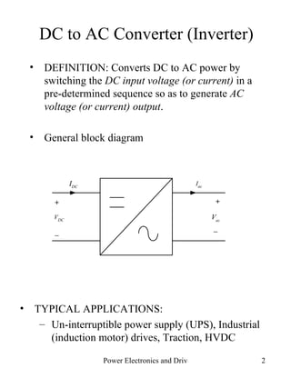


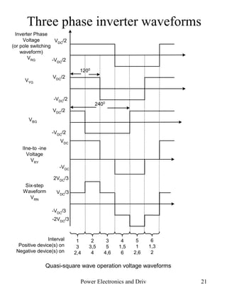


The document discusses DC to AC conversion using inverters. It describes the basic concept and components of inverters including single-phase, full-bridge, and three-phase inverter topologies. It also covers modulation techniques such as pulse width modulation (PWM) and discusses how they affect the output waveform harmonics.


