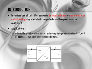
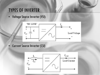
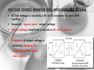
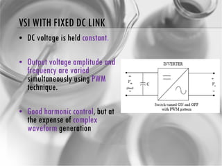
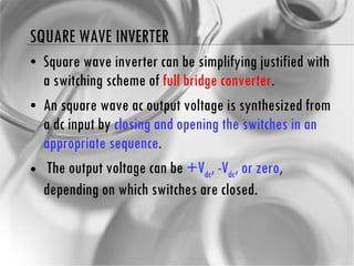
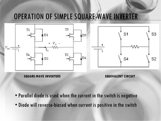
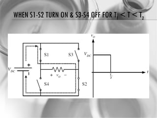
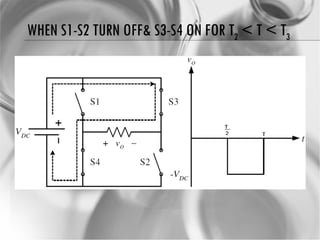
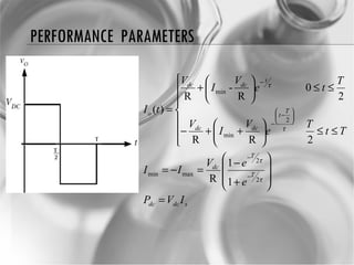
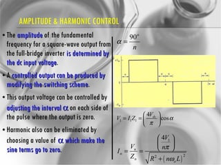
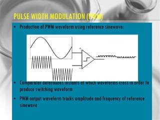
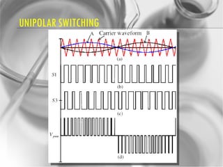
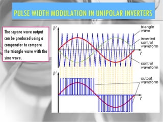
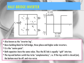
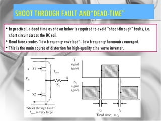
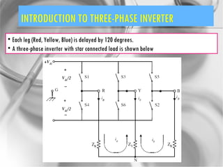
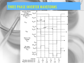
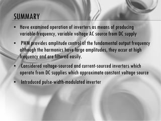
DC TO AC CONVERTER Mohd Shawal Bin Jadin Faculty of Electrical & Electronic Engineering [email_address] BEE4223  Power Electronics & Drives Systems
OVERVIEW Introduction  Principle of operation Performance parameter The half-bridge inverter  Pulse Width Modulation (PWM) PWM Generation PWM Harmonics Current Source Inverter Introduction to three-phase inverter Conclusions
LEARNING OUTCOMES At the end of the lecture, student should be able to: State the operation and characteristics of Inverter.  Discuss the performance parameters and use different technique for analyzing and designing of DC to AC Converter.
INTRODUCTION Inverters are circuits that converts  dc input voltage  to  a symmetric ac output voltage  by which both magnitude and frequency can be controlled. Applications : adjustable speed ac motor drives,  uninterruptible  power supplies (UPS), and ac appliances run from an automobile battery.
TYPES OF INVERTER Voltage Source Inverter (VSI): Current Source Inverter (CSI)
VOLTAGE SOURCE INVERTER (VSI) WITH VARIABLE DC LINK DC link voltage is varied by a DC-to DC converter or controlled rectifier. Generate  “ square wave ”  output voltage. Output voltage  amplitude is varied as  DC link is varied . Frequency  of output voltage is varied by  changing the  frequency of   the square  wave pulses .
VOLTAGE SOURCE INVERTER (VSI) WITH VARIABLE DC LINK Advantages: simple waveform generation Reliable Disadvantages: Extra conversion stage Poor harmonics
VSI WITH FIXED DC LINK DC voltage is held  constant . Output voltage amplitude and frequency are varied  simultaneously using  PWM  technique. Good harmonic control , but at the expense of  complex waveform  generation
SQUARE WAVE INVERTER Square wave inverter can be simplifying justified with a switching scheme of  full bridge converter . An square wave ac output voltage is synthesized from a dc input by  closing and opening the switches in an appropriate sequence . The output voltage can be  +V dc , -V dc , or zero , depending on which switches are closed.
OPERATION OF SIMPLE SQUARE-WAVE INVERTER  Parallel diode is used when the current in the switch is negative Diode will reverse-biased when current is positive in the switch SQUARE-WAVE INVERTERS EQUIVALENT CIRCUIT
WHEN S1-S2 TURN ON & S3-S4 OFF FOR T 1  < T < T 2
WHEN S1-S2 TURN OFF& S3-S4 ON FOR T 2  < T < T 3
PERFORMANCE  PARAMETERS
EXAMPLE A square-wave inverter has a dc source of 125V, an output frequency of 60 Hz, and R-L series load with R = 20 Ohm and L = 20 mH. Determine An expression for load current Rms load current and Average source current
FOURIER SERIES ANALYSIS FOR SQUARE WAVE INVERTER Fourier series method is often the most practical way to analyze load current and to compute power absorbed by load.
FOURIER SERIES ANALYSIS FOR SQUARE WAVE INVERTER The quality of ac output voltage or current can be expressed by total Harmonic Distortion (THD)
EXAMPLE 1 Consider a square wave inverter with V dc =100V, R=10  , L=25mH, and  f =60Hz. Determine Fundamental output voltage THD for output voltage and current and power absorbed by load
EXAMPLE 2 Fundamental output voltage THD v  and THD I
EXAMPLE 2 n f n  (Hz) V n  (V) Z n  (  ) I n  (A) P n  (W) 1 60 127.3 13.7 9.27 429.3 3 180 42.3 30 1.42 10 5 300 25.5 48.2 0.53 1.4 7 420 18.2 66.7 0.27 0.37 9 540 14.1 85.4 0.17 0.14
EXAMPLE 1 (CONT)
AMPLITUDE & HARMONIC CONTROL The  amplitude  of the fundamental frequency for a square-wave output from the full-bridge inverter  is determined by the dc input voltage .  A  controlled output can be produced by modifying the switching scheme .  This output voltage can be controlled by  adjusting the interval    on each side of the pulse where the output is zero. Harmonic also can be eliminated by choosing a value of    which make the sine terms go to zero.
EXAMPLE 2 Design an inverter that will supply the series R-L load of R=10  , L=25mH with a fundamental frequency of 60Hz and current amplitude of 9.27A and THD less than 10%. A variable source is available.
EXAMPLE 2 (CONT) The dominant harmonic current is for n = 3 (third harmonic), so the switching scheme must eliminate the third harmonic.
EXAMPLE 1 (CONT)
EXAMPLE 1 (CONT) n f n  (Hz) V n  (V) Z n  (  ) I n  (A) 1 60 127.3 13.7 9.27 3 180 0 30 0 5 300 25.5 48.2 0.53 7 420 18.2 66.7 0.27 9 540 0 85.4 0
TRY THIS………   –  Ω    α  
PULSE-WIDTH MODULATED OUTPUT  In square wave inverters,  maximum output voltage is achievable . However there in  NO control in harmonics and output voltage magnitude . i.e the  harmonics are always at three, five, seven etc times the fundamental frequency . Hence the  cut-off frequency of the low pass filter is somewhat fixed . The filter size is dictated by the VA ratings of the inverter. To reduce filter size, the PWM switching scheme can be utilized . In this technique,  the harmonics are “pushed” to higher frequencies . Thus the  cut-off frequency of the filter is increased.  Hence the filter components (i.e. L and C) sizes are reduced.  The trade off for this flexibility is  complexity in the switching waveforms .
PULSE WIDTH MODULATION (PWM)
PULSE WIDTH MODULATION (PWM) Triangulation method (Natural sampling) Amplitudes of the triangular wave (carrier) and sine wave (modulating) are compared to obtain PWM waveform. Simple analogue comparator can be used. Basically an analogue method. Its digital version, known as REGULAR sampling is widely used in industry.
PULSE WIDTH MODULATION (PWM) Production of PWM waveform using reference sinewave: Comparator determines instants at which waveforms cross in order to produce switching waveform PWM output waveform tracks amplitude and frequency of reference sinewave
PULSE WIDTH MODULATION (PWM) As switching frequency is increased, switching loss becomes issue Implementation by ICs which essentially contain tables of pre-calculated values of switching angles covering range of output frequencies As computational speeds of ICs increase, it is now possible to calculate required firing angles in real time in order to optimise strategy for harmonic elimination, and control, further improving inverter performance
PULSE WIDTH MODULATION (PWM) TYPES Natural (sinusoidal) sampling  (as shown on previous slide) Problems with analogue circuitry, e.g. Drift, sensitivity etc. Regular sampling  -  simplified version of natural sampling that results in simple digital implementation Optimised PWM  -  PWM waveform are constructed based on certain performance criteria, e.g. THD. Harmonic elimination/minimisation PWM PWM waveforms are constructed to eliminate some undesirable harmonics from the output waveform spectra. Highly mathematical in nature Space-vector modulation (SVM) A simple technique based on volt-second that is normally used with three-phase inverter motordrive
BIPOLAR SWITCHING
UNIPOLAR SWITCHING
PULSE WIDTH MODULATION IN UNIPOLAR INVERTERS The square wave output can be produced using a comparator to compare the triangle wave with the sine wave.
HALF-BRIDGE INVERTER Also known as the “inverter leg”. Basic building block for full bridge, three phase and higher order inverters. G is the “centre point”. Both capacitors have the same value. Thus the DC link is equally “spilt” into two. The top and bottom switch has to be “complementary”, i.e. If the top switch is closed (on), the bottom must be off, and vice-versa.
SHOOT THROUGH FAULT AND“DEAD-TIME” In practical, a dead time as shown below is required to avoid “shoot-through” faults, i.e. short circuit across the DC rail. Dead time creates “low frequency envelope”. Low frequency harmonics emerged. This is the main source of distortion for high-quality sine wave inverter.
INTRODUCTION TO THREE-PHASE INVERTER Each leg (Red, Yellow, Blue) is delayed by 120 degrees. A three-phase inverter with star connected load is shown below
THREE PHASE INVERTER WAVEFORMS
SUMMARY Have examined operation of inverters as means of producing variable-frequency, variable voltage AC source from DC supply PWM provides amplitude control of the fundamental output frequency although the harmonics have large amplitudes, they occur at high frequency and are filtered easily. Considered voltage-sourced and current-sourced inverters which operate from DC supplies which  approximate constant voltage source Introduced pulse-width-modulated inverter

Powerelectronics Chapter7 090331060223 Phpapp02

  • 1.
    DC TO ACCONVERTER Mohd Shawal Bin Jadin Faculty of Electrical & Electronic Engineering [email_address] BEE4223 Power Electronics & Drives Systems
  • 2.
    OVERVIEW Introduction Principle of operation Performance parameter The half-bridge inverter Pulse Width Modulation (PWM) PWM Generation PWM Harmonics Current Source Inverter Introduction to three-phase inverter Conclusions
  • 3.
    LEARNING OUTCOMES Atthe end of the lecture, student should be able to: State the operation and characteristics of Inverter. Discuss the performance parameters and use different technique for analyzing and designing of DC to AC Converter.
  • 4.
    INTRODUCTION Inverters arecircuits that converts dc input voltage to a symmetric ac output voltage by which both magnitude and frequency can be controlled. Applications : adjustable speed ac motor drives, uninterruptible power supplies (UPS), and ac appliances run from an automobile battery.
  • 5.
    TYPES OF INVERTERVoltage Source Inverter (VSI): Current Source Inverter (CSI)
  • 6.
    VOLTAGE SOURCE INVERTER(VSI) WITH VARIABLE DC LINK DC link voltage is varied by a DC-to DC converter or controlled rectifier. Generate “ square wave ” output voltage. Output voltage amplitude is varied as DC link is varied . Frequency of output voltage is varied by changing the frequency of the square wave pulses .
  • 7.
    VOLTAGE SOURCE INVERTER(VSI) WITH VARIABLE DC LINK Advantages: simple waveform generation Reliable Disadvantages: Extra conversion stage Poor harmonics
  • 8.
    VSI WITH FIXEDDC LINK DC voltage is held constant . Output voltage amplitude and frequency are varied simultaneously using PWM technique. Good harmonic control , but at the expense of complex waveform generation
  • 9.
    SQUARE WAVE INVERTERSquare wave inverter can be simplifying justified with a switching scheme of full bridge converter . An square wave ac output voltage is synthesized from a dc input by closing and opening the switches in an appropriate sequence . The output voltage can be +V dc , -V dc , or zero , depending on which switches are closed.
  • 10.
    OPERATION OF SIMPLESQUARE-WAVE INVERTER Parallel diode is used when the current in the switch is negative Diode will reverse-biased when current is positive in the switch SQUARE-WAVE INVERTERS EQUIVALENT CIRCUIT
  • 11.
    WHEN S1-S2 TURNON & S3-S4 OFF FOR T 1 < T < T 2
  • 12.
    WHEN S1-S2 TURNOFF& S3-S4 ON FOR T 2 < T < T 3
  • 13.
  • 14.
    EXAMPLE A square-waveinverter has a dc source of 125V, an output frequency of 60 Hz, and R-L series load with R = 20 Ohm and L = 20 mH. Determine An expression for load current Rms load current and Average source current
  • 15.
    FOURIER SERIES ANALYSISFOR SQUARE WAVE INVERTER Fourier series method is often the most practical way to analyze load current and to compute power absorbed by load.
  • 16.
    FOURIER SERIES ANALYSISFOR SQUARE WAVE INVERTER The quality of ac output voltage or current can be expressed by total Harmonic Distortion (THD)
  • 17.
    EXAMPLE 1 Considera square wave inverter with V dc =100V, R=10  , L=25mH, and f =60Hz. Determine Fundamental output voltage THD for output voltage and current and power absorbed by load
  • 18.
    EXAMPLE 2 Fundamentaloutput voltage THD v and THD I
  • 19.
    EXAMPLE 2 nf n (Hz) V n (V) Z n (  ) I n (A) P n (W) 1 60 127.3 13.7 9.27 429.3 3 180 42.3 30 1.42 10 5 300 25.5 48.2 0.53 1.4 7 420 18.2 66.7 0.27 0.37 9 540 14.1 85.4 0.17 0.14
  • 20.
  • 21.
    AMPLITUDE & HARMONICCONTROL The amplitude of the fundamental frequency for a square-wave output from the full-bridge inverter is determined by the dc input voltage . A controlled output can be produced by modifying the switching scheme . This output voltage can be controlled by adjusting the interval  on each side of the pulse where the output is zero. Harmonic also can be eliminated by choosing a value of  which make the sine terms go to zero.
  • 22.
    EXAMPLE 2 Designan inverter that will supply the series R-L load of R=10  , L=25mH with a fundamental frequency of 60Hz and current amplitude of 9.27A and THD less than 10%. A variable source is available.
  • 23.
    EXAMPLE 2 (CONT)The dominant harmonic current is for n = 3 (third harmonic), so the switching scheme must eliminate the third harmonic.
  • 24.
  • 25.
    EXAMPLE 1 (CONT)n f n (Hz) V n (V) Z n (  ) I n (A) 1 60 127.3 13.7 9.27 3 180 0 30 0 5 300 25.5 48.2 0.53 7 420 18.2 66.7 0.27 9 540 0 85.4 0
  • 26.
    TRY THIS………  –  Ω    α  
  • 27.
    PULSE-WIDTH MODULATED OUTPUT In square wave inverters, maximum output voltage is achievable . However there in NO control in harmonics and output voltage magnitude . i.e the harmonics are always at three, five, seven etc times the fundamental frequency . Hence the cut-off frequency of the low pass filter is somewhat fixed . The filter size is dictated by the VA ratings of the inverter. To reduce filter size, the PWM switching scheme can be utilized . In this technique, the harmonics are “pushed” to higher frequencies . Thus the cut-off frequency of the filter is increased. Hence the filter components (i.e. L and C) sizes are reduced. The trade off for this flexibility is complexity in the switching waveforms .
  • 28.
  • 29.
    PULSE WIDTH MODULATION(PWM) Triangulation method (Natural sampling) Amplitudes of the triangular wave (carrier) and sine wave (modulating) are compared to obtain PWM waveform. Simple analogue comparator can be used. Basically an analogue method. Its digital version, known as REGULAR sampling is widely used in industry.
  • 30.
    PULSE WIDTH MODULATION(PWM) Production of PWM waveform using reference sinewave: Comparator determines instants at which waveforms cross in order to produce switching waveform PWM output waveform tracks amplitude and frequency of reference sinewave
  • 31.
    PULSE WIDTH MODULATION(PWM) As switching frequency is increased, switching loss becomes issue Implementation by ICs which essentially contain tables of pre-calculated values of switching angles covering range of output frequencies As computational speeds of ICs increase, it is now possible to calculate required firing angles in real time in order to optimise strategy for harmonic elimination, and control, further improving inverter performance
  • 32.
    PULSE WIDTH MODULATION(PWM) TYPES Natural (sinusoidal) sampling (as shown on previous slide) Problems with analogue circuitry, e.g. Drift, sensitivity etc. Regular sampling - simplified version of natural sampling that results in simple digital implementation Optimised PWM - PWM waveform are constructed based on certain performance criteria, e.g. THD. Harmonic elimination/minimisation PWM PWM waveforms are constructed to eliminate some undesirable harmonics from the output waveform spectra. Highly mathematical in nature Space-vector modulation (SVM) A simple technique based on volt-second that is normally used with three-phase inverter motordrive
  • 33.
  • 34.
  • 35.
    PULSE WIDTH MODULATIONIN UNIPOLAR INVERTERS The square wave output can be produced using a comparator to compare the triangle wave with the sine wave.
  • 36.
    HALF-BRIDGE INVERTER Alsoknown as the “inverter leg”. Basic building block for full bridge, three phase and higher order inverters. G is the “centre point”. Both capacitors have the same value. Thus the DC link is equally “spilt” into two. The top and bottom switch has to be “complementary”, i.e. If the top switch is closed (on), the bottom must be off, and vice-versa.
  • 37.
    SHOOT THROUGH FAULTAND“DEAD-TIME” In practical, a dead time as shown below is required to avoid “shoot-through” faults, i.e. short circuit across the DC rail. Dead time creates “low frequency envelope”. Low frequency harmonics emerged. This is the main source of distortion for high-quality sine wave inverter.
  • 38.
    INTRODUCTION TO THREE-PHASEINVERTER Each leg (Red, Yellow, Blue) is delayed by 120 degrees. A three-phase inverter with star connected load is shown below
  • 39.
  • 40.
    SUMMARY Have examinedoperation of inverters as means of producing variable-frequency, variable voltage AC source from DC supply PWM provides amplitude control of the fundamental output frequency although the harmonics have large amplitudes, they occur at high frequency and are filtered easily. Considered voltage-sourced and current-sourced inverters which operate from DC supplies which approximate constant voltage source Introduced pulse-width-modulated inverter