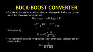
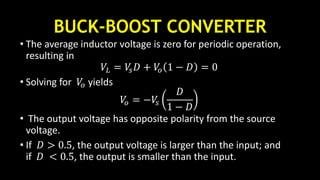
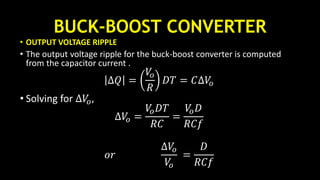
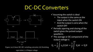
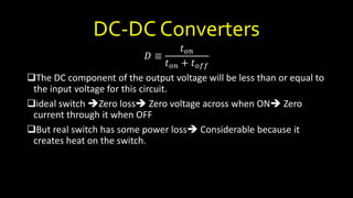
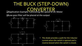
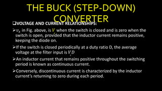
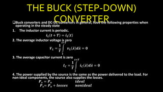
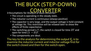
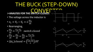
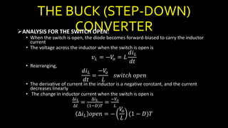
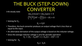
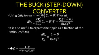
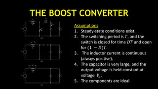
DC-DC converters are circuits that convert a DC voltage to another DC voltage level. They use switching elements like transistors and power switches to efficiently step up or step down voltage. The buck converter is a common DC-DC converter topology that can step down voltage. It uses a switch, inductor, diode, and capacitor. By periodically opening and closing the switch, the inductor filters the output to produce a lower average voltage. The output voltage of an ideal buck converter is equal to the input voltage multiplied by the duty cycle of the switch. Real converters have non-ideal components that cause additional voltage ripple. Proper component selection and design considerations are needed to minimize ripple.

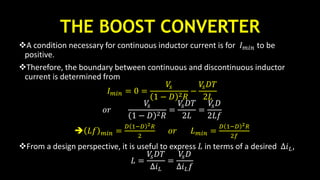
![THE BOOST CONVERTER
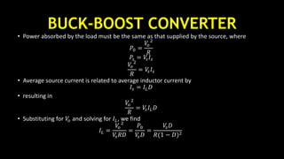
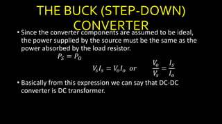
Average inductor current can be obtained by assuming 𝑃𝑠 = 𝑃𝑜
Output power is
𝑃𝑜 =
𝑉𝑜
2
𝑅
= 𝑉𝑜 𝐼 𝑜
𝑉𝑆 𝐼𝑆= 𝑉𝑠 𝐼𝐿
Equating input and output powers
𝑉𝑠 𝐼𝐿 =
𝑉𝑜
2
𝑅
=
[𝑉𝑠/(1 − 𝐷)]2
𝑅
=
𝑉𝑠
2
(1 − 𝐷)2 𝑅
𝐼𝐿 =
𝑉𝑠
(1−𝐷)2 𝑅
=
𝑉𝑜
2
𝑉𝑠 𝑅
=
𝑉𝑜 𝐼 𝑜
𝑉𝑠
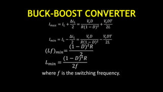
• 𝐼 𝑚𝑎𝑥 = 𝐼𝐿 +
∆𝑖 𝐿
2
=
𝑉𝑠
(1−𝐷)2 𝑅
+
𝑉𝑠 𝐷𝑇
2𝐿
• 𝐼 𝑚𝑖𝑛 = 𝐼𝐿 −
∆𝑖 𝐿
2
=
𝑉𝑠
1−𝐷 2 𝑅
−
𝑉𝑠 𝐷𝑇
2𝐿](https://image.slidesharecdn.com/dcdc-160422103913/85/DC-DC-Converter-27-320.jpg)
![THE BOOST CONVERTER
Figure: Boost converter for a nonideal inductor. (a) Output voltage;
(b) Boost converter efficiency.
𝜂 =
𝑃𝑜
𝑃𝑜 + 𝑃𝑙𝑜𝑠𝑠
=
𝑉𝑜
2
/𝑅
𝑉𝑜
2
/𝑅 + 𝐼𝐿
2
𝑟𝐿
=
𝑉𝑜
2
/𝑅
𝑉𝑜
2
/𝑅 + [(𝑉𝑜
2
/𝑅)2/ 1 − 𝐷 2] 𝑟𝐿
=
1
1 +
𝑟𝐿[𝑅 1 − 𝐷 2]](https://image.slidesharecdn.com/dcdc-160422103913/85/DC-DC-Converter-32-320.jpg)