SlideShare a Scribd company logo
General Up Conversion
• 70 MHz IF, 2.5. 8, & 22 MHz BWs (3dB).
• 204.8 MHz DAC Sample Rate
• Modem provides 25 KHz fine tune step
• Receiver/Exciter minimum freq step = 0.5 MHz, settling time < 100 us to 100Hz.
1
Modem
FPGA
DAC14DUC
Fs = 204.8 MHz
I
Q 2nd IF
70 MHz
Exciter
Tuning
Step=0.5 MHz
Tsettling
= < 100 Hz < 100us
22 MHz 8 MHz
2.5 MHz
22 MHz
1st IF
Digital Up Converter
• Baseband samples are converted to 70 MHz “digital IF”
• Polyphase filter approach reduces required 204.8 Msps processing to simple data transfer.
2
18.8 MHz + 51.2 MHz = 70 MHz
14
x2 Interpolation

DAC
2
1
sinc
x2 Interpolation
NCO
sincos
2
1
sinc
+
-

+
+
Complex MixerDAC
Comp
Fine Tune
18.8 MHz ± 250 KHz
25 KHz step
Poly
Phase
FIR
Poly
Phase
FIR
Commutate
I & Q
204.8 MHz
I
Q
102.4 Msps 204.8 Msps
Baseband
Waveform
Processing
51.2 Msps
-1
-1
DUC Continued
• 204.8 Msps DAC sample rate required to reduce DAC sinx/x roll-off.
• Final 2x interpolation process employs parallel FIR (polyphase) filters that process at 1x rate.
• Number of filter taps is reduced by factor of two resulting from quarter wave frequency shift.
3
Equivalent
2
x2 Interpolation
2
 14
sin( )

n
cos( )

n
Fs = 204.8 Msps
40 Taps
40 Taps
14
x2 Interpolation
Poly
Phase
FIR
Poly
Phase
FIR
-1
Commutate
I & Q
Fs = 102.4 Msps Fs = 204.8 Msps
-1
20 Taps
20 Taps
DUC Filters
4
14
x2 Interpolation

DAC
2
x2 Interpolation
NCO
sincos
2
+
-

+
+
Complex Mixer Commutate
I & Q
204.8 MHz
I
Q
DUC Filter 1
Programmable FIR
47 Taps each
DUC Filter 2
20 Taps each
-1
-1
DUC Filter 1• 47 tap programmable FIR, 16 bit symmetric coefficients
• BW is adjusted according to waveform mode, I.e., 20, 6, or 1 MHz modes.
• Three sets of coefficients must be stored. The proper set of coefficients are
downloaded upon change in waveform BW.
5
DUC Filter 2
Simplification
• Original filter is split into even and odd phases and processed in parallel at
102.4Msps (half rate).
• Each output is selected once per 1x sample period to provide x2 rate change.
6
2
2
Even coef
Odd coef
102.4 Msps 204.8 Msps
X2 Interploation X2 Interploation
Even coef
Odd coef
Conversion
I
Q
40 taps
40 taps
40 taps
40 taps
DUC Filter 2
Simplification
• One of two filter phases can be eliminated as a result of quarter wave frequency
shift.
• Number of taps is reduced by factor of two.
• Real frequency mixer and quarter wave shift is reduced to simple commutation
between I & q filter outputs.
• Provides complex to reak conversion and fs/4 frequency shift.
7
Even coef
Odd coef
Even coef
Odd coef

-sin( )

n
cos( )

n
I
Q
={1,0,-1,0}
={0,-1,0,1}
Even coef
-120 taps
20 taps
-1Odd coef
yi
(n)
-yi
(n)
-yq
(n)
yq(n)
DUC Out
Conversion
20 taps, each
Output Sequence =
{ yi(n), -yq(n), -yi(n), yq(n), …}
DUC Filter 2
• 20 tap FIR, 16 bit symmetric coefficients.
8
40 taps
h0
,h2
,h4
,...h38
Even
Coef
Odd
Coef
h
1 ,h
3 ,h
5 ,...h
39
I Channel
Q Channel
20 taps
20 taps
DUC Output After 1st
Interpolation
9
14
x2 Interpolation

DAC
2
x2 Interpolation
2
+
-

+
+
Complex Mixer Commutate
I & Q
204.8 MHz
I
Q
-1
-1
-120
-100
-80
-60
-40
-20
0
20
0 12.8 25.6 38.4 51.2 64 76.8 89.6 102.4
MHz
dB
DUC Filter1
Signal
-120
-100
-80
-60
-40
-20
0
20
0 12.8 25.6 38.4 51.2 64 76.8 89.6 102.4
f/fs
dB
Shifted Signal
DUC Output Spectrum
10
DUC Output
20 MHz & 1 MHz Waveform Modes
-120
-100
-80
-60
-40
-20
0
20
0 25.6 51.2 76.8 102.4 128 153.6 179.2 204.8
MHz
dB
20 MHz
1 MHz
NOTE: Analog IF
Filters provide >80
dB additional
rejection @ 30 MHz
bandwidth.
General Down Conversion
• 70 MHz IF, 2.5. 8, & 22 MHz BWs (3dB).
• 102.4 MHz ADC Sample Rate
• Modem provides 25 KHz fine tune step
• Receiver/Exciter minimum freq step = 0.5 MHz, settling time < 100 us to 100Hz.
11
Modem
FPGA
14DDC
Fs = 102.4 MHz
I
Q 2nd IF
70 MHz
Receiver
22 MHz 8 MHz
2.5 MHz
22 MHz
1st IF
ADC
Tuning
Step=0.5 MHz
Tsettling
= < 100 Hz < 100us
Digital Down Converter
12
102.4 Msps51.2 Msps
12
ADC
102.4 MHz
sincos
NCO
47 tap FIR
47 tap FIR
2
2
I/Q
FFT / PSAM
Freq Error
Tune Freq
Freq Constant
Digital Down Converter
Sync
Timing/Freq
Timing/FreqError
Baseband
Waveform Processing
DDC Output Spectrum
13
DDC / DUC Commonality
• The DDC filter (47 tap) and DUC filter #1 are the same. The
DDC and DUC can share the same FPGA filter structures.
• The DDC and DUC share a single DDS FPGA instantiation.
14
DDC / DUC Commonality
15
14

DAC
2
2
+
-

+
+
204.8 MHz
I
Q
-1
-1
12
ADC
102.4 MHz
-sin
cos
NCO
47 tap FIR
47 tap FIRI/Q
Freq Constant
Digital Down Converter
Freq Error
Tune Freq 
2
2
Sync
Timing/Freq
Digital Up Converter
I
Q
47 tap FIR
47 tap FIR
20 tap FIR
20 tap FIR
Common
Filter.
I/Q filter
pair is
instantiated
once in
FPGA and
shared
between
DDC and
DUC.
Common
NCO/DDS
Shared
between DUC
and DDC.
Direct Digital Synthesizer (DDS)
• DDS is implemented using Xilinx ip with Taylor series phase
correction.
• SFDR  -115 dB
• Df < 1 Hz
• Phase Accumulator = 32 bits
• cos & -sin outputs = 20 bits
16
Direct Digital Synthesizer (DDS)
• Output frequency is a combination of a constant frequency
term, tune frequency term, and error frequency term.
17
MHzf
KHzfKHz
KHzfKHz
where
f
f
fMHzf
ffMHzf
clk
error
tune
clk
out
tuneout
errortuneout
4.102
1111
sizestep25KHz,250250
:
2
8.18:CaseDUC
4.32:CaseDDC
32




D



Frequency Uncertainty/Error
• Specifications
• Reference Frequency = +/- 1 ppm
• Max Doppler Velocity = 700 m/s
18
Hz
HzMHz
sme
sm
f
c
v
HzMHzppm
833,10yUncertaintFrequencyTotal
58332500
/83
/700
ErrorDopplerMax
500022500*1ErrorReference



Frequency Correction
Rx Packet
• Frequency Error is determined during Synchronization
process and applied prior to demodulating Rx packet. (See
timing charts.)
Tx Packet
• Frequency error term = 0 for Tx slots.
19
DDC/DUC Processing
• Maintain 16 bits in/out of DDC and DUC.
• Complex mixer functions should maintain 18 bits at input and truncate
to 16 bits at output.
20
DDS
(NCO)
20 bits 18 bitscos
-sin 20 bits
Truncate
18 bits16 bits
Filter/
Decimate
16 bits
Baseband
Processing
DDC
I or Q
From ADC

More Related Content

What's hot

Matched filter detection
Matched filter detectionMatched filter detection
Matched filter detection
SURYA DEEPAK
 
Design and implementation of qpsk modulator using digital subcarrier
Design and implementation of qpsk modulator using digital subcarrierDesign and implementation of qpsk modulator using digital subcarrier
Design and implementation of qpsk modulator using digital subcarrier
Gongadi Nagaraju
 
ASK FSK PSK Introduction
ASK FSK PSK IntroductionASK FSK PSK Introduction
ASK FSK PSK Introduction
deivanayagamramachan
 
Ofdm tutorial fuyun_ling_rev1
Ofdm tutorial fuyun_ling_rev1Ofdm tutorial fuyun_ling_rev1
Ofdm tutorial fuyun_ling_rev1Fuyun Ling
 
Rf receiver design case studies
Rf receiver design case studiesRf receiver design case studies
Rf receiver design case studiesPhani Kumar
 
Multirate DSP
Multirate DSPMultirate DSP
Multirate DSP
@zenafaris91
 
Basics of analog communication system
Basics of analog communication systemBasics of analog communication system
Basics of analog communication system
swatihalunde
 
Ee424 fading
Ee424 fadingEe424 fading
Ee424 fading
Shraddha Bansal
 
259711021-LTE-Training.pptx
259711021-LTE-Training.pptx259711021-LTE-Training.pptx
259711021-LTE-Training.pptx
ssuser6f5356
 
Broadside array vs end fire array
Broadside array vs end fire arrayBroadside array vs end fire array
Broadside array vs end fire array
AJAL A J
 
Hardware Implementation Of QPSK Modulator for Satellite Communications
Hardware Implementation Of QPSK Modulator for Satellite CommunicationsHardware Implementation Of QPSK Modulator for Satellite Communications
Hardware Implementation Of QPSK Modulator for Satellite Communications
pradeepps88
 
Small scale fading
Small scale fadingSmall scale fading
Small scale fading
AJAL A J
 
AIRCOM LTE Webinar 2 - Air Interface
AIRCOM LTE Webinar 2 - Air InterfaceAIRCOM LTE Webinar 2 - Air Interface
AIRCOM LTE Webinar 2 - Air Interface
AIRCOM International
 
Digital Modulation
Digital Modulation Digital Modulation
Digital Modulation
Ridwanul Hoque
 
Power delay profile,delay spread and doppler spread
Power delay profile,delay spread and doppler spreadPower delay profile,delay spread and doppler spread
Power delay profile,delay spread and doppler spreadManish Srivastava
 
Adaptive Beamforming Algorithms
Adaptive Beamforming Algorithms Adaptive Beamforming Algorithms
Adaptive Beamforming Algorithms
Mohammed Abuibaid
 
Antenna arrays
Antenna arraysAntenna arrays
Antenna arrays
AJAL A J
 
Small scale fading and multipath measurements
Small scale fading and multipath measurementsSmall scale fading and multipath measurements
Small scale fading and multipath measurements
Vrince Vimal
 
F01 beam forming_srs
F01 beam forming_srsF01 beam forming_srs
F01 beam forming_srs
Luciano Motta
 

What's hot (20)

Matched filter detection
Matched filter detectionMatched filter detection
Matched filter detection
 
Design and implementation of qpsk modulator using digital subcarrier
Design and implementation of qpsk modulator using digital subcarrierDesign and implementation of qpsk modulator using digital subcarrier
Design and implementation of qpsk modulator using digital subcarrier
 
ASK FSK PSK Introduction
ASK FSK PSK IntroductionASK FSK PSK Introduction
ASK FSK PSK Introduction
 
Ofdm tutorial fuyun_ling_rev1
Ofdm tutorial fuyun_ling_rev1Ofdm tutorial fuyun_ling_rev1
Ofdm tutorial fuyun_ling_rev1
 
Rf receiver design case studies
Rf receiver design case studiesRf receiver design case studies
Rf receiver design case studies
 
Multirate DSP
Multirate DSPMultirate DSP
Multirate DSP
 
Basics of analog communication system
Basics of analog communication systemBasics of analog communication system
Basics of analog communication system
 
Ee424 fading
Ee424 fadingEe424 fading
Ee424 fading
 
259711021-LTE-Training.pptx
259711021-LTE-Training.pptx259711021-LTE-Training.pptx
259711021-LTE-Training.pptx
 
Broadside array vs end fire array
Broadside array vs end fire arrayBroadside array vs end fire array
Broadside array vs end fire array
 
Hardware Implementation Of QPSK Modulator for Satellite Communications
Hardware Implementation Of QPSK Modulator for Satellite CommunicationsHardware Implementation Of QPSK Modulator for Satellite Communications
Hardware Implementation Of QPSK Modulator for Satellite Communications
 
Small scale fading
Small scale fadingSmall scale fading
Small scale fading
 
AIRCOM LTE Webinar 2 - Air Interface
AIRCOM LTE Webinar 2 - Air InterfaceAIRCOM LTE Webinar 2 - Air Interface
AIRCOM LTE Webinar 2 - Air Interface
 
Digital Modulation
Digital Modulation Digital Modulation
Digital Modulation
 
Power delay profile,delay spread and doppler spread
Power delay profile,delay spread and doppler spreadPower delay profile,delay spread and doppler spread
Power delay profile,delay spread and doppler spread
 
Microwave link design
Microwave link designMicrowave link design
Microwave link design
 
Adaptive Beamforming Algorithms
Adaptive Beamforming Algorithms Adaptive Beamforming Algorithms
Adaptive Beamforming Algorithms
 
Antenna arrays
Antenna arraysAntenna arrays
Antenna arrays
 
Small scale fading and multipath measurements
Small scale fading and multipath measurementsSmall scale fading and multipath measurements
Small scale fading and multipath measurements
 
F01 beam forming_srs
F01 beam forming_srsF01 beam forming_srs
F01 beam forming_srs
 

Viewers also liked

E paper ssk times sep - 15
E paper ssk times sep - 15E paper ssk times sep - 15
E paper ssk times sep - 15
ssktimes
 
IMS2015_DelfMEMS_final
IMS2015_DelfMEMS_finalIMS2015_DelfMEMS_final
IMS2015_DelfMEMS_finalIgor Lalicevic
 
Data Conversion: Hard Problems Made Easy - VE2013
Data Conversion: Hard Problems Made Easy - VE2013Data Conversion: Hard Problems Made Easy - VE2013
Data Conversion: Hard Problems Made Easy - VE2013
Analog Devices, Inc.
 
Integrated Software-Defined Radio (SDR) - VE2013
Integrated Software-Defined Radio (SDR) - VE2013Integrated Software-Defined Radio (SDR) - VE2013
Integrated Software-Defined Radio (SDR) - VE2013
Analog Devices, Inc.
 
What is 16 qam modulation
What is 16 qam modulationWhat is 16 qam modulation
What is 16 qam modulation
FOSCO Fiber Optics
 
Digital modulation techniques...
Digital modulation techniques...Digital modulation techniques...
Digital modulation techniques...
Nidhi Baranwal
 
Digital modulation
Digital modulationDigital modulation
Digital modulationIbrahim Omar
 
Digital Modulation Techniques ppt
Digital Modulation Techniques pptDigital Modulation Techniques ppt
Digital Modulation Techniques ppt
Pankaj Singh
 
Digital modulation
Digital modulationDigital modulation
Digital modulation
Ankur Kumar
 
Digital modulation techniques
Digital modulation techniquesDigital modulation techniques
Digital modulation techniquessrkrishna341
 
RF Front End modules and components for cellphones 2017 - Report by Yole Deve...
RF Front End modules and components for cellphones 2017 - Report by Yole Deve...RF Front End modules and components for cellphones 2017 - Report by Yole Deve...
RF Front End modules and components for cellphones 2017 - Report by Yole Deve...
Yole Developpement
 
Deep Learning - The Past, Present and Future of Artificial Intelligence
Deep Learning - The Past, Present and Future of Artificial IntelligenceDeep Learning - The Past, Present and Future of Artificial Intelligence
Deep Learning - The Past, Present and Future of Artificial Intelligence
Lukas Masuch
 

Viewers also liked (14)

E paper ssk times sep - 15
E paper ssk times sep - 15E paper ssk times sep - 15
E paper ssk times sep - 15
 
IMS2015_DelfMEMS_final
IMS2015_DelfMEMS_finalIMS2015_DelfMEMS_final
IMS2015_DelfMEMS_final
 
Data Conversion: Hard Problems Made Easy - VE2013
Data Conversion: Hard Problems Made Easy - VE2013Data Conversion: Hard Problems Made Easy - VE2013
Data Conversion: Hard Problems Made Easy - VE2013
 
Neeraj kumar
Neeraj kumarNeeraj kumar
Neeraj kumar
 
Integrated Software-Defined Radio (SDR) - VE2013
Integrated Software-Defined Radio (SDR) - VE2013Integrated Software-Defined Radio (SDR) - VE2013
Integrated Software-Defined Radio (SDR) - VE2013
 
What is 16 qam modulation
What is 16 qam modulationWhat is 16 qam modulation
What is 16 qam modulation
 
Adc dac converter
Adc dac converterAdc dac converter
Adc dac converter
 
Digital modulation techniques...
Digital modulation techniques...Digital modulation techniques...
Digital modulation techniques...
 
Digital modulation
Digital modulationDigital modulation
Digital modulation
 
Digital Modulation Techniques ppt
Digital Modulation Techniques pptDigital Modulation Techniques ppt
Digital Modulation Techniques ppt
 
Digital modulation
Digital modulationDigital modulation
Digital modulation
 
Digital modulation techniques
Digital modulation techniquesDigital modulation techniques
Digital modulation techniques
 
RF Front End modules and components for cellphones 2017 - Report by Yole Deve...
RF Front End modules and components for cellphones 2017 - Report by Yole Deve...RF Front End modules and components for cellphones 2017 - Report by Yole Deve...
RF Front End modules and components for cellphones 2017 - Report by Yole Deve...
 
Deep Learning - The Past, Present and Future of Artificial Intelligence
Deep Learning - The Past, Present and Future of Artificial IntelligenceDeep Learning - The Past, Present and Future of Artificial Intelligence
Deep Learning - The Past, Present and Future of Artificial Intelligence
 

Similar to General/Digital up conversion

Real 2nd order LC PLL loop analysis.pptx
Real 2nd order LC PLL loop analysis.pptxReal 2nd order LC PLL loop analysis.pptx
Real 2nd order LC PLL loop analysis.pptx
SaiGouthamSunkara
 
Krishnan_defence.ppt
Krishnan_defence.pptKrishnan_defence.ppt
Krishnan_defence.ppt
berk51
 
IEEE_RFIC 2007
IEEE_RFIC 2007 IEEE_RFIC 2007
IEEE_RFIC 2007
wence00
 
DSP_2018_FOEHU - Lec 07 - IIR Filter Design
DSP_2018_FOEHU - Lec 07 - IIR Filter DesignDSP_2018_FOEHU - Lec 07 - IIR Filter Design
DSP_2018_FOEHU - Lec 07 - IIR Filter Design
Amr E. Mohamed
 
synathesized function generator
synathesized function generatorsynathesized function generator
synathesized function generatorJay Patel
 
Synchronous Time / Frequency Domain Measurements Using a Digital Oscilloscope...
Synchronous Time / Frequency Domain Measurements Using a Digital Oscilloscope...Synchronous Time / Frequency Domain Measurements Using a Digital Oscilloscope...
Synchronous Time / Frequency Domain Measurements Using a Digital Oscilloscope...
Rohde & Schwarz North America
 
Active filters
Active filtersActive filters
Active filters
Vinayak Bairagi
 
AD8351.pdf
AD8351.pdfAD8351.pdf
PLL_tutorial_slides.pdf
PLL_tutorial_slides.pdfPLL_tutorial_slides.pdf
PLL_tutorial_slides.pdf
ssuser716da4
 
Design of Energy- and Area-Efficient Sensor Readout Circuits (Chih-Chan Tu)
Design of Energy- and Area-Efficient Sensor Readout Circuits (Chih-Chan Tu)Design of Energy- and Area-Efficient Sensor Readout Circuits (Chih-Chan Tu)
Design of Energy- and Area-Efficient Sensor Readout Circuits (Chih-Chan Tu)
Chih-Chan Tu
 
Ims2016 micro apps_robertbrennan_pll_frequencyplanning_v2
Ims2016 micro apps_robertbrennan_pll_frequencyplanning_v2Ims2016 micro apps_robertbrennan_pll_frequencyplanning_v2
Ims2016 micro apps_robertbrennan_pll_frequencyplanning_v2
Analog Devices, Inc.
 
ADC and its Circuit design
ADC and its Circuit designADC and its Circuit design
ADC and its Circuit design
Vihari Andukuri
 
Fundamentals of Analog and Digital Modulation PPT.pptx
Fundamentals of Analog and Digital  Modulation PPT.pptxFundamentals of Analog and Digital  Modulation PPT.pptx
Fundamentals of Analog and Digital Modulation PPT.pptx
SarmistaSengupta1
 
Frequency-Shift Keying
Frequency-Shift KeyingFrequency-Shift Keying
Frequency-Shift Keying
Jessie Rama
 
Fir filter_utkarsh_kulshrestha
Fir filter_utkarsh_kulshresthaFir filter_utkarsh_kulshrestha
Fir filter_utkarsh_kulshrestha
Utkarsh Kulshrestha
 
RT15 Berkeley | Requirements on Power Amplifiers and HIL Real-Time Processors...
RT15 Berkeley | Requirements on Power Amplifiers and HIL Real-Time Processors...RT15 Berkeley | Requirements on Power Amplifiers and HIL Real-Time Processors...
RT15 Berkeley | Requirements on Power Amplifiers and HIL Real-Time Processors...
OPAL-RT TECHNOLOGIES
 
9420 datasheet
9420 datasheet9420 datasheet
9420 datasheet
Quantum Composers
 
RM03D-3_DCOBISC_06_07_09_Final
RM03D-3_DCOBISC_06_07_09_FinalRM03D-3_DCOBISC_06_07_09_Final
RM03D-3_DCOBISC_06_07_09_Finalimranbashir
 

Similar to General/Digital up conversion (20)

Real 2nd order LC PLL loop analysis.pptx
Real 2nd order LC PLL loop analysis.pptxReal 2nd order LC PLL loop analysis.pptx
Real 2nd order LC PLL loop analysis.pptx
 
Krishnan_defence.ppt
Krishnan_defence.pptKrishnan_defence.ppt
Krishnan_defence.ppt
 
IEEE_RFIC 2007
IEEE_RFIC 2007 IEEE_RFIC 2007
IEEE_RFIC 2007
 
DSP_2018_FOEHU - Lec 07 - IIR Filter Design
DSP_2018_FOEHU - Lec 07 - IIR Filter DesignDSP_2018_FOEHU - Lec 07 - IIR Filter Design
DSP_2018_FOEHU - Lec 07 - IIR Filter Design
 
synathesized function generator
synathesized function generatorsynathesized function generator
synathesized function generator
 
Synchronous Time / Frequency Domain Measurements Using a Digital Oscilloscope...
Synchronous Time / Frequency Domain Measurements Using a Digital Oscilloscope...Synchronous Time / Frequency Domain Measurements Using a Digital Oscilloscope...
Synchronous Time / Frequency Domain Measurements Using a Digital Oscilloscope...
 
Active filters
Active filtersActive filters
Active filters
 
FFaraji
FFarajiFFaraji
FFaraji
 
AD8351.pdf
AD8351.pdfAD8351.pdf
AD8351.pdf
 
PLL_tutorial_slides.pdf
PLL_tutorial_slides.pdfPLL_tutorial_slides.pdf
PLL_tutorial_slides.pdf
 
Design of Energy- and Area-Efficient Sensor Readout Circuits (Chih-Chan Tu)
Design of Energy- and Area-Efficient Sensor Readout Circuits (Chih-Chan Tu)Design of Energy- and Area-Efficient Sensor Readout Circuits (Chih-Chan Tu)
Design of Energy- and Area-Efficient Sensor Readout Circuits (Chih-Chan Tu)
 
Ims2016 micro apps_robertbrennan_pll_frequencyplanning_v2
Ims2016 micro apps_robertbrennan_pll_frequencyplanning_v2Ims2016 micro apps_robertbrennan_pll_frequencyplanning_v2
Ims2016 micro apps_robertbrennan_pll_frequencyplanning_v2
 
ADC and its Circuit design
ADC and its Circuit designADC and its Circuit design
ADC and its Circuit design
 
Fundamentals of Analog and Digital Modulation PPT.pptx
Fundamentals of Analog and Digital  Modulation PPT.pptxFundamentals of Analog and Digital  Modulation PPT.pptx
Fundamentals of Analog and Digital Modulation PPT.pptx
 
Ad7716
Ad7716Ad7716
Ad7716
 
Frequency-Shift Keying
Frequency-Shift KeyingFrequency-Shift Keying
Frequency-Shift Keying
 
Fir filter_utkarsh_kulshrestha
Fir filter_utkarsh_kulshresthaFir filter_utkarsh_kulshrestha
Fir filter_utkarsh_kulshrestha
 
RT15 Berkeley | Requirements on Power Amplifiers and HIL Real-Time Processors...
RT15 Berkeley | Requirements on Power Amplifiers and HIL Real-Time Processors...RT15 Berkeley | Requirements on Power Amplifiers and HIL Real-Time Processors...
RT15 Berkeley | Requirements on Power Amplifiers and HIL Real-Time Processors...
 
9420 datasheet
9420 datasheet9420 datasheet
9420 datasheet
 
RM03D-3_DCOBISC_06_07_09_Final
RM03D-3_DCOBISC_06_07_09_FinalRM03D-3_DCOBISC_06_07_09_Final
RM03D-3_DCOBISC_06_07_09_Final
 

Recently uploaded

AKS UNIVERSITY Satna Final Year Project By OM Hardaha.pdf
AKS UNIVERSITY Satna Final Year Project By OM Hardaha.pdfAKS UNIVERSITY Satna Final Year Project By OM Hardaha.pdf
AKS UNIVERSITY Satna Final Year Project By OM Hardaha.pdf
SamSarthak3
 
Design and Analysis of Algorithms-DP,Backtracking,Graphs,B&B
Design and Analysis of Algorithms-DP,Backtracking,Graphs,B&BDesign and Analysis of Algorithms-DP,Backtracking,Graphs,B&B
Design and Analysis of Algorithms-DP,Backtracking,Graphs,B&B
Sreedhar Chowdam
 
Nuclear Power Economics and Structuring 2024
Nuclear Power Economics and Structuring 2024Nuclear Power Economics and Structuring 2024
Nuclear Power Economics and Structuring 2024
Massimo Talia
 
Water Industry Process Automation and Control Monthly - May 2024.pdf
Water Industry Process Automation and Control Monthly - May 2024.pdfWater Industry Process Automation and Control Monthly - May 2024.pdf
Water Industry Process Automation and Control Monthly - May 2024.pdf
Water Industry Process Automation & Control
 
ASME IX(9) 2007 Full Version .pdf
ASME IX(9)  2007 Full Version       .pdfASME IX(9)  2007 Full Version       .pdf
ASME IX(9) 2007 Full Version .pdf
AhmedHussein950959
 
Student information management system project report ii.pdf
Student information management system project report ii.pdfStudent information management system project report ii.pdf
Student information management system project report ii.pdf
Kamal Acharya
 
Automobile Management System Project Report.pdf
Automobile Management System Project Report.pdfAutomobile Management System Project Report.pdf
Automobile Management System Project Report.pdf
Kamal Acharya
 
MCQ Soil mechanics questions (Soil shear strength).pdf
MCQ Soil mechanics questions (Soil shear strength).pdfMCQ Soil mechanics questions (Soil shear strength).pdf
MCQ Soil mechanics questions (Soil shear strength).pdf
Osamah Alsalih
 
H.Seo, ICLR 2024, MLILAB, KAIST AI.pdf
H.Seo,  ICLR 2024, MLILAB,  KAIST AI.pdfH.Seo,  ICLR 2024, MLILAB,  KAIST AI.pdf
H.Seo, ICLR 2024, MLILAB, KAIST AI.pdf
MLILAB
 
block diagram and signal flow graph representation
block diagram and signal flow graph representationblock diagram and signal flow graph representation
block diagram and signal flow graph representation
Divya Somashekar
 
addressing modes in computer architecture
addressing modes  in computer architectureaddressing modes  in computer architecture
addressing modes in computer architecture
ShahidSultan24
 
Railway Signalling Principles Edition 3.pdf
Railway Signalling Principles Edition 3.pdfRailway Signalling Principles Edition 3.pdf
Railway Signalling Principles Edition 3.pdf
TeeVichai
 
COLLEGE BUS MANAGEMENT SYSTEM PROJECT REPORT.pdf
COLLEGE BUS MANAGEMENT SYSTEM PROJECT REPORT.pdfCOLLEGE BUS MANAGEMENT SYSTEM PROJECT REPORT.pdf
COLLEGE BUS MANAGEMENT SYSTEM PROJECT REPORT.pdf
Kamal Acharya
 
Quality defects in TMT Bars, Possible causes and Potential Solutions.
Quality defects in TMT Bars, Possible causes and Potential Solutions.Quality defects in TMT Bars, Possible causes and Potential Solutions.
Quality defects in TMT Bars, Possible causes and Potential Solutions.
PrashantGoswami42
 
HYDROPOWER - Hydroelectric power generation
HYDROPOWER - Hydroelectric power generationHYDROPOWER - Hydroelectric power generation
HYDROPOWER - Hydroelectric power generation
Robbie Edward Sayers
 
Planning Of Procurement o different goods and services
Planning Of Procurement o different goods and servicesPlanning Of Procurement o different goods and services
Planning Of Procurement o different goods and services
JoytuBarua2
 
Vaccine management system project report documentation..pdf
Vaccine management system project report documentation..pdfVaccine management system project report documentation..pdf
Vaccine management system project report documentation..pdf
Kamal Acharya
 
Architectural Portfolio Sean Lockwood
Architectural Portfolio Sean LockwoodArchitectural Portfolio Sean Lockwood
Architectural Portfolio Sean Lockwood
seandesed
 
在线办理(ANU毕业证书)澳洲国立大学毕业证录取通知书一模一样
在线办理(ANU毕业证书)澳洲国立大学毕业证录取通知书一模一样在线办理(ANU毕业证书)澳洲国立大学毕业证录取通知书一模一样
在线办理(ANU毕业证书)澳洲国立大学毕业证录取通知书一模一样
obonagu
 
TECHNICAL TRAINING MANUAL GENERAL FAMILIARIZATION COURSE
TECHNICAL TRAINING MANUAL   GENERAL FAMILIARIZATION COURSETECHNICAL TRAINING MANUAL   GENERAL FAMILIARIZATION COURSE
TECHNICAL TRAINING MANUAL GENERAL FAMILIARIZATION COURSE
DuvanRamosGarzon1
 

Recently uploaded (20)

AKS UNIVERSITY Satna Final Year Project By OM Hardaha.pdf
AKS UNIVERSITY Satna Final Year Project By OM Hardaha.pdfAKS UNIVERSITY Satna Final Year Project By OM Hardaha.pdf
AKS UNIVERSITY Satna Final Year Project By OM Hardaha.pdf
 
Design and Analysis of Algorithms-DP,Backtracking,Graphs,B&B
Design and Analysis of Algorithms-DP,Backtracking,Graphs,B&BDesign and Analysis of Algorithms-DP,Backtracking,Graphs,B&B
Design and Analysis of Algorithms-DP,Backtracking,Graphs,B&B
 
Nuclear Power Economics and Structuring 2024
Nuclear Power Economics and Structuring 2024Nuclear Power Economics and Structuring 2024
Nuclear Power Economics and Structuring 2024
 
Water Industry Process Automation and Control Monthly - May 2024.pdf
Water Industry Process Automation and Control Monthly - May 2024.pdfWater Industry Process Automation and Control Monthly - May 2024.pdf
Water Industry Process Automation and Control Monthly - May 2024.pdf
 
ASME IX(9) 2007 Full Version .pdf
ASME IX(9)  2007 Full Version       .pdfASME IX(9)  2007 Full Version       .pdf
ASME IX(9) 2007 Full Version .pdf
 
Student information management system project report ii.pdf
Student information management system project report ii.pdfStudent information management system project report ii.pdf
Student information management system project report ii.pdf
 
Automobile Management System Project Report.pdf
Automobile Management System Project Report.pdfAutomobile Management System Project Report.pdf
Automobile Management System Project Report.pdf
 
MCQ Soil mechanics questions (Soil shear strength).pdf
MCQ Soil mechanics questions (Soil shear strength).pdfMCQ Soil mechanics questions (Soil shear strength).pdf
MCQ Soil mechanics questions (Soil shear strength).pdf
 
H.Seo, ICLR 2024, MLILAB, KAIST AI.pdf
H.Seo,  ICLR 2024, MLILAB,  KAIST AI.pdfH.Seo,  ICLR 2024, MLILAB,  KAIST AI.pdf
H.Seo, ICLR 2024, MLILAB, KAIST AI.pdf
 
block diagram and signal flow graph representation
block diagram and signal flow graph representationblock diagram and signal flow graph representation
block diagram and signal flow graph representation
 
addressing modes in computer architecture
addressing modes  in computer architectureaddressing modes  in computer architecture
addressing modes in computer architecture
 
Railway Signalling Principles Edition 3.pdf
Railway Signalling Principles Edition 3.pdfRailway Signalling Principles Edition 3.pdf
Railway Signalling Principles Edition 3.pdf
 
COLLEGE BUS MANAGEMENT SYSTEM PROJECT REPORT.pdf
COLLEGE BUS MANAGEMENT SYSTEM PROJECT REPORT.pdfCOLLEGE BUS MANAGEMENT SYSTEM PROJECT REPORT.pdf
COLLEGE BUS MANAGEMENT SYSTEM PROJECT REPORT.pdf
 
Quality defects in TMT Bars, Possible causes and Potential Solutions.
Quality defects in TMT Bars, Possible causes and Potential Solutions.Quality defects in TMT Bars, Possible causes and Potential Solutions.
Quality defects in TMT Bars, Possible causes and Potential Solutions.
 
HYDROPOWER - Hydroelectric power generation
HYDROPOWER - Hydroelectric power generationHYDROPOWER - Hydroelectric power generation
HYDROPOWER - Hydroelectric power generation
 
Planning Of Procurement o different goods and services
Planning Of Procurement o different goods and servicesPlanning Of Procurement o different goods and services
Planning Of Procurement o different goods and services
 
Vaccine management system project report documentation..pdf
Vaccine management system project report documentation..pdfVaccine management system project report documentation..pdf
Vaccine management system project report documentation..pdf
 
Architectural Portfolio Sean Lockwood
Architectural Portfolio Sean LockwoodArchitectural Portfolio Sean Lockwood
Architectural Portfolio Sean Lockwood
 
在线办理(ANU毕业证书)澳洲国立大学毕业证录取通知书一模一样
在线办理(ANU毕业证书)澳洲国立大学毕业证录取通知书一模一样在线办理(ANU毕业证书)澳洲国立大学毕业证录取通知书一模一样
在线办理(ANU毕业证书)澳洲国立大学毕业证录取通知书一模一样
 
TECHNICAL TRAINING MANUAL GENERAL FAMILIARIZATION COURSE
TECHNICAL TRAINING MANUAL   GENERAL FAMILIARIZATION COURSETECHNICAL TRAINING MANUAL   GENERAL FAMILIARIZATION COURSE
TECHNICAL TRAINING MANUAL GENERAL FAMILIARIZATION COURSE
 

General/Digital up conversion

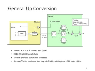
  • 1. General Up Conversion • 70 MHz IF, 2.5. 8, & 22 MHz BWs (3dB). • 204.8 MHz DAC Sample Rate • Modem provides 25 KHz fine tune step • Receiver/Exciter minimum freq step = 0.5 MHz, settling time < 100 us to 100Hz. 1 Modem FPGA DAC14DUC Fs = 204.8 MHz I Q 2nd IF 70 MHz Exciter Tuning Step=0.5 MHz Tsettling = < 100 Hz < 100us 22 MHz 8 MHz 2.5 MHz 22 MHz 1st IF
  • 2. Digital Up Converter • Baseband samples are converted to 70 MHz “digital IF” • Polyphase filter approach reduces required 204.8 Msps processing to simple data transfer. 2 18.8 MHz + 51.2 MHz = 70 MHz 14 x2 Interpolation  DAC 2 1 sinc x2 Interpolation NCO sincos 2 1 sinc + -  + + Complex MixerDAC Comp Fine Tune 18.8 MHz ± 250 KHz 25 KHz step Poly Phase FIR Poly Phase FIR Commutate I & Q 204.8 MHz I Q 102.4 Msps 204.8 Msps Baseband Waveform Processing 51.2 Msps -1 -1
  • 3. DUC Continued • 204.8 Msps DAC sample rate required to reduce DAC sinx/x roll-off. • Final 2x interpolation process employs parallel FIR (polyphase) filters that process at 1x rate. • Number of filter taps is reduced by factor of two resulting from quarter wave frequency shift. 3 Equivalent 2 x2 Interpolation 2  14 sin( )  n cos( )  n Fs = 204.8 Msps 40 Taps 40 Taps 14 x2 Interpolation Poly Phase FIR Poly Phase FIR -1 Commutate I & Q Fs = 102.4 Msps Fs = 204.8 Msps -1 20 Taps 20 Taps
  • 4. DUC Filters 4 14 x2 Interpolation  DAC 2 x2 Interpolation NCO sincos 2 + -  + + Complex Mixer Commutate I & Q 204.8 MHz I Q DUC Filter 1 Programmable FIR 47 Taps each DUC Filter 2 20 Taps each -1 -1
  • 5. DUC Filter 1• 47 tap programmable FIR, 16 bit symmetric coefficients • BW is adjusted according to waveform mode, I.e., 20, 6, or 1 MHz modes. • Three sets of coefficients must be stored. The proper set of coefficients are downloaded upon change in waveform BW. 5
  • 6. DUC Filter 2 Simplification • Original filter is split into even and odd phases and processed in parallel at 102.4Msps (half rate). • Each output is selected once per 1x sample period to provide x2 rate change. 6 2 2 Even coef Odd coef 102.4 Msps 204.8 Msps 102.4 Msps 204.8 Msps X2 Interploation X2 Interploation Even coef Odd coef Conversion I Q 40 taps 40 taps 40 taps 40 taps
  • 7. DUC Filter 2 Simplification • One of two filter phases can be eliminated as a result of quarter wave frequency shift. • Number of taps is reduced by factor of two. • Real frequency mixer and quarter wave shift is reduced to simple commutation between I & q filter outputs. • Provides complex to reak conversion and fs/4 frequency shift. 7 Even coef Odd coef Even coef Odd coef  -sin( )  n cos( )  n I Q ={1,0,-1,0} ={0,-1,0,1} Even coef -120 taps 20 taps -1Odd coef yi (n) -yi (n) -yq (n) yq(n) DUC Out Conversion 20 taps, each Output Sequence = { yi(n), -yq(n), -yi(n), yq(n), …}
  • 8. DUC Filter 2 • 20 tap FIR, 16 bit symmetric coefficients. 8 40 taps h0 ,h2 ,h4 ,...h38 Even Coef Odd Coef h 1 ,h 3 ,h 5 ,...h 39 I Channel Q Channel 20 taps 20 taps
  • 9. DUC Output After 1st Interpolation 9 14 x2 Interpolation  DAC 2 x2 Interpolation 2 + -  + + Complex Mixer Commutate I & Q 204.8 MHz I Q -1 -1 -120 -100 -80 -60 -40 -20 0 20 0 12.8 25.6 38.4 51.2 64 76.8 89.6 102.4 MHz dB DUC Filter1 Signal -120 -100 -80 -60 -40 -20 0 20 0 12.8 25.6 38.4 51.2 64 76.8 89.6 102.4 f/fs dB Shifted Signal
  • 10. DUC Output Spectrum 10 DUC Output 20 MHz & 1 MHz Waveform Modes -120 -100 -80 -60 -40 -20 0 20 0 25.6 51.2 76.8 102.4 128 153.6 179.2 204.8 MHz dB 20 MHz 1 MHz NOTE: Analog IF Filters provide >80 dB additional rejection @ 30 MHz bandwidth.
  • 11. General Down Conversion • 70 MHz IF, 2.5. 8, & 22 MHz BWs (3dB). • 102.4 MHz ADC Sample Rate • Modem provides 25 KHz fine tune step • Receiver/Exciter minimum freq step = 0.5 MHz, settling time < 100 us to 100Hz. 11 Modem FPGA 14DDC Fs = 102.4 MHz I Q 2nd IF 70 MHz Receiver 22 MHz 8 MHz 2.5 MHz 22 MHz 1st IF ADC Tuning Step=0.5 MHz Tsettling = < 100 Hz < 100us
  • 12. Digital Down Converter 12 102.4 Msps51.2 Msps 12 ADC 102.4 MHz sincos NCO 47 tap FIR 47 tap FIR 2 2 I/Q FFT / PSAM Freq Error Tune Freq Freq Constant Digital Down Converter Sync Timing/Freq Timing/FreqError Baseband Waveform Processing
  • 14. DDC / DUC Commonality • The DDC filter (47 tap) and DUC filter #1 are the same. The DDC and DUC can share the same FPGA filter structures. • The DDC and DUC share a single DDS FPGA instantiation. 14
  • 15. DDC / DUC Commonality 15 14  DAC 2 2 + -  + + 204.8 MHz I Q -1 -1 12 ADC 102.4 MHz -sin cos NCO 47 tap FIR 47 tap FIRI/Q Freq Constant Digital Down Converter Freq Error Tune Freq  2 2 Sync Timing/Freq Digital Up Converter I Q 47 tap FIR 47 tap FIR 20 tap FIR 20 tap FIR Common Filter. I/Q filter pair is instantiated once in FPGA and shared between DDC and DUC. Common NCO/DDS Shared between DUC and DDC.
  • 16. Direct Digital Synthesizer (DDS) • DDS is implemented using Xilinx ip with Taylor series phase correction. • SFDR  -115 dB • Df < 1 Hz • Phase Accumulator = 32 bits • cos & -sin outputs = 20 bits 16
  • 17. Direct Digital Synthesizer (DDS) • Output frequency is a combination of a constant frequency term, tune frequency term, and error frequency term. 17 MHzf KHzfKHz KHzfKHz where f f fMHzf ffMHzf clk error tune clk out tuneout errortuneout 4.102 1111 sizestep25KHz,250250 : 2 8.18:CaseDUC 4.32:CaseDDC 32     D   
  • 18. Frequency Uncertainty/Error • Specifications • Reference Frequency = +/- 1 ppm • Max Doppler Velocity = 700 m/s 18 Hz HzMHz sme sm f c v HzMHzppm 833,10yUncertaintFrequencyTotal 58332500 /83 /700 ErrorDopplerMax 500022500*1ErrorReference   
  • 19. Frequency Correction Rx Packet • Frequency Error is determined during Synchronization process and applied prior to demodulating Rx packet. (See timing charts.) Tx Packet • Frequency error term = 0 for Tx slots. 19
  • 20. DDC/DUC Processing • Maintain 16 bits in/out of DDC and DUC. • Complex mixer functions should maintain 18 bits at input and truncate to 16 bits at output. 20 DDS (NCO) 20 bits 18 bitscos -sin 20 bits Truncate 18 bits16 bits Filter/ Decimate 16 bits Baseband Processing DDC I or Q From ADC