Downloaded 132 times


![Least Mean Squares (LMS) Algorithm
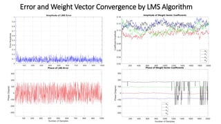
LMS Algorithm Summary
The LMS algorithm for a 𝑝 𝑡ℎorder algorithm can be
summarized as:
Parameters: 𝑝 = filter order
𝜇 = step size
Initialization: ℎ 0 = 𝑧𝑒𝑟𝑜𝑠(𝑝)
Computation: For 𝑛 = 0,1,2, . . .
𝑥 𝑛 = [𝑥 𝑛 , 𝑥 𝑛 − 1 , . . . , 𝑥 𝑛 − 𝑝 + 1 ] 𝑇
𝑒 𝑛 = 𝑑 𝑛 − ℎ 𝐻(𝑛) 𝑥 𝑛
ℎ 𝑛 + 1 = ℎ 𝑛 − 𝜇𝑒∗ 𝑛 𝑥 𝑛
Advantages & DisAdvantages of LMS algorithm:
1. Simplicity in implementation
2. Stable and robust performance against different
signal conditions
3. Slow convergence (due to eigenvalue spread)](https://image.slidesharecdn.com/presentationadaptivebfmohammedabuibaid-180123232814-180924001100/85/Adaptive-Beamforming-Algorithms-7-320.jpg)
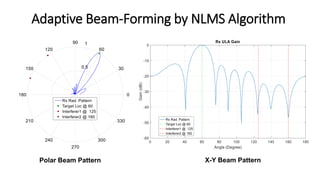
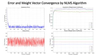
![Normalized LMS Algorithm
NLMS Algorithm Summary
The NLMS algorithm for a 𝒑 𝒕𝒉
order algorithm can be summarized as:
Parameters: 𝑝 = filter order
𝜇 = step size
Initialization: ℎ 0 = 𝑧𝑒𝑟𝑜𝑠(𝑝)
Computation: For 𝑛 = 0,1,2, . . .
𝑥 𝑛 = [𝑥 𝑛 , 𝑥 𝑛 − 1 , . . . , 𝑥 𝑛 − 𝑝 + 1 ] 𝑇
𝑒 𝑛 = 𝑑 𝑛 − ℎ 𝐻
(𝑛) 𝑥 𝑛
ℎ 𝑛 + 1 = ℎ 𝑛 −
𝜇𝑒∗
𝑛 𝑥 𝑛
𝑥 𝐻 𝑛 𝑥 𝑛
Improvements on ‘Pure’ LMS algorithm:
LMS algorithm is sensitive to the scaling of its input 𝑥 𝑛
Choosing a learning rate 𝜇 that guarantees stability of
LMS algorithm is impossible.
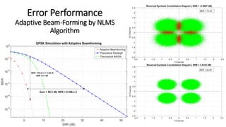
NLMS Algorithm solves this problem by normalizing with
the power of the input, thereby converging faster than
LMS](https://image.slidesharecdn.com/presentationadaptivebfmohammedabuibaid-180123232814-180924001100/85/Adaptive-Beamforming-Algorithms-11-320.jpg)
![Recursive Least Square (RLS) Algorithm
RLS Algorithm Summary
The RLS algorithm for a 𝒑 𝒕𝒉
order RLS filter can be
summarized as:
Parameters: 𝑝 = filter order
𝜆 = forgetting factor
𝛿 = value to initialize 𝑷 0
Initialization : 𝑤 𝑛 = 0
𝑥 𝑘 = 0, 𝑘 = −𝑝, . . . , −1
𝑑 𝑘 = 0, 𝑘 = −𝑝, . . . , −1
𝑷 0 = 𝛿−1
𝐼 𝑝×𝑝
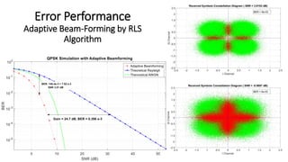
Advantages & DisAdvantages of RLS algorithm:
No need to invert matrices, thereby saving computational
power.
It provides intuition behind its results.
Faster than LMS and NLMS but more complex
Computation: For 𝑛 = 0,1,2, . . .
𝑥 𝑛 = [𝑥 𝑛 , 𝑥 𝑛 − 1 , . . . , 𝑥 𝑛 − 𝑝 ] 𝑇
𝛼 𝑛 = 𝑑 𝑛 − 𝑥 𝑇(𝑛) 𝑤 𝑛 − 1
𝒈 𝑛 =
𝑷 𝑛 − 1 𝑥∗ 𝑛
𝜆 + 𝑥 𝑇 𝑛 𝑷 𝑛 − 1 𝑥∗ 𝑛
𝑷 𝑛 = 𝜆−1 𝑷 𝑛 − 1 − 𝑔 𝑛 𝑥 𝑇(𝑛)𝜆−1 𝑷 𝑛 − 1
w 𝑛 = 𝑤 𝑛 − 1 − 𝛼(𝑛) 𝑔 𝑛](https://image.slidesharecdn.com/presentationadaptivebfmohammedabuibaid-180123232814-180924001100/85/Adaptive-Beamforming-Algorithms-15-320.jpg)

![References
[1] http://www.dailysabah.com/technology/2015/08/26/turkeys-45g-mobile-technology-tender-concludes-with-a-record-bid-
of-396-billion
[2] http://www.huawei.com/en/news/2016/2/Huawei-Opened-Massive-Commercial-Use-Era-of-45G
[3] http://www.huawei.com/en/news/2016/5/Huawei-Helps-Turkey-with-45G
[4] White paper: LTE-Advanced Pro Pushing LTE capabilities towards 5G, Nokia Solutions and Networks
[5] White paper: Nokia Active Antenna Systems: A step-change in base station site performance, Nokia Solutions and Networks
[6] Ericsson White paper: LTE release 13, Uen 284 23-8267 | April 2015 ,
[7] Leading the path towards 5G with LTE Advanced Pro January 2016 Qualcomm Technologies, Inc.
[8] Progress on LAA and its relationship to LTE-U and MulteFire™ Qualcomm Technologies, Inc. February 22, 2016
[9] Mobile technology shares: 2020 forecast, Global mobile Suppliers Association (GSA), March 3, 2016.
[10] Global 4.5G Development presented in Turkey 4.5G Industry Summit on May 10, 2016 – Istanbul, Turkey
[11] LTE MTC: Optimizing LTE Advanced for Machine-Type Communications, Qualcomm Technologies, Inc. November 2014](https://image.slidesharecdn.com/presentationadaptivebfmohammedabuibaid-180123232814-180924001100/85/Adaptive-Beamforming-Algorithms-25-320.jpg)


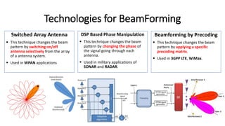
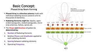
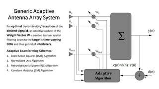
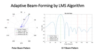
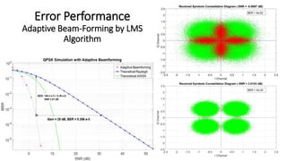
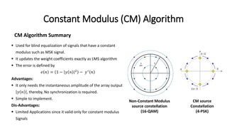
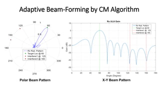
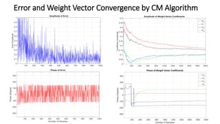
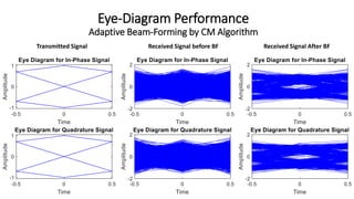
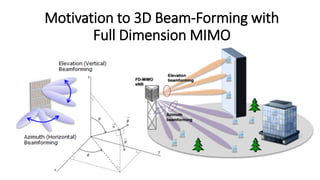
This document is a thesis submitted by Mohammed Abuibaid to Kocaeli University regarding adaptive beam-forming. It discusses various beam-forming techniques including switched array antennas, DSP-based phase manipulation, and beamforming by precoding. It also covers adaptive beamforming algorithms such as LMS, NLMS, RLS, and CM. Various beam patterns generated by these algorithms are presented. The document motivates the need for adaptive beamforming and 3D beamforming to improve energy efficiency in wireless networks.