
Recommended
Recommended
More Related Content
Similar to Fundamentals of Analog and Digital Modulation PPT.pptx
Similar to Fundamentals of Analog and Digital Modulation PPT.pptx (20)
More from SarmistaSengupta1
More from SarmistaSengupta1 (7)
Recently uploaded
Recently uploaded (20)
Fundamentals of Analog and Digital Modulation PPT.pptx
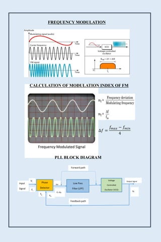
- 1. FREQUENCY MODULATION Phase Detector Low Pass Filter (LPF) Voltage Controlled Oscillator (VCO) Ver fi +fo fo Vi Fi Input Signal Forward path Feedback path vo Output Signal fo ∆𝑓 = 𝑓𝑚𝑎𝑥 − 𝑓𝑚𝑖𝑛 4 CALCULATION OF MODULATION INDEX OF FM PLL BLOCK DIAGRAM
- 2. Nyquist Sampling Theorem The sampling theorem specifies the minimum-sampling rate at which a continuous- time signal needs to be uniformly sampled so that the original signal can be completely recovered or reconstructed by these samples alone. Sampling theorem: If a continuous time signal contains no frequency components higher than W Hz, then it can be completely determined by uniform samples taken at a rate fs samples per second where fs ≥2 W FLAT-TOP SAMPLING NATURAL SAMPLING INSTANTANEOUS SAMPLING
- 3. Local Oscillator IF Amplifier & Filter Demodulator Mixer RF Amplifier Audio Amplifier AGC AMPLITUDE MODULATION AMPLITUDE DEMODULATION/ SUPER HETERODYNE RECEIVER Modulation Index (𝜇) = 𝐴𝑚 𝐴𝑐 μ = 𝐴𝑚𝑎𝑥 − 𝐴𝑚𝑖𝑛 𝐴𝑚𝑎𝑥 + 𝐴𝑚𝑖𝑛
- 4. Voltage Comparator Unipolar - Bipolar Converter CLK D f/f Q + - ∫ Analog Input Clock Input Data Output Integrator Data Input Unipolar - Bipolar Converter CLK D f/f Q + - ∫ Voltage Comparator Analog Input Clock Input Data Output Integrator Q0 Q1 Counter CLK Control Logic CLK Input CLR DELTA MODULATION (DM) ADAPTIVE DELTA MODULATION (ADM) The algorithm to control the logic is S(k) = S(k-1) d(k) + So d(k-1)
- 5. Amplitude Shift Keying (ASK) Y (t)=d(t) A Sin2πf ct CARRIER INPUT OUTPUT MODULATION INPUT CARRIER INPUT UNIPOLAR DATA STREAM ASK WAVEFORM RECTIFIER DETECTOR LPF VOLTAGE COMPATAROR INPUT ASK SIGNAL DATA OUTPUT BLOCK DIAGRAM OF ASK DEMODULATOR ASK Applications Low-frequency RF applications Wireless base stat BLOCK DIAGRAM OF FSK MODULATOR Wave form of Amplitude shift keying
- 6. Frequency Shift Keying (FSK) Y (t) =Ad(t) Sin2πf1t +Adn(t) Sin2πf2t UNIPOLAR DATA STREAM Summing amplifier CARRIER INPUT ASK1 MODULATION INPUT CARRIER INPUT INVERTED DATA INPUT ASK2 CARRIER INPUT NOT GATE ASK1 FSK ASK2 Modulator1 Modulator2 Block Diagram of Fsk modulator PLL DETECTOR LPF VOLTAGE COMPATAROR INPUT FSK SIGNAL DATA OUTPUT BLOCK DIAGRAM OF FSK DEMODULATOR Wave form of Frequency shift keying FSK Applications commonly used over telephone lines for caller ID (displaying callers' numbers) and remote metering applications.
- 7. Phase Shift Keying (PSK) The modulated carrier is given by: Binary 1: S (t) = Ac max. Cos. (2πfct) Binary 0: S (t) = Ac max. Cos. (2πfct + 180 ο) = - Ac max. Cos. (2πfct) UNI PLOAR TO BIPOLAR CONVERTER UNIPOLAR BIT STEAM CARRIER INPUT MODULATION INPUT CARRIER SIGNAL PSK OUTPUT Block Diagram of Psk modulator PSK DEMODULATOR LPF VOLTAGE COMPARATOR DIFERENTIAL BIT DECODER PSK OUTPUT DEMOD DATA Block Diagram of Psk modulator Wave form of PHASE shift keying PSK Applications It is widely used for wireless LANs, RFID and Bluetooth communication