SlideShare a Scribd company logo
8/12/2020
(C) 1
Filters
1
Unit 6: Active filters
• Filter may be classified on a number of ways.
• Analog or digital
• Passive or active
• Audio or radio frequency
http://nptel.ac.in/courses/117107094/15
2
Types of filters
• Low pass filters
• High pass filter
• Band pass filter
• Band reject filter.
• All pass filter
3
RLC Basic components
• Resistor (R)
– R
• Capacitor (C)
– Pass AC, block DC
– Impedance of capacitor = -j/ωC = -j/(2πfC)
– Capacitor current: Ic = CdV/dt
• Inductor (L)
– BlockAC, pass DC
– Impedance of inductor = jωL = j(2πfL)
– Inductor Voltage: V = LdI/dt
4
LPF (Low Pass Filter )
• Pass low frequency
• Attenuate high
frequencies
• Xc=1/2πfC
• f↓ = Xc↑
• f ↑ = Xc↓
• Cut off frequency
5
LPF
fc= 1/(2πRC)
fc=1/(2π*1.2*100μ)
fc=1326 Hz
-3dB = 0.707
6
8/12/2020
(C) 2
HPF (High Pass Filter)
• High Frequencies are pass
• Low frequencies are
attenuated
• Xc=1/2πfC
• f↓ = Xc↑
• f ↑ = Xc↓
7
HPF
fc= 1/(2πRC)
fc-=1/(2π*15*10 μ)
fc=1061 Hz
8
9
• LPF
• HPF
• BPF
• BSF
10
11
Gain on Y axis (Voltage / db)
12
8/12/2020
(C) 3
Gain / Attenuation
13
Active filters using OPAMP
• Passive filter  Attenuation due to passive
components
• Passive filters may have Loading effect
• Inductors are not used often in electronic circuits due
to their size, their susceptibility to parasitic effects
(esp. magnetic fields)
• Active filters  Required gain.
• In active filters, no loading problem as OPAMP has
high input resistance and low output resistance.
14
• A simple cascade connection
• No amplification
• No loading problem
15
ƒ = the frequency of the input signal in Hertz, (Hz)
ƒc = the cut-off frequency in Hertz, (Hz)
Gain of Active LPF is function of frequency
16
Design a low pass filter at a cutoff frequency of
1 kHz with a pass band gain of 2.
• Given fc = 1 kHz. Let C = 0.01 µF.
• Therefore, R can be obtained as
• A 20 kΩ potentiometer can be used to set the
resistance R.
• Since the pass band gain is 2, R1 and RF must
be equal. Let R1 = R2 = 10 kΩ.
17 18
8/12/2020
(C) 4
---Home work ----
•
A) Design a low pass filter at a cutoff frequency of 1
KHz with a pass band gain of 3. (assume suitable data,
if necessary).
B) For Vin = 1 Vpp, Calculate the Vout at frequencies
1) 100Hz, 2) 700Hz 3) 1000Hz 4) 1500Hz , 5) 5000Hz ,
10,000Hz , 7) 30000Hz 8) 10,000Hz,9) 1MHz 10) 10 Mhz
C) Draw the frequency response of the LPF with
a) Vout on Y- axis , b) Gain in db on Y-axis, c) Attenuation on Y-axis
use semi log paper.
19
• Design a non-inverting active low pass filter
circuit that has a gain of ten at low frequencies,
a high frequency cut-off or corner frequency of
159Hz and G =10
20
Af=10
• Fc= 159 Hz
• Assume C1=100nF
• fc= 1/(2πRC)
• R3= 10kΩ
21
Assume R1=1kΩ, So, R2 = 9 kΩ
Gain in dB= 20 log A =20 log 10 = 20dB
Check the Gain
First order high pass filter
• The cut-off frequency point for a first order
high pass filter can be found using the same
equation as that of the low pass filter
22
LPF HPF
Xc=1/2πfC
23
ƒ = the frequency of the input signal in Hertz, (Hz)
ƒc = the cut-off frequency in Hertz, (Hz)
Roll Off
• Roll off rate for first order filter
is -20dB / decade (10X)
24
8/12/2020
(C) 5
Roll-off rate
25
• Nth order filter will have a roll-off rate of 20n dB/decade.
• First-order filter = 20dB/decade.
• Second-order filter = 40dB/decade.
• Fourth-order filter =80dB/decade .
• High-order filters, such as third, fourth, and fifth-order are usually
formed by cascading together single first-order and second-order filters.
Second order Low Pass Filter
26
Second order High Pass Filter
27
Active Band Pass Filter
• Simple Active Band Pass Filter can be easily
made by cascading together a single Low Pass
Filter with a single High Pass Filter as shown
28
29
Low Pass Filter
High Pass Filter
Band Pass Filter
30
8/12/2020
(C) 6
31
Filters : Quality Factor
• Depends on the bandwidth of the pass band.
• Q = f_center/Bandwidth
32
Active Band Stop Filter
33 34
All pass filter
35
• RC= 2 π F Tan (Φ/2)
36
8/12/2020
(C) 7
HW
• Design wideband pass filter having FL= 1kHz
and FH= 6 KHz with pass band gain is 3
37
Reference:
1. George Clayton and Steve Winder, “Operational
Amplifiers”, 5th Edition Newnes.
2. Sergio Franco, “Design with Operational Amplifiers
and Analog Integrated Circuits”, Tata McGraw Hill.
3. Bali, “Linear Integrated Circuits”, Mc Graw Hill
2008.
4. Gray, Hurst, Lewise, Meyer, “Analysis & Design of
Analog Integrated Circuits”, Wiley Publications.
5. https://electronicspost.com/what-is-a-band-stop-
filter-draw-and-explain-the-frequency-response-of-a-
band-stop-filter/
38
Thank You…
- V K Bairagi
39

More Related Content

What's hot

Active filter
Active filterActive filter
Active filter
Rajput Manthan
 
Active Filters.pdf
Active Filters.pdfActive Filters.pdf
Active Filters.pdf
ArijitDhali
 
Two-stage CE amplifier
Two-stage CE amplifier Two-stage CE amplifier
Two-stage CE amplifier
mrinal mahato
 
7.Active Filters using Opamp
7.Active Filters using Opamp7.Active Filters using Opamp
7.Active Filters using Opamp
INDIAN NAVY
 
Design of FIR filters
Design of FIR filtersDesign of FIR filters
Design of FIR filters
op205
 
Dss
Dss Dss
Dss
nil65
 
IIR filter
IIR filterIIR filter
IIR filter
ssuser2797e4
 
Fir and iir filter_design
Fir and iir filter_designFir and iir filter_design
Fir and iir filter_designshrinivasgnaik
 
Design of FIR Filters
Design of FIR FiltersDesign of FIR Filters
Design of FIR Filters
Aranya Sarkar
 
RF Module Design - [Chapter 5] Low Noise Amplifier
RF Module Design - [Chapter 5]  Low Noise AmplifierRF Module Design - [Chapter 5]  Low Noise Amplifier
RF Module Design - [Chapter 5] Low Noise Amplifier
Simen Li
 
DSP_2018_FOEHU - Lec 07 - IIR Filter Design
DSP_2018_FOEHU - Lec 07 - IIR Filter DesignDSP_2018_FOEHU - Lec 07 - IIR Filter Design
DSP_2018_FOEHU - Lec 07 - IIR Filter Design
Amr E. Mohamed
 
Overlap Add, Overlap Save(digital signal processing)
Overlap Add, Overlap Save(digital signal processing)Overlap Add, Overlap Save(digital signal processing)
Overlap Add, Overlap Save(digital signal processing)
Gourab Ghosh
 
Comparison of A, B & C Power Amplifiers
Comparison of A, B & C Power AmplifiersComparison of A, B & C Power Amplifiers
Comparison of A, B & C Power Amplifiers
Jayanshu Gundaniya
 
RF Module Design - [Chapter 8] Phase-Locked Loops
RF Module Design - [Chapter 8] Phase-Locked LoopsRF Module Design - [Chapter 8] Phase-Locked Loops
RF Module Design - [Chapter 8] Phase-Locked Loops
Simen Li
 
Signal Filtering
Signal FilteringSignal Filtering
Signal Filtering
Silicon Mentor
 
Small signal analysis of bjt amplifiers
Small signal analysis of bjt amplifiersSmall signal analysis of bjt amplifiers
Small signal analysis of bjt amplifiers
PRAVEENA N G
 
Fir filter design using Frequency sampling method
Fir filter design using Frequency sampling methodFir filter design using Frequency sampling method
Fir filter design using Frequency sampling method
Sarang Joshi
 
power amplifiers
power amplifierspower amplifiers
power amplifiers
Srinivasa Rao
 
Radix-2 DIT FFT
Radix-2 DIT FFT Radix-2 DIT FFT
Radix-2 DIT FFT
Sarang Joshi
 

What's hot (20)

Filters
FiltersFilters
Filters
 
Active filter
Active filterActive filter
Active filter
 
Active Filters.pdf
Active Filters.pdfActive Filters.pdf
Active Filters.pdf
 
Two-stage CE amplifier
Two-stage CE amplifier Two-stage CE amplifier
Two-stage CE amplifier
 
7.Active Filters using Opamp
7.Active Filters using Opamp7.Active Filters using Opamp
7.Active Filters using Opamp
 
Design of FIR filters
Design of FIR filtersDesign of FIR filters
Design of FIR filters
 
Dss
Dss Dss
Dss
 
IIR filter
IIR filterIIR filter
IIR filter
 
Fir and iir filter_design
Fir and iir filter_designFir and iir filter_design
Fir and iir filter_design
 
Design of FIR Filters
Design of FIR FiltersDesign of FIR Filters
Design of FIR Filters
 
RF Module Design - [Chapter 5] Low Noise Amplifier
RF Module Design - [Chapter 5]  Low Noise AmplifierRF Module Design - [Chapter 5]  Low Noise Amplifier
RF Module Design - [Chapter 5] Low Noise Amplifier
 
DSP_2018_FOEHU - Lec 07 - IIR Filter Design
DSP_2018_FOEHU - Lec 07 - IIR Filter DesignDSP_2018_FOEHU - Lec 07 - IIR Filter Design
DSP_2018_FOEHU - Lec 07 - IIR Filter Design
 
Overlap Add, Overlap Save(digital signal processing)
Overlap Add, Overlap Save(digital signal processing)Overlap Add, Overlap Save(digital signal processing)
Overlap Add, Overlap Save(digital signal processing)
 
Comparison of A, B & C Power Amplifiers
Comparison of A, B & C Power AmplifiersComparison of A, B & C Power Amplifiers
Comparison of A, B & C Power Amplifiers
 
RF Module Design - [Chapter 8] Phase-Locked Loops
RF Module Design - [Chapter 8] Phase-Locked LoopsRF Module Design - [Chapter 8] Phase-Locked Loops
RF Module Design - [Chapter 8] Phase-Locked Loops
 
Signal Filtering
Signal FilteringSignal Filtering
Signal Filtering
 
Small signal analysis of bjt amplifiers
Small signal analysis of bjt amplifiersSmall signal analysis of bjt amplifiers
Small signal analysis of bjt amplifiers
 
Fir filter design using Frequency sampling method
Fir filter design using Frequency sampling methodFir filter design using Frequency sampling method
Fir filter design using Frequency sampling method
 
power amplifiers
power amplifierspower amplifiers
power amplifiers
 
Radix-2 DIT FFT
Radix-2 DIT FFT Radix-2 DIT FFT
Radix-2 DIT FFT
 

Similar to Active filters

09 rc filters
09 rc filters09 rc filters
09 rc filters
Sonu Rathi
 
LICA-
LICA- LICA-
Filters2
Filters2Filters2
Filters2
Krish Kan
 
Low pass filter and Integrator
Low pass filter and IntegratorLow pass filter and Integrator
Low pass filter and Integrator
George Cibi
 
unit-5 2nd part active filters by ACEIT.ppt
unit-5 2nd part active filters by ACEIT.pptunit-5 2nd part active filters by ACEIT.ppt
unit-5 2nd part active filters by ACEIT.ppt
amitthory13012003
 
Passive electrical filters
Passive electrical filtersPassive electrical filters
Passive electrical filters
Jawad Khan
 
Active filters & Low Pass Filters (LMS).ppt
Active filters & Low Pass Filters (LMS).pptActive filters & Low Pass Filters (LMS).ppt
Active filters & Low Pass Filters (LMS).ppt
AdnanZafar83
 
Exp1 (passive filter) agdon
Exp1 (passive filter)   agdonExp1 (passive filter)   agdon
Exp1 (passive filter) agdonSarah Krystelle
 

Similar to Active filters (20)

09 rc filters
09 rc filters09 rc filters
09 rc filters
 
Exp passive filter (9)
Exp passive filter (9)Exp passive filter (9)
Exp passive filter (9)
 
LICA-
LICA- LICA-
LICA-
 
Exp passive filter (6)
Exp passive filter (6)Exp passive filter (6)
Exp passive filter (6)
 
Filters2
Filters2Filters2
Filters2
 
Low pass filter and Integrator
Low pass filter and IntegratorLow pass filter and Integrator
Low pass filter and Integrator
 
unit-5 2nd part active filters by ACEIT.ppt
unit-5 2nd part active filters by ACEIT.pptunit-5 2nd part active filters by ACEIT.ppt
unit-5 2nd part active filters by ACEIT.ppt
 
Exp passive filter (3)
Exp passive filter (3)Exp passive filter (3)
Exp passive filter (3)
 
Passive electrical filters
Passive electrical filtersPassive electrical filters
Passive electrical filters
 
Exp passive filter (7)
Exp passive filter (7)Exp passive filter (7)
Exp passive filter (7)
 
Active filters & Low Pass Filters (LMS).ppt
Active filters & Low Pass Filters (LMS).pptActive filters & Low Pass Filters (LMS).ppt
Active filters & Low Pass Filters (LMS).ppt
 
Exp1 (passive filter) agdon
Exp1 (passive filter)   agdonExp1 (passive filter)   agdon
Exp1 (passive filter) agdon
 
Exp passive filter (2)
Exp passive filter (2)Exp passive filter (2)
Exp passive filter (2)
 
Exp passive filter (4)
Exp passive filter (4)Exp passive filter (4)
Exp passive filter (4)
 
Cauan
CauanCauan
Cauan
 
Balane
BalaneBalane
Balane
 
3 (3)
3 (3)3 (3)
3 (3)
 
Bani
BaniBani
Bani
 
Pula
PulaPula
Pula
 
Exp passive filter (1)
Exp passive filter (1)Exp passive filter (1)
Exp passive filter (1)
 

Recently uploaded

Automobile Management System Project Report.pdf
Automobile Management System Project Report.pdfAutomobile Management System Project Report.pdf
Automobile Management System Project Report.pdf
Kamal Acharya
 
addressing modes in computer architecture
addressing modes  in computer architectureaddressing modes  in computer architecture
addressing modes in computer architecture
ShahidSultan24
 
MCQ Soil mechanics questions (Soil shear strength).pdf
MCQ Soil mechanics questions (Soil shear strength).pdfMCQ Soil mechanics questions (Soil shear strength).pdf
MCQ Soil mechanics questions (Soil shear strength).pdf
Osamah Alsalih
 
Immunizing Image Classifiers Against Localized Adversary Attacks
Immunizing Image Classifiers Against Localized Adversary AttacksImmunizing Image Classifiers Against Localized Adversary Attacks
Immunizing Image Classifiers Against Localized Adversary Attacks
gerogepatton
 
Halogenation process of chemical process industries
Halogenation process of chemical process industriesHalogenation process of chemical process industries
Halogenation process of chemical process industries
MuhammadTufail242431
 
Event Management System Vb Net Project Report.pdf
Event Management System Vb Net  Project Report.pdfEvent Management System Vb Net  Project Report.pdf
Event Management System Vb Net Project Report.pdf
Kamal Acharya
 
AKS UNIVERSITY Satna Final Year Project By OM Hardaha.pdf
AKS UNIVERSITY Satna Final Year Project By OM Hardaha.pdfAKS UNIVERSITY Satna Final Year Project By OM Hardaha.pdf
AKS UNIVERSITY Satna Final Year Project By OM Hardaha.pdf
SamSarthak3
 
Quality defects in TMT Bars, Possible causes and Potential Solutions.
Quality defects in TMT Bars, Possible causes and Potential Solutions.Quality defects in TMT Bars, Possible causes and Potential Solutions.
Quality defects in TMT Bars, Possible causes and Potential Solutions.
PrashantGoswami42
 
Vaccine management system project report documentation..pdf
Vaccine management system project report documentation..pdfVaccine management system project report documentation..pdf
Vaccine management system project report documentation..pdf
Kamal Acharya
 
J.Yang, ICLR 2024, MLILAB, KAIST AI.pdf
J.Yang,  ICLR 2024, MLILAB, KAIST AI.pdfJ.Yang,  ICLR 2024, MLILAB, KAIST AI.pdf
J.Yang, ICLR 2024, MLILAB, KAIST AI.pdf
MLILAB
 
Student information management system project report ii.pdf
Student information management system project report ii.pdfStudent information management system project report ii.pdf
Student information management system project report ii.pdf
Kamal Acharya
 
Hybrid optimization of pumped hydro system and solar- Engr. Abdul-Azeez.pdf
Hybrid optimization of pumped hydro system and solar- Engr. Abdul-Azeez.pdfHybrid optimization of pumped hydro system and solar- Engr. Abdul-Azeez.pdf
Hybrid optimization of pumped hydro system and solar- Engr. Abdul-Azeez.pdf
fxintegritypublishin
 
Railway Signalling Principles Edition 3.pdf
Railway Signalling Principles Edition 3.pdfRailway Signalling Principles Edition 3.pdf
Railway Signalling Principles Edition 3.pdf
TeeVichai
 
DESIGN A COTTON SEED SEPARATION MACHINE.docx
DESIGN A COTTON SEED SEPARATION MACHINE.docxDESIGN A COTTON SEED SEPARATION MACHINE.docx
DESIGN A COTTON SEED SEPARATION MACHINE.docx
FluxPrime1
 
block diagram and signal flow graph representation
block diagram and signal flow graph representationblock diagram and signal flow graph representation
block diagram and signal flow graph representation
Divya Somashekar
 
power quality voltage fluctuation UNIT - I.pptx
power quality voltage fluctuation UNIT - I.pptxpower quality voltage fluctuation UNIT - I.pptx
power quality voltage fluctuation UNIT - I.pptx
ViniHema
 
TECHNICAL TRAINING MANUAL GENERAL FAMILIARIZATION COURSE
TECHNICAL TRAINING MANUAL   GENERAL FAMILIARIZATION COURSETECHNICAL TRAINING MANUAL   GENERAL FAMILIARIZATION COURSE
TECHNICAL TRAINING MANUAL GENERAL FAMILIARIZATION COURSE
DuvanRamosGarzon1
 
The Benefits and Techniques of Trenchless Pipe Repair.pdf
The Benefits and Techniques of Trenchless Pipe Repair.pdfThe Benefits and Techniques of Trenchless Pipe Repair.pdf
The Benefits and Techniques of Trenchless Pipe Repair.pdf
Pipe Restoration Solutions
 
Sachpazis:Terzaghi Bearing Capacity Estimation in simple terms with Calculati...
Sachpazis:Terzaghi Bearing Capacity Estimation in simple terms with Calculati...Sachpazis:Terzaghi Bearing Capacity Estimation in simple terms with Calculati...
Sachpazis:Terzaghi Bearing Capacity Estimation in simple terms with Calculati...
Dr.Costas Sachpazis
 
ethical hacking-mobile hacking methods.ppt
ethical hacking-mobile hacking methods.pptethical hacking-mobile hacking methods.ppt
ethical hacking-mobile hacking methods.ppt
Jayaprasanna4
 

Recently uploaded (20)

Automobile Management System Project Report.pdf
Automobile Management System Project Report.pdfAutomobile Management System Project Report.pdf
Automobile Management System Project Report.pdf
 
addressing modes in computer architecture
addressing modes  in computer architectureaddressing modes  in computer architecture
addressing modes in computer architecture
 
MCQ Soil mechanics questions (Soil shear strength).pdf
MCQ Soil mechanics questions (Soil shear strength).pdfMCQ Soil mechanics questions (Soil shear strength).pdf
MCQ Soil mechanics questions (Soil shear strength).pdf
 
Immunizing Image Classifiers Against Localized Adversary Attacks
Immunizing Image Classifiers Against Localized Adversary AttacksImmunizing Image Classifiers Against Localized Adversary Attacks
Immunizing Image Classifiers Against Localized Adversary Attacks
 
Halogenation process of chemical process industries
Halogenation process of chemical process industriesHalogenation process of chemical process industries
Halogenation process of chemical process industries
 
Event Management System Vb Net Project Report.pdf
Event Management System Vb Net  Project Report.pdfEvent Management System Vb Net  Project Report.pdf
Event Management System Vb Net Project Report.pdf
 
AKS UNIVERSITY Satna Final Year Project By OM Hardaha.pdf
AKS UNIVERSITY Satna Final Year Project By OM Hardaha.pdfAKS UNIVERSITY Satna Final Year Project By OM Hardaha.pdf
AKS UNIVERSITY Satna Final Year Project By OM Hardaha.pdf
 
Quality defects in TMT Bars, Possible causes and Potential Solutions.
Quality defects in TMT Bars, Possible causes and Potential Solutions.Quality defects in TMT Bars, Possible causes and Potential Solutions.
Quality defects in TMT Bars, Possible causes and Potential Solutions.
 
Vaccine management system project report documentation..pdf
Vaccine management system project report documentation..pdfVaccine management system project report documentation..pdf
Vaccine management system project report documentation..pdf
 
J.Yang, ICLR 2024, MLILAB, KAIST AI.pdf
J.Yang,  ICLR 2024, MLILAB, KAIST AI.pdfJ.Yang,  ICLR 2024, MLILAB, KAIST AI.pdf
J.Yang, ICLR 2024, MLILAB, KAIST AI.pdf
 
Student information management system project report ii.pdf
Student information management system project report ii.pdfStudent information management system project report ii.pdf
Student information management system project report ii.pdf
 
Hybrid optimization of pumped hydro system and solar- Engr. Abdul-Azeez.pdf
Hybrid optimization of pumped hydro system and solar- Engr. Abdul-Azeez.pdfHybrid optimization of pumped hydro system and solar- Engr. Abdul-Azeez.pdf
Hybrid optimization of pumped hydro system and solar- Engr. Abdul-Azeez.pdf
 
Railway Signalling Principles Edition 3.pdf
Railway Signalling Principles Edition 3.pdfRailway Signalling Principles Edition 3.pdf
Railway Signalling Principles Edition 3.pdf
 
DESIGN A COTTON SEED SEPARATION MACHINE.docx
DESIGN A COTTON SEED SEPARATION MACHINE.docxDESIGN A COTTON SEED SEPARATION MACHINE.docx
DESIGN A COTTON SEED SEPARATION MACHINE.docx
 
block diagram and signal flow graph representation
block diagram and signal flow graph representationblock diagram and signal flow graph representation
block diagram and signal flow graph representation
 
power quality voltage fluctuation UNIT - I.pptx
power quality voltage fluctuation UNIT - I.pptxpower quality voltage fluctuation UNIT - I.pptx
power quality voltage fluctuation UNIT - I.pptx
 
TECHNICAL TRAINING MANUAL GENERAL FAMILIARIZATION COURSE
TECHNICAL TRAINING MANUAL   GENERAL FAMILIARIZATION COURSETECHNICAL TRAINING MANUAL   GENERAL FAMILIARIZATION COURSE
TECHNICAL TRAINING MANUAL GENERAL FAMILIARIZATION COURSE
 
The Benefits and Techniques of Trenchless Pipe Repair.pdf
The Benefits and Techniques of Trenchless Pipe Repair.pdfThe Benefits and Techniques of Trenchless Pipe Repair.pdf
The Benefits and Techniques of Trenchless Pipe Repair.pdf
 
Sachpazis:Terzaghi Bearing Capacity Estimation in simple terms with Calculati...
Sachpazis:Terzaghi Bearing Capacity Estimation in simple terms with Calculati...Sachpazis:Terzaghi Bearing Capacity Estimation in simple terms with Calculati...
Sachpazis:Terzaghi Bearing Capacity Estimation in simple terms with Calculati...
 
ethical hacking-mobile hacking methods.ppt
ethical hacking-mobile hacking methods.pptethical hacking-mobile hacking methods.ppt
ethical hacking-mobile hacking methods.ppt
 

Active filters

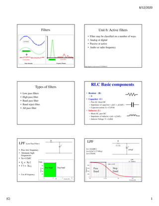
  • 1. 8/12/2020 (C) 1 Filters 1 Unit 6: Active filters • Filter may be classified on a number of ways. • Analog or digital • Passive or active • Audio or radio frequency http://nptel.ac.in/courses/117107094/15 2 Types of filters • Low pass filters • High pass filter • Band pass filter • Band reject filter. • All pass filter 3 RLC Basic components • Resistor (R) – R • Capacitor (C) – Pass AC, block DC – Impedance of capacitor = -j/ωC = -j/(2πfC) – Capacitor current: Ic = CdV/dt • Inductor (L) – BlockAC, pass DC – Impedance of inductor = jωL = j(2πfL) – Inductor Voltage: V = LdI/dt 4 LPF (Low Pass Filter ) • Pass low frequency • Attenuate high frequencies • Xc=1/2πfC • f↓ = Xc↑ • f ↑ = Xc↓ • Cut off frequency 5 LPF fc= 1/(2πRC) fc=1/(2π*1.2*100μ) fc=1326 Hz -3dB = 0.707 6
  • 2. 8/12/2020 (C) 2 HPF (High Pass Filter) • High Frequencies are pass • Low frequencies are attenuated • Xc=1/2πfC • f↓ = Xc↑ • f ↑ = Xc↓ 7 HPF fc= 1/(2πRC) fc-=1/(2π*15*10 μ) fc=1061 Hz 8 9 • LPF • HPF • BPF • BSF 10 11 Gain on Y axis (Voltage / db) 12
  • 3. 8/12/2020 (C) 3 Gain / Attenuation 13 Active filters using OPAMP • Passive filter  Attenuation due to passive components • Passive filters may have Loading effect • Inductors are not used often in electronic circuits due to their size, their susceptibility to parasitic effects (esp. magnetic fields) • Active filters  Required gain. • In active filters, no loading problem as OPAMP has high input resistance and low output resistance. 14 • A simple cascade connection • No amplification • No loading problem 15 ƒ = the frequency of the input signal in Hertz, (Hz) ƒc = the cut-off frequency in Hertz, (Hz) Gain of Active LPF is function of frequency 16 Design a low pass filter at a cutoff frequency of 1 kHz with a pass band gain of 2. • Given fc = 1 kHz. Let C = 0.01 µF. • Therefore, R can be obtained as • A 20 kΩ potentiometer can be used to set the resistance R. • Since the pass band gain is 2, R1 and RF must be equal. Let R1 = R2 = 10 kΩ. 17 18
  • 4. 8/12/2020 (C) 4 ---Home work ---- • A) Design a low pass filter at a cutoff frequency of 1 KHz with a pass band gain of 3. (assume suitable data, if necessary). B) For Vin = 1 Vpp, Calculate the Vout at frequencies 1) 100Hz, 2) 700Hz 3) 1000Hz 4) 1500Hz , 5) 5000Hz , 10,000Hz , 7) 30000Hz 8) 10,000Hz,9) 1MHz 10) 10 Mhz C) Draw the frequency response of the LPF with a) Vout on Y- axis , b) Gain in db on Y-axis, c) Attenuation on Y-axis use semi log paper. 19 • Design a non-inverting active low pass filter circuit that has a gain of ten at low frequencies, a high frequency cut-off or corner frequency of 159Hz and G =10 20 Af=10 • Fc= 159 Hz • Assume C1=100nF • fc= 1/(2πRC) • R3= 10kΩ 21 Assume R1=1kΩ, So, R2 = 9 kΩ Gain in dB= 20 log A =20 log 10 = 20dB Check the Gain First order high pass filter • The cut-off frequency point for a first order high pass filter can be found using the same equation as that of the low pass filter 22 LPF HPF Xc=1/2πfC 23 ƒ = the frequency of the input signal in Hertz, (Hz) ƒc = the cut-off frequency in Hertz, (Hz) Roll Off • Roll off rate for first order filter is -20dB / decade (10X) 24
  • 5. 8/12/2020 (C) 5 Roll-off rate 25 • Nth order filter will have a roll-off rate of 20n dB/decade. • First-order filter = 20dB/decade. • Second-order filter = 40dB/decade. • Fourth-order filter =80dB/decade . • High-order filters, such as third, fourth, and fifth-order are usually formed by cascading together single first-order and second-order filters. Second order Low Pass Filter 26 Second order High Pass Filter 27 Active Band Pass Filter • Simple Active Band Pass Filter can be easily made by cascading together a single Low Pass Filter with a single High Pass Filter as shown 28 29 Low Pass Filter High Pass Filter Band Pass Filter 30
  • 6. 8/12/2020 (C) 6 31 Filters : Quality Factor • Depends on the bandwidth of the pass band. • Q = f_center/Bandwidth 32 Active Band Stop Filter 33 34 All pass filter 35 • RC= 2 π F Tan (Φ/2) 36
  • 7. 8/12/2020 (C) 7 HW • Design wideband pass filter having FL= 1kHz and FH= 6 KHz with pass band gain is 3 37 Reference: 1. George Clayton and Steve Winder, “Operational Amplifiers”, 5th Edition Newnes. 2. Sergio Franco, “Design with Operational Amplifiers and Analog Integrated Circuits”, Tata McGraw Hill. 3. Bali, “Linear Integrated Circuits”, Mc Graw Hill 2008. 4. Gray, Hurst, Lewise, Meyer, “Analysis & Design of Analog Integrated Circuits”, Wiley Publications. 5. https://electronicspost.com/what-is-a-band-stop- filter-draw-and-explain-the-frequency-response-of-a- band-stop-filter/ 38 Thank You… - V K Bairagi 39