Downloaded 160 times

![• These overlay structures use dielectric film
materials, such as silicon nitride Si3N4 ( = 6.8),
SiO2( = 4–5), Ta2O5 ( = 20–25), Al2O3 ( = 6–10)
etc.
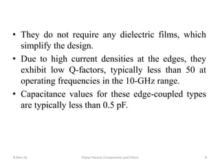
• These capacitors are used to achieve higher
values in small areas. Tolerances of these
capacitance normally run from 10% to 15%. For
better capacitance control and tuning capability,
we can use overlay configurations with tuning
elements [Figure 4.1(e)].
• Overlay capacitor values as high as 10 pF can be
realized within small areas.
8-Nov-16 Planar Passive Components and Filters 11](https://image.slidesharecdn.com/unitiii-161108180523/85/Planar-Passive-Components-and-Filters-MMICs-11-320.jpg)
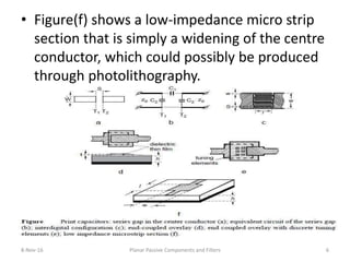
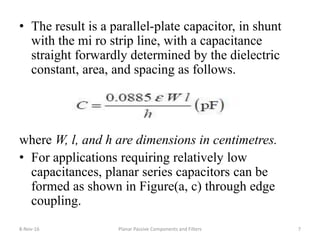
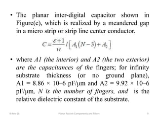
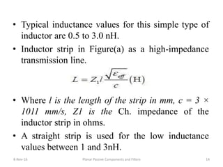
![• The simplest configuration [Figure(a)] consists of a short
section of high-impedance line that is achieved by simply
narrowing the center conductor over a short length.
where l, W, and t (conductor thickness) are in centimetres,
and kg is a correction factor to take into account the effect
of a ground plane.
for W/H>0.05 where h is the spacing from the ground
plane.
8-Nov-16 Planar Passive Components and Filters 13](https://image.slidesharecdn.com/unitiii-161108180523/85/Planar-Passive-Components-and-Filters-MMICs-13-320.jpg)
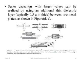
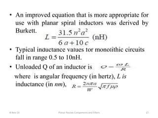
![• The meander line inductor [Figure(b)] is used to
reduce the area occupied by the element.
• In the meander inductor, adjacent conductors have
equal and opposite current flows, which reduce
the total inductance.
• A single-turn circular inductor in Figure(c) has an
inductance.
where a, W, and t are in centimetres.
8-Nov-16 Planar Passive Components and Filters 15](https://image.slidesharecdn.com/unitiii-161108180523/85/Planar-Passive-Components-and-Filters-MMICs-15-320.jpg)
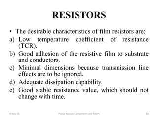
![• Spiral inductors can have a circular [Figure (d)], a
rectangular [Figure(e)], or an octagonal [Figure
(f)] configuration.
• The general relationship for a circular spiral is
where a = (D + d)/4, c = (D – d)/2, D and d are,
respectively, the maximum and minimum
diameters of a circular spiral, in millimetres, and
n is the number of turns.
8-Nov-16 Planar Passive Components and Filters 16](https://image.slidesharecdn.com/unitiii-161108180523/85/Planar-Passive-Components-and-Filters-MMICs-16-320.jpg)
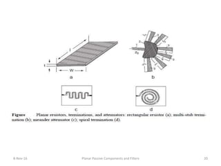
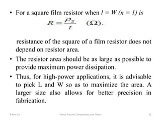
![• Planar resistors are produced by depositing films
of lossy metal on the dielectric base.
• Nichrome and tantalum are widely used due to
their good stability and low TCR.
• The resistance of a film rectangular resistor
[Figure(a)] of length l, width W, and thickness t is
given by
8-Nov-16 Planar Passive Components and Filters 21](https://image.slidesharecdn.com/unitiii-161108180523/85/Planar-Passive-Components-and-Filters-MMICs-21-320.jpg)

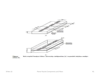
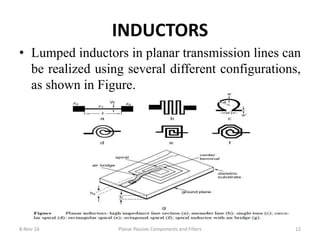
![• An end-coupled single-layer BPF provides only a
narrow band-pass.
• Medium-band and wideband filters require a
tighter coupling.
• Filters based on a two-layer configuration of
suspended strip-line [Figure] provide a compact
structure with wide pass-bands.
• End-coupled BPF, a wide range of coupling
coefficients is possible.
8-Nov-16 Planar Passive Components and Filters 47](https://image.slidesharecdn.com/unitiii-161108180523/85/Planar-Passive-Components-and-Filters-MMICs-47-320.jpg)


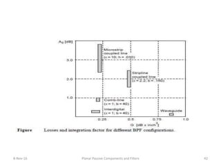
This document discusses various types of lumped elements and filters that can be used in microwave integrated circuits (MICs). It describes how lumped elements like capacitors, inductors, and resistors can be realized in planar technologies. Capacitors can be made through parallel plates, interdigital fingers, or overlay structures. Inductors can be realized as strips, meanders, or spirals. Resistors are made from deposited films. The document also covers low-pass, high-pass, band-pass, and band-stop filters that can be constructed using lumped elements or distributed elements like coupled transmission lines. Common planar filter types include stepped-impedance, parallel-coupled, end-coupled