Downloaded 300 times
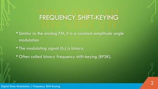
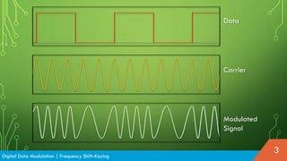
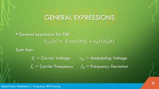

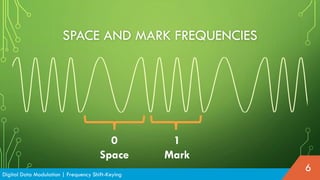
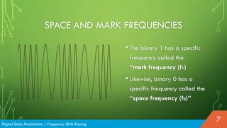
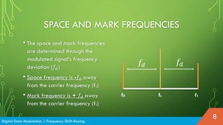
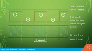
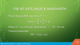
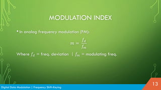

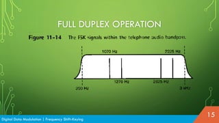
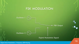
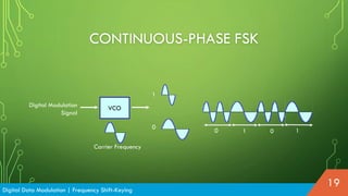
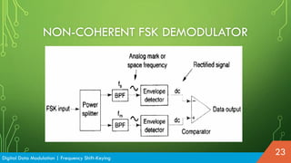
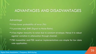

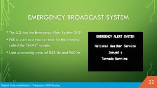


Frequency Shift-Keying (FSK) is a modulation technique similar to analog frequency modulation (FM) but used for digital data, typically represented in binary form. It utilizes specific frequencies for binary '1' (mark) and '0' (space), with expressions for modulating signals depending on the carrier and frequency deviation. While FSK has advantages such as a lower probability of error and high noise immunity, it requires larger bandwidth than other modulation techniques.


![5G Explained! A High Level Overview [Introduction]](https://cdn.slidesharecdn.com/ss_thumbnails/5gexplainedahighleveloverview-260119165306-cc137a3e-thumbnail.jpg?width=640&height=640&fit=bounds)


