Download as PDF, PPTX

![9
Limitation of Single-Carrier Transmission for High Data Rate
In order to support the symbol rate of Rs symbols per second, the minimum required bandwidth is the Nyquist bandwidth, BW =
Rs/2 [Hz].
In a single-carrier transmission, higher data rate → need wider BW (assumed that channel is perfectly compensated by equalizer).
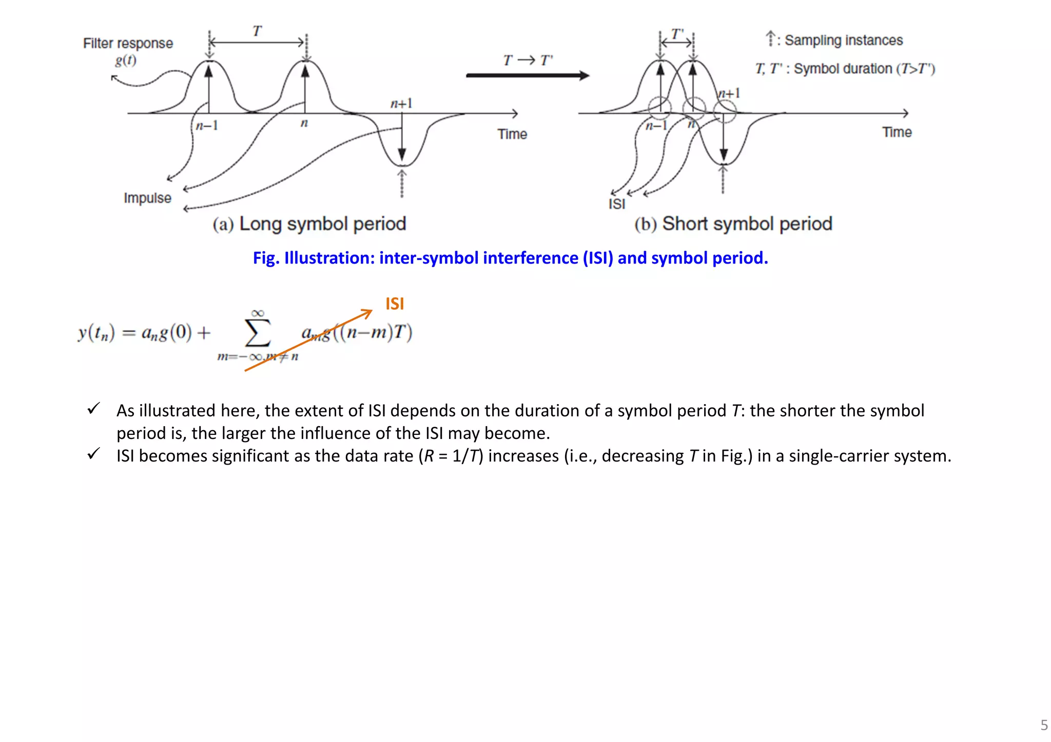
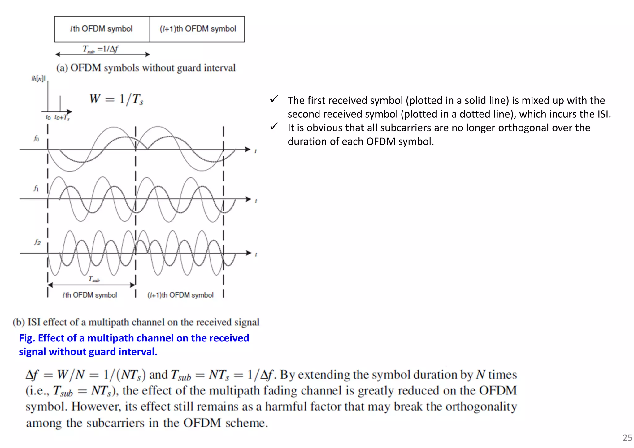
When the signal BW > coherence bandwidth in the wireless channel, the link suffers from multi-path fading, incurring ISI.
Adaptive equalizers are employed to deal with the ISI incurred by the time-varying multi-path fading channel.
The complexity of an equalizer increases with the data rate.
FIR filters with the adaptive tap coefficients that are adjusted so as to minimize the effect of ISI.
More equalizer taps are required as the ISI becomes significant.
The optimum detector for the multi-path fading channel is a maximum-likelihood sequence detector (MLSD), which bases on the
observation of a sequence of received symbols over successive symbol intervals, maximizing the posteriori probability.
(Complexity depends on the modulation order and the number of multi-paths).
Due to a memory of length L for the span of ISI, ML corresponding Euclidean distance path metrics must be evaluated to select the
best sequence in the MLSD.
6416 for L = 16 with 64-QAM at the data rate of 10 Mbps over the multi-path fading channel with a delay spread of 10 ms.
When M and L are too large, MMSE or LS equalizer, can be used.
The complexity of these suboptimum equalizers is still too enormous to be implemented as the ISI increases with the data rate.
A high data rate single-carrier transmission may not be feasible due to too much
complexity of the equalizer in the receiver.](https://image.slidesharecdn.com/introductiontoofdm-180709125941/75/Introduction-to-OFDM-9-2048.jpg)
![19
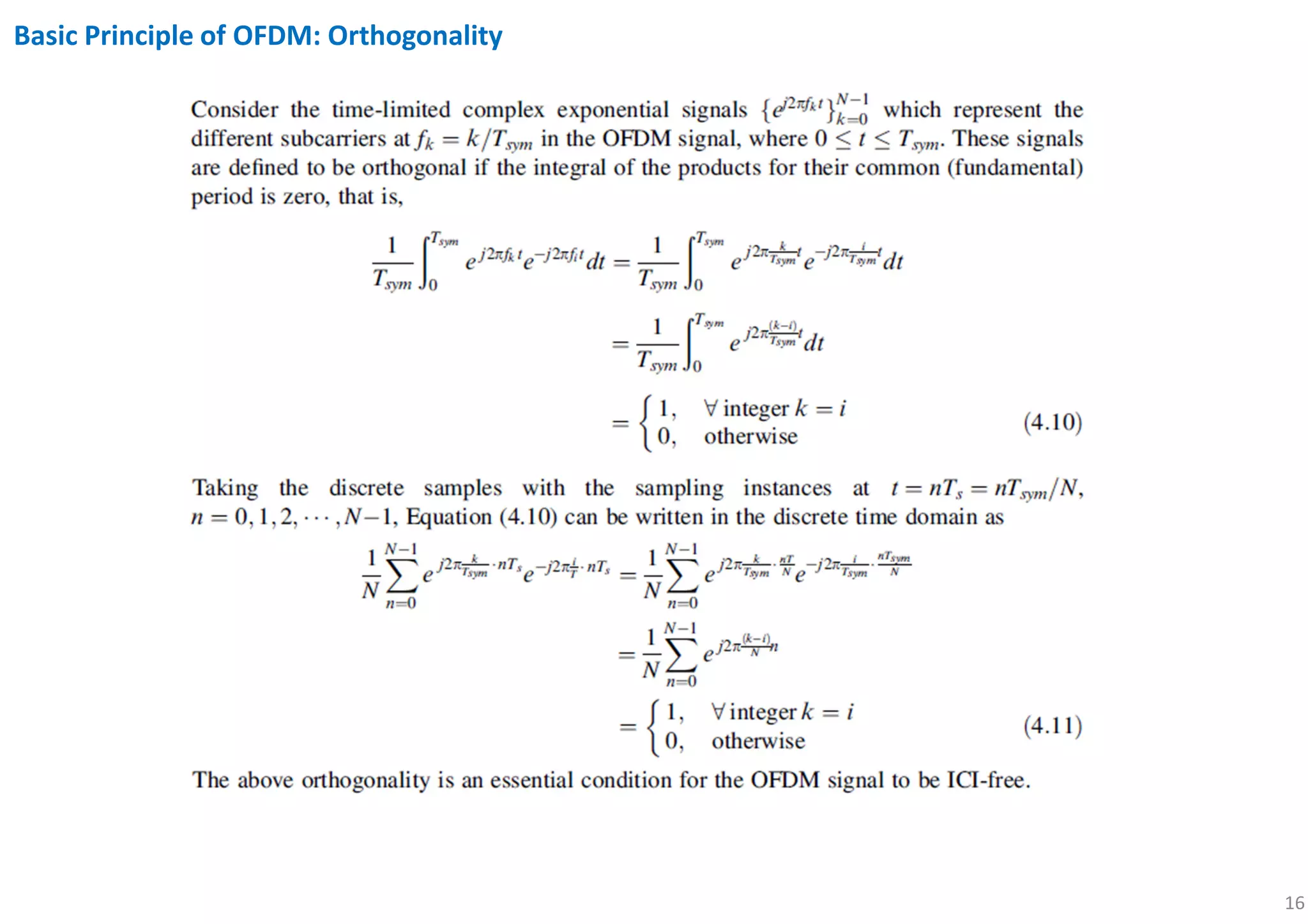
% to plot several sinusoidal signals with different frequencies/phases and their DFT sequences to check their orthogonality
% {exp(j2π*fk*t)},0≤k≤N-1,fk=k/Tsym
clear,close,clc all
T = 1.6; % period = 1.6s in equations is Tsym
ND = 1000;
nn = 0:ND;
ts = 0.002;
tt = nn*ts; % time interval 0, 0.002, 0.004..., 2 [x-axis]
Ts =0.1; % Sampling period in continuous time
M = round(Ts/ts); % Sampling period in discrete time
nns = [1:M:ND+1]; % Sampling indices
tts = (nns-1)*ts; % Sampling times
ks = [1:4 3.9 4]; % Frequency indices
tds = [0 0 0.1 0.1 0 0.15]; %delay times
K = length(ks);
for i = 1:K
k = ks(i);
td = tds(i);
x(i,:) = exp(j*2*pi*k*(tt-td)/T); % [y-axis]
if i == K
x(K,:) = [x(K,[302:end]) x(K-3,[1:301])];
endif
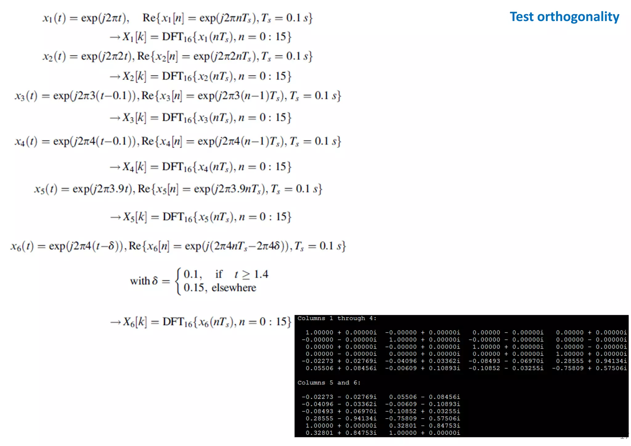
title_string = sprintf('cos(2pi*%1.1f*(t-%4.2f)/%2.1f)',k,td,T);
subplot(K,2,2*i-1); % 6 x 2
plot(tt,real(x(i,:)),'LineWidth',1); title(title_string);
hold on;
plot(tt([1 end]),[0 0],'k'); % plot([xi xf],[yi yf])
set(gca,'fontsize',10);
axis([tt([1 end]) -1.2 1.2]); % axis([xi xf yi yf])
stem(tts,real(x(i,nns)),'.','markersize',7);
endfor
N = round(T/Ts);
xn = x(:,nns(1:N));
xn*xn'/N % check orthogonality
Xk = fft(xn.').';
kk = 0:N-1;
for i = 1:K
k = ks(i);
td = tds(i);
title_string = sprintf('DFT of cos(2pi*%1.1f*(t-%4.2f)/%2.1f), t=[0:%d]*%3.2f',k,td,T,N-1,Ts);
subplot(K,2,2*i); % 6 x 2
stem(kk,abs(Xk(i,:)),'.','markersize',7); title(title_string);
set(gca,'fontsize',10,'xtick',[k]);
axis([0 N 0 20]);
endfor
https://gist.github.com/oklachumi/f41c1f5af7e9f3c1684307d5575753b1](https://image.slidesharecdn.com/introductiontoofdm-180709125941/75/Introduction-to-OFDM-19-2048.jpg)
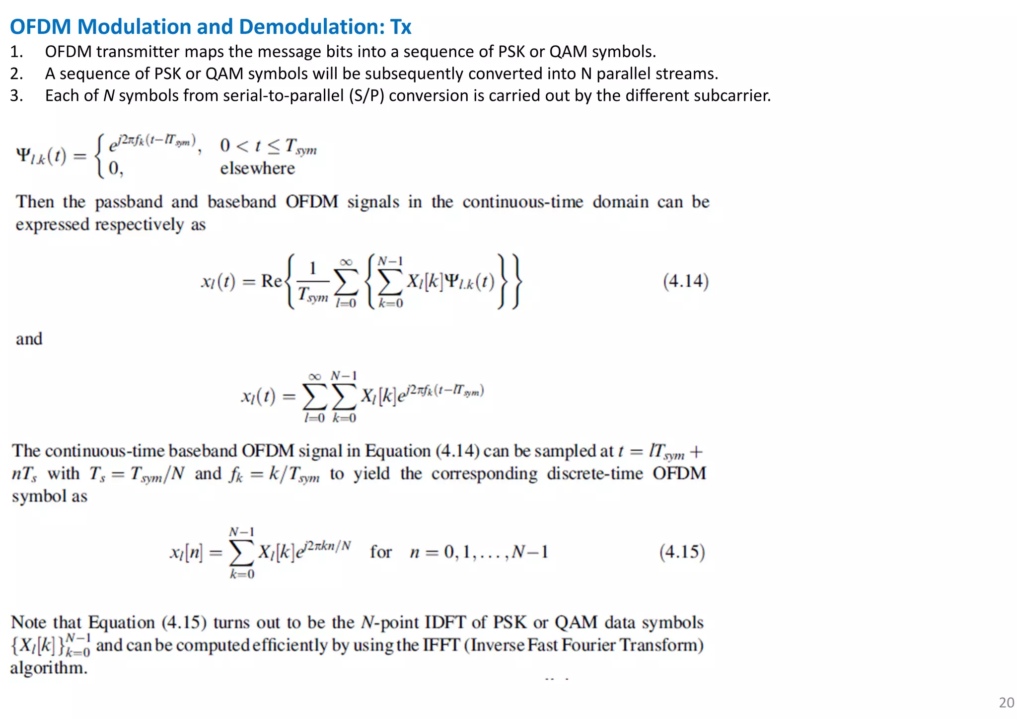
![22Fig. Illustrative block diagram of OFDM modulation and demodulation: N = 6.
continuous-time baseband OFDM signal
discrete-time OFDM symbol
The frequency-domain symbol X[k] modulates the subcarrier with a frequency of fk = k/Tsym.
Original symbol X[k] has simpling period Ts, but its length has been extended to Tsym = NTs by
transmitting N symbols in a parallel form.](https://image.slidesharecdn.com/introductiontoofdm-180709125941/75/Introduction-to-OFDM-22-2048.jpg)
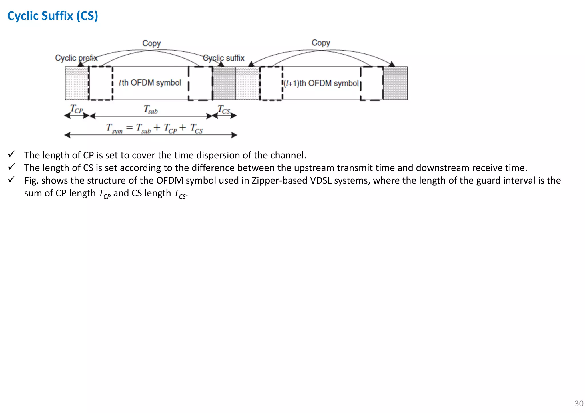
![29
Suppose:
1. CP length is set ≥ the maximum delay of the channel.
2. The FFT window start point of an OFDM symbol is determined within its CP interval (i.e., unaffected by the previous symbol).
The OFDM receiver takes the FFT of the received samples:
Fig. Frequency-domain equivalent model of OFDM system.
circular convolution!!
Insertion CP in the transmitter makes the transmit samples
circularly-convolved with the channel samples, which yields
as desired in the receiver.[ ] [ ] [ ]l l lY k H k X k=](https://image.slidesharecdn.com/introductiontoofdm-180709125941/75/Introduction-to-OFDM-29-2048.jpg)
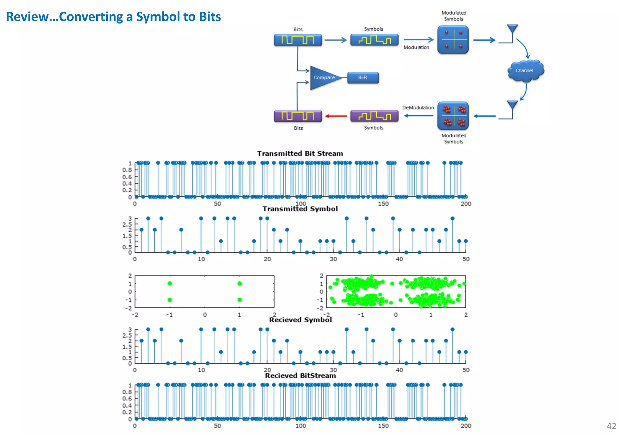
![44
clear,close,clc all
N = 1000; % # of data
mlevel = 4; % QAM = 4, 16 QAM = 16 and so on
k = log2(mlevel); % # of bits per symbol
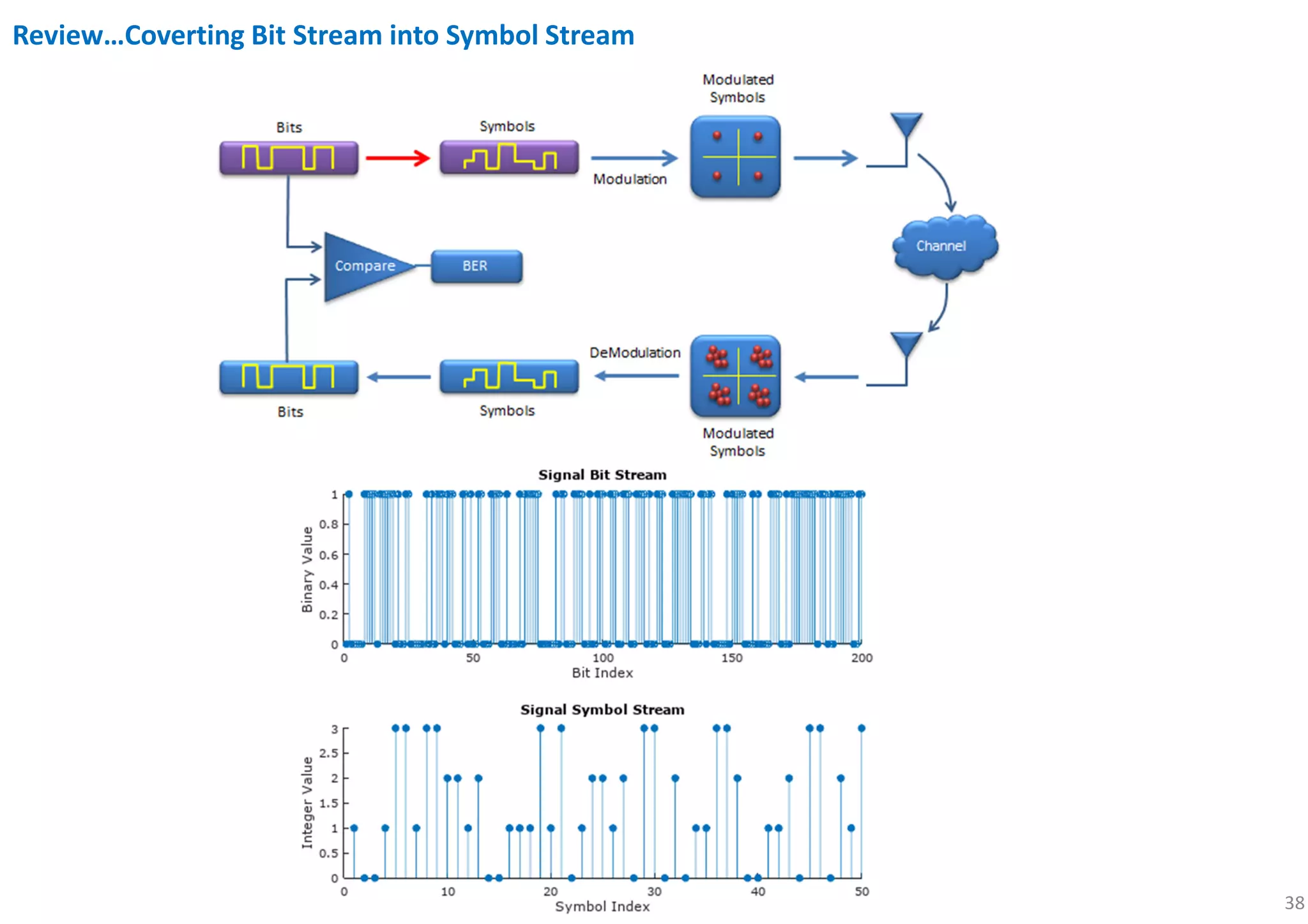
% signal generation in bit stream
x = randi([0 1],N,1); % 1000*1
% convert the bit stream into symbol stream
xsym = bi2de(reshape(x,k,length(x)/k).'); %500*1
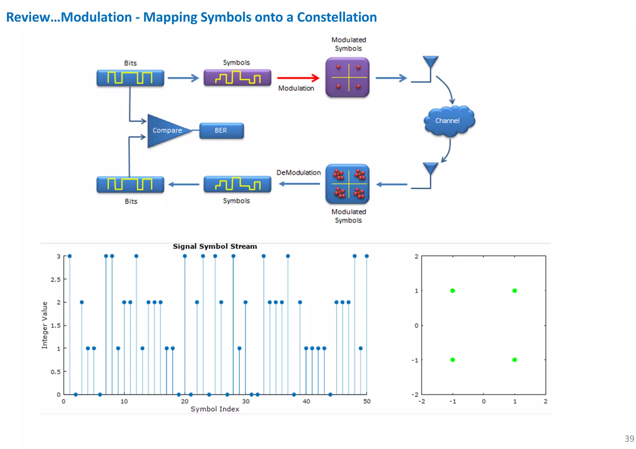
% modulation
xmod = qammod(xsym,mlevel);
Tx_x = xmod;
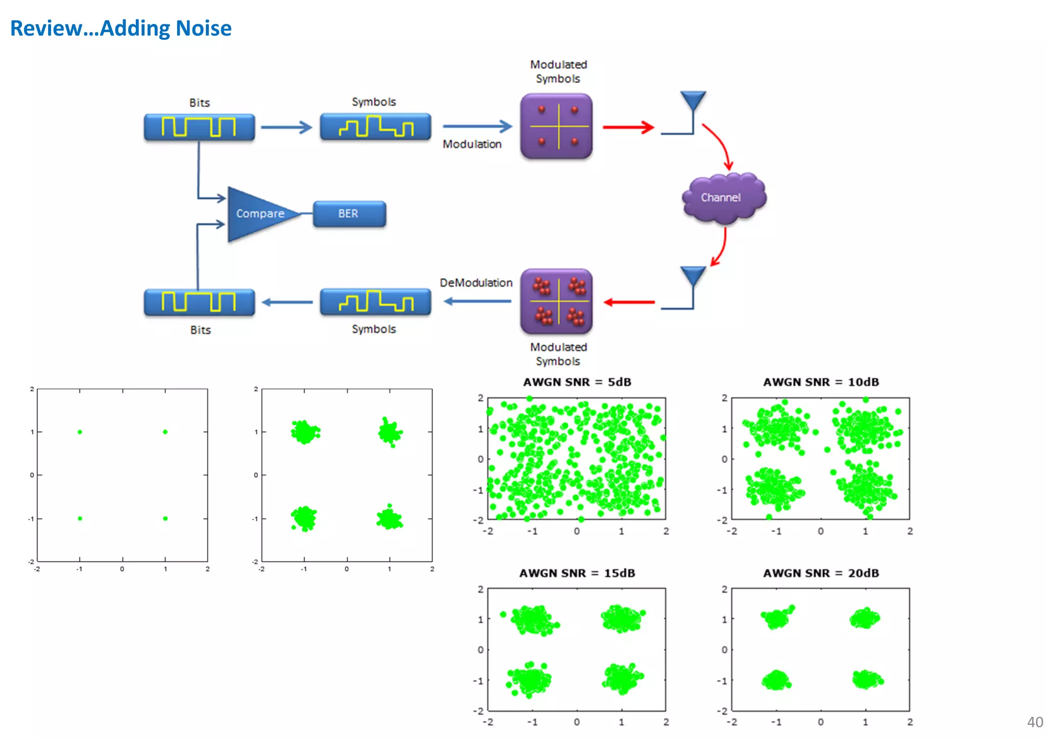
% adding AWGN
SNR = 1;
Tx_awgn = awgn(Tx_x,SNR,'measured');
% Received signal
Rx_x = Tx_awgn;
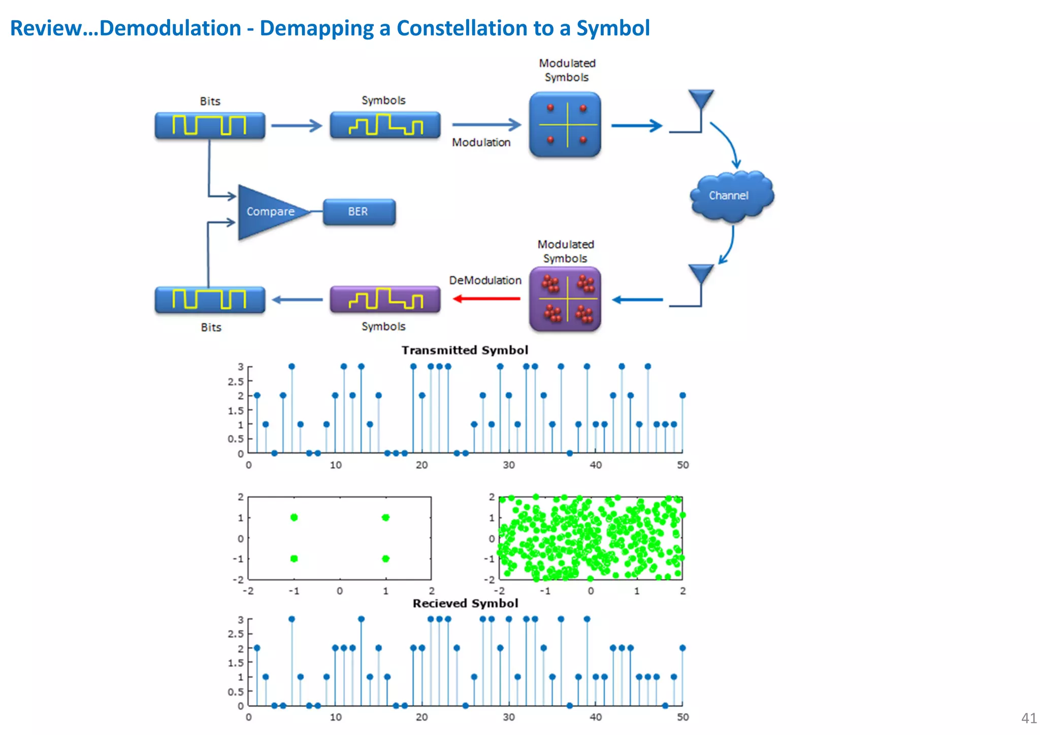
%demodulation
Rx_x_demod = qamdemod(Rx_x,mlevel);
z = de2bi(Rx_x_demod); % Convert integers to bits.
% Convert z from a matrix to a vector.
Rx_x_BitStream = reshape(z.',prod(size(z)),1);
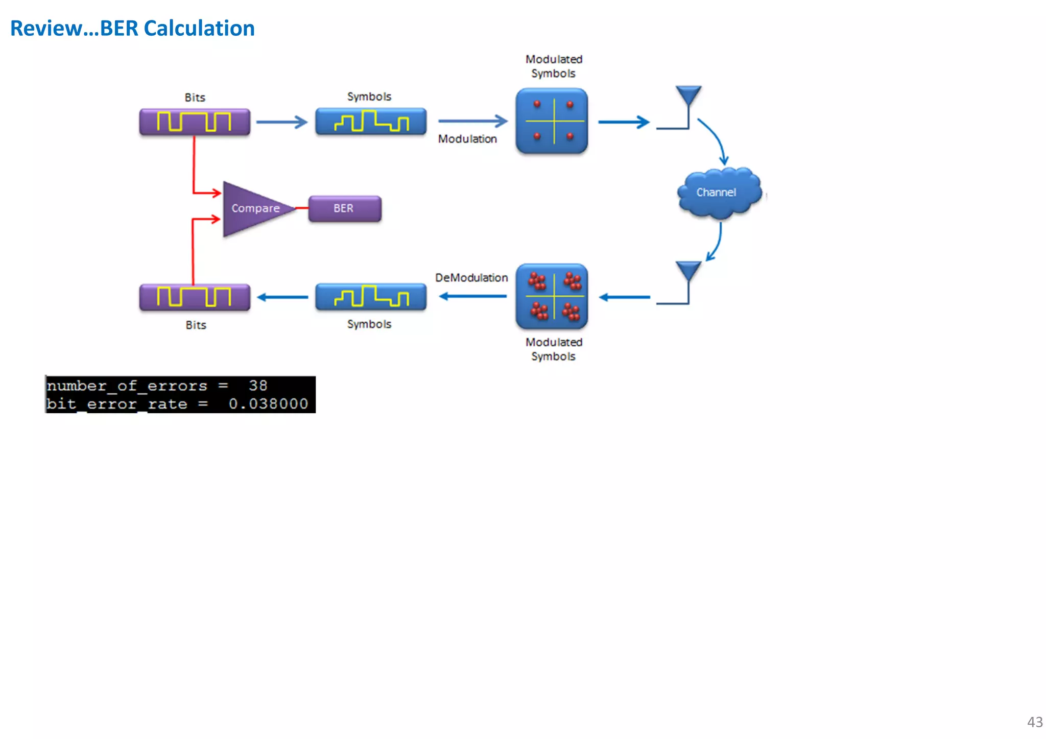
[number_of_errors, bit_error_rate] = biterr(x, Rx_x_BitStream)
%plot each steps
subplot(5,2,[1 2]); stem(x(1:200),'filled'); title('Transmitted Bit Stream');
subplot(5,2,[3 4]); stem(xsym(1:50),'filled'); title('Transmitted Symbol');
subplot(5,2,5); plot(real(Tx_x),imag(Tx_x),'go','MarkerFaceColor',[0,1,0]);
axis([-mlevel/2 mlevel/2 -mlevel/2 mlevel/2]);
subplot(5,2,6); plot(real(Rx_x),imag(Rx_x),'go','MarkerFaceColor',[0,1,0]);
axis([-mlevel/2 mlevel/2 -mlevel/2 mlevel/2]);
subplot(5,2,[7 8]); stem(Rx_x_demod(1:50),'filled'); title('Recieved Symbol');
subplot(5,2,[9 10]); stem(Rx_x_BitStream(1:200),'filled'); title('Recieved BitStream');
Review…BER Calculation](https://image.slidesharecdn.com/introductiontoofdm-180709125941/75/Introduction-to-OFDM-44-2048.jpg)
![45
clear,close,clc all
N=32; % # sub-carriers
x=randi([0 3],1,N); % data in sub-carriers
x1=qammod(x,4); % 4QAM
f=1:N; % sub-carriers freq
t=0:0.001:1-0.001; %synbol duration time
w=2*pi*f.'*t;
%w1=2*pi*(f+0.2).'*t; % sub-carriers
modulation
y1=x1*exp(j*w); % analog mod
x2=ifft(x1,N); % IFFT
plot(t,abs(y1));
hold on;
stem(0:1/N:1-1/N,abs(x2)*N,'-r')
legend('analog modulation','IDFT realization')
title('Compare between analog mod and IDFT')
%x3=fft(x2);
Review…OFDM signal modulation](https://image.slidesharecdn.com/introductiontoofdm-180709125941/75/Introduction-to-OFDM-45-2048.jpg)
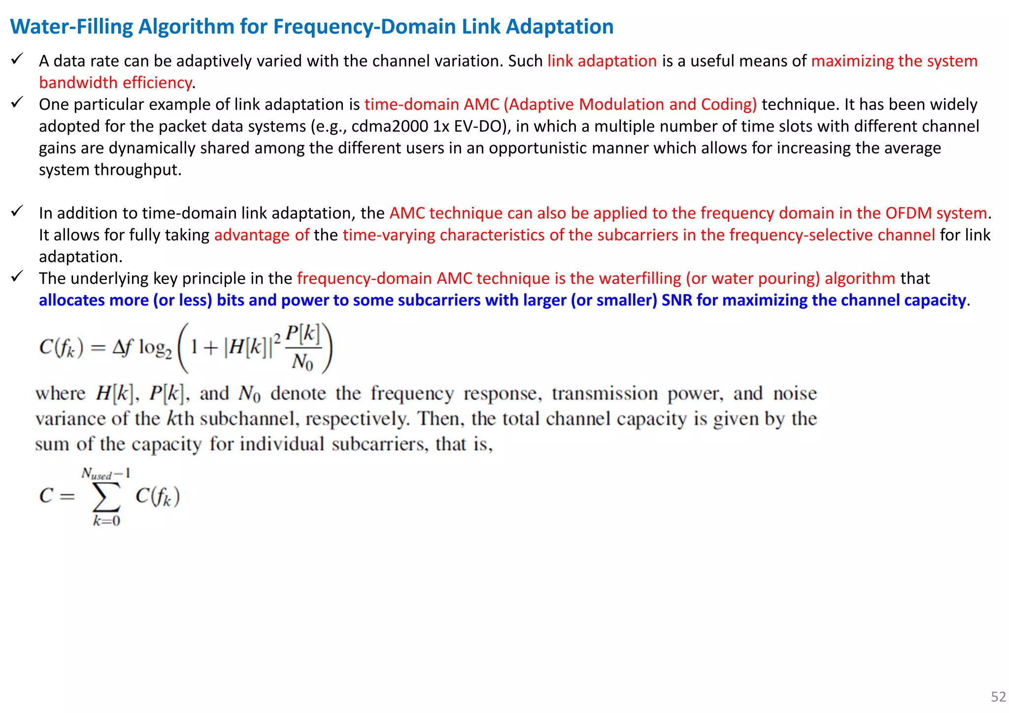
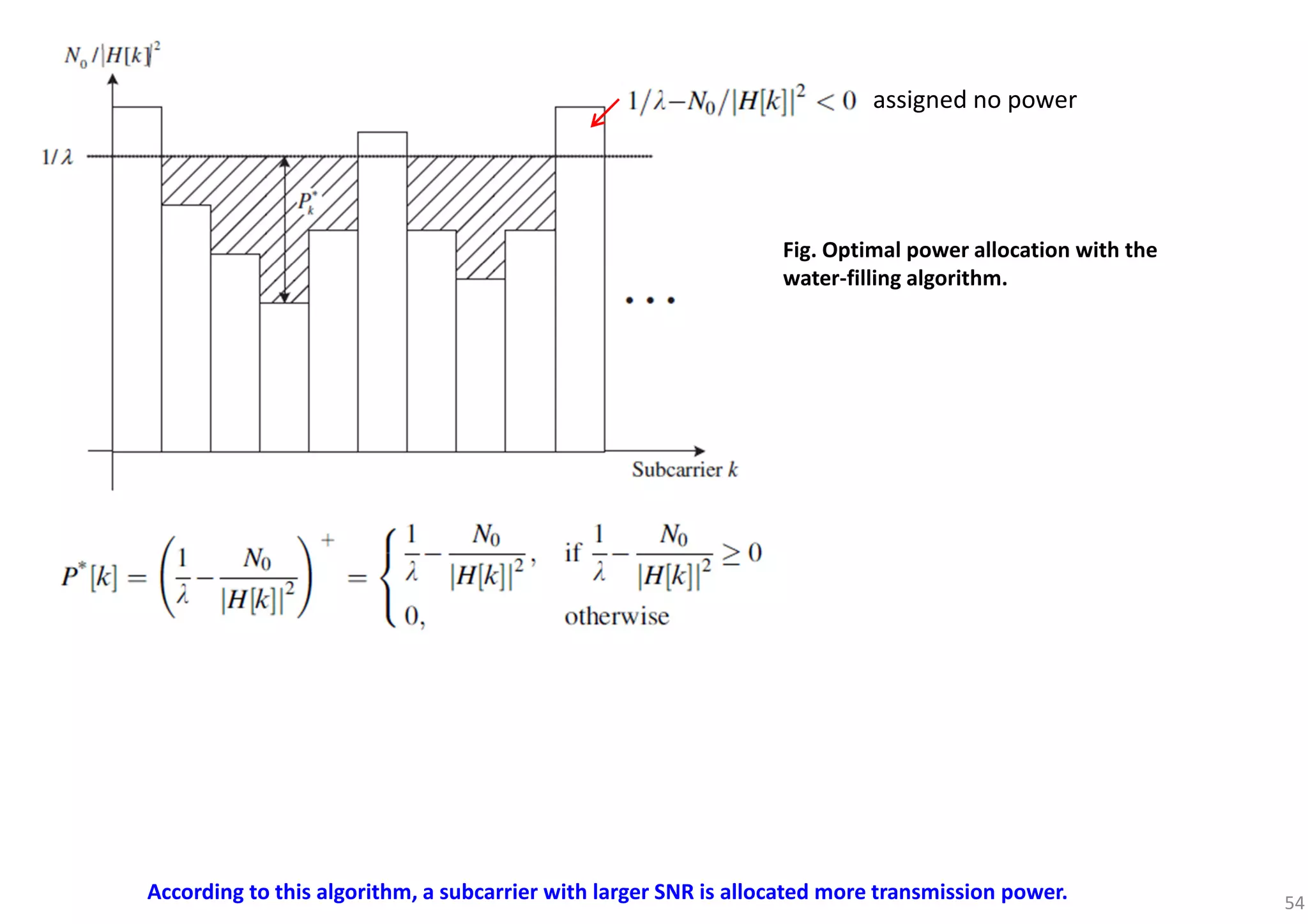
![53
coherence BW
, [ ] .
subcarrier, SNR .
f
k H k const
const
∆
⇒ ∀ =
⇒ ∀ =
≪
solution implies that the sums of power and NSR (noise-to-signal ratio) for each subcarrier must be the same for all subcarriers
According to this algorithm, a subcarrier with larger SNR is allocated more transmission power.](https://image.slidesharecdn.com/introductiontoofdm-180709125941/75/Introduction-to-OFDM-53-2048.jpg)
![63
0
1
{cos[(2 ( ) ] cos[(2 ( ) ]} 0
2
BT
k i k i k i k if f t f f t dtπ φ φ π φ φ− + − + + + + =∫
即
正交條件正交條件正交條件正交條件正交條件正交條件正交條件正交條件
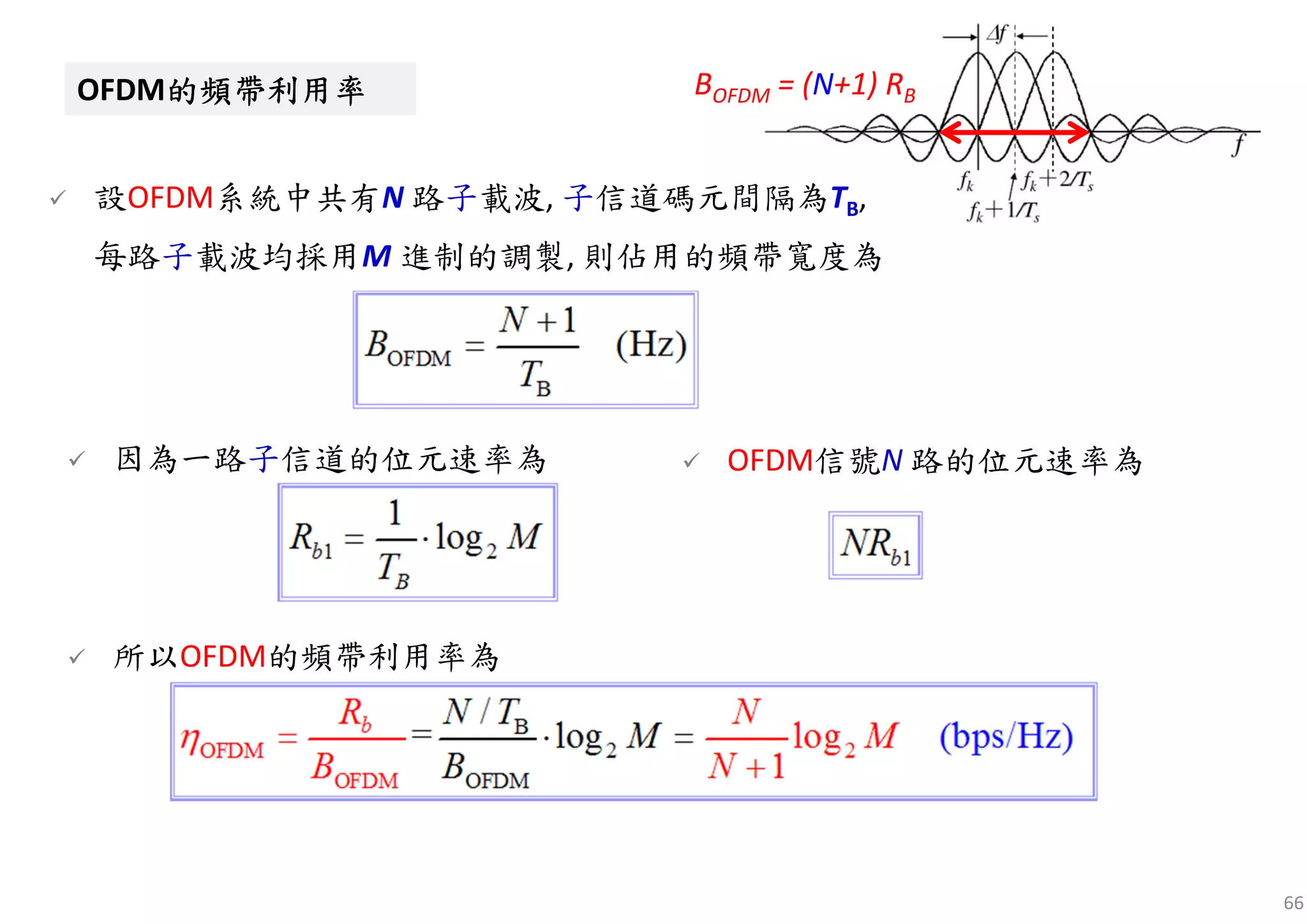
為了使這N路子信道信號在接收時能夠完全分離, 要求它們滿
足正交條件。在TB內, 任意兩個子載波都正交的條件是:
[ ] [ ]
( ) ( )
sin 2 ( ) sin 2 ( )
2 ( ) 2 ( )
sin sin
0
2 ( ) 2 ( )
k i B k i k i B k i
k i k i
k i k i
k i k i
f f T f f T
f f f f
f f f f
π φ φ π φ φ
π π
φ φ φ φ
π π
+ + + − + −
+ −
+ −
+ −
− =
+ −
積分結果為
0
cos(2 )cos(2 ) 0
BT
k k i if t f t dtπ ϕ π ϕ+ + =∫](https://image.slidesharecdn.com/introductiontoofdm-180709125941/75/Introduction-to-OFDM-63-2048.jpg)

This document provides an introduction and overview of orthogonal frequency division multiplexing (OFDM). It discusses the limitations of single-carrier transmission at high data rates due to inter-symbol interference (ISI) and the complexity of equalizers. OFDM is presented as a solution that divides the available bandwidth into multiple orthogonal subcarriers. The key concepts of OFDM covered include cyclic prefix, orthogonality of subcarriers, modulation and demodulation, and how the cyclic prefix mitigates ISI between symbols. Bit error rate simulation of an OFDM system is also demonstrated.


![Seller Deck - Presentation [Concert L2].PPTX](https://cdn.slidesharecdn.com/ss_thumbnails/sellerdeck-presentationconcertl2-251219171156-24982daf-thumbnail.jpg?width=640&height=640&fit=bounds)


