Download to read offline
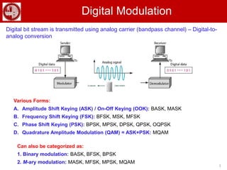
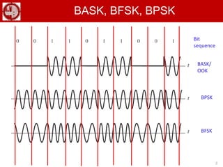
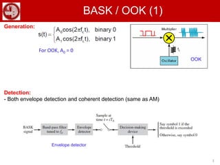
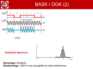

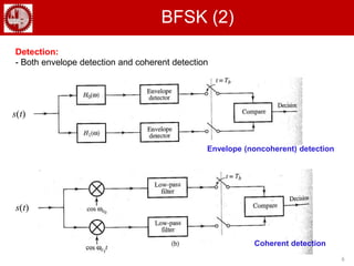
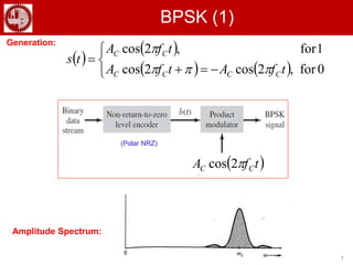
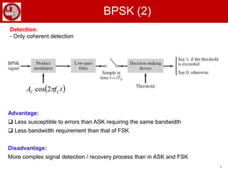
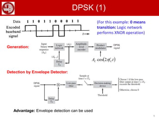
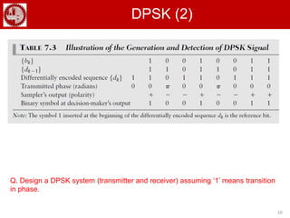
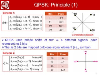
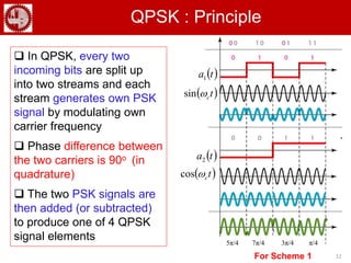
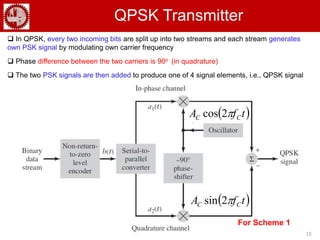
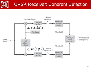
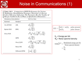
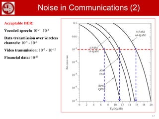

The document discusses various forms of digital modulation techniques including amplitude shift keying (ASK), frequency shift keying (FSK), phase shift keying (PSK), and quadrature amplitude modulation (QAM). It provides details on the generation and detection of binary amplitude shift keying (BASK), binary frequency shift keying (BFSK), and binary phase shift keying (BPSK). The document also discusses differential phase shift keying (DPSK) and quadrature phase shift keying (QPSK), including their principles of operation and advantages over other modulation techniques.