Downloaded 807 times
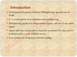
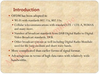

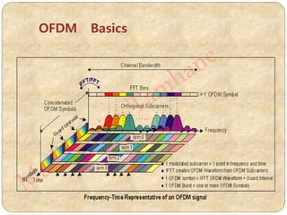
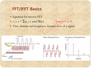
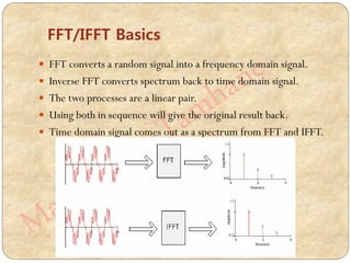
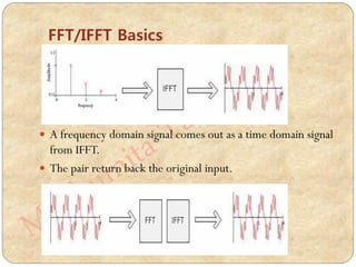

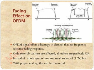
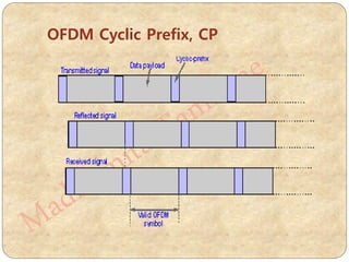

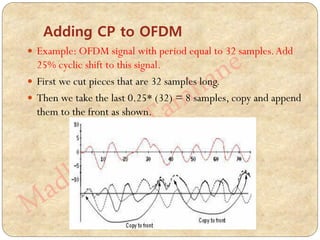
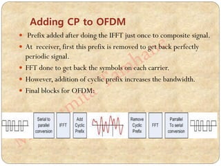
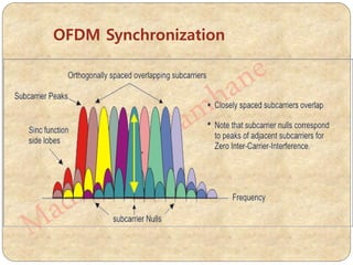
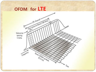


The document provides an extensive overview of Orthogonal Frequency Division Multiplexing (OFDM), detailing its principles, advantages, disadvantages, and applications in various communication standards. It explains the importance of subcarrier orthogonality, the impact of fading, the role of the cyclic prefix, and synchronization challenges associated with OFDM systems. Additionally, it includes comparisons to other multiplexing techniques and discusses the mathematical foundations of OFDM signal processing.