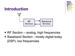
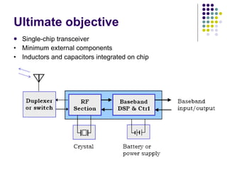
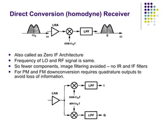
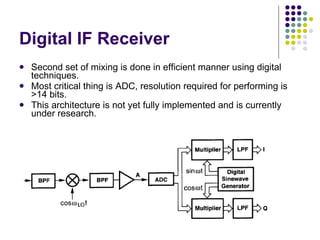
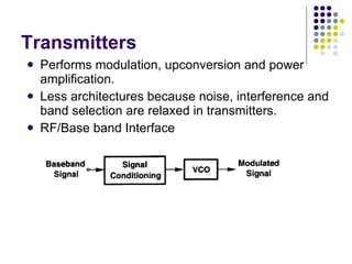
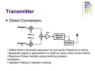
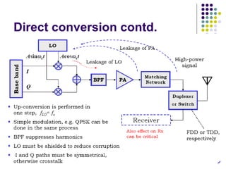
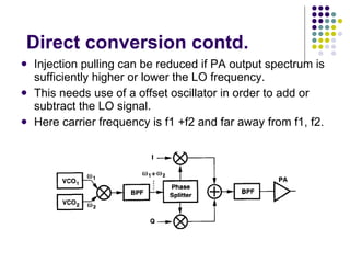
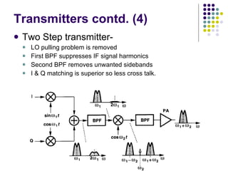
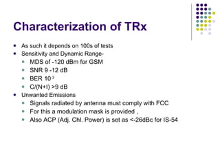
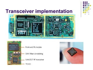
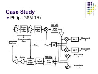
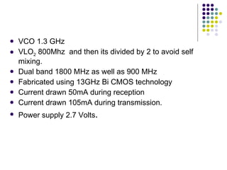
RF TRANSCEIVERS Presentation by: - Ritul Sonania 2005H124416 BITS-Pilani 24 April 2007
Contents Introduction to RF Transceivers Considerations Various Architectures Characterization of RF Transceivers Philips GSM TRx References
Introduction RF Section – analog, high frequencies Baseband Section - mostly digital today (DSP), low frequencies
Ultimate objective Single-chip transceiver •  Minimum external components •  Inductors and capacitors integrated on chip
Considerations Limited Spectrum allocation IS-54 = 30 kHz, GSM = 200 kHz Limited information rate, so coding, compression and BW efficient modulation is needed. Interference BPF order needed to select a channel (KHz) is very high (10 7 ) Dynamic range 100 dB required MDS in mVs. Large signals may be experienced so AGC is required. Power Amplifiers Consumes a lot of power and switching them on/off is required. Large current drawn from them causes battery voltage to change and creates noise so noise immunity is required.
Rx Architectures Heterodyne Receivers Concept :-
Suffers from image interference. Image can be suppressed by image reject filter. But IF can not be too large and too small  Some constraints are to be taken in to accout i.e. High IF means greater image suppression and Low IF means great suppression of nearby interferers. So Choice of IF is a trade off between selectivity and sensitivity. Possible solution to this is to use a Dual IF topology.
Dual IF topology( Heterodyne)
Direct Conversion (homodyne) Receiver Also called as Zero IF Architecture Frequency of LO and RF signal is same. So fewer components, image filtering avoided – no IR and IF filters For PM and FM downconversion requires quadrature outputs to avoid loss of information.
Homodyne contd. Issues affecting:-  Large  DC offset  can corrupt weak signal or saturate LNA (LO mixes itself), its called as self-mixing. Possible Soln. DC-free encoding and exploiting idle time intervals. Flicker noise  (1/f) be difficult to distinguish from signal (because working on zero frequency. Channel selection  with LPF, easy to integrate, (noise-linearity-power tradeoff are critical)
Homodyne contd. Qudrature generation is implemented by shifting LO phase by 90 degrees and this causes  I/Q Mismatch  while quadrature conversion phase and gain error occurs resulting in bad constellations resulting in wrong recovered information signal. Possible solution – use of signal processing techniques.
Digital IF Receiver Second set of mixing is done in efficient manner using digital techniques. Most critical thing is ADC, resolution required for performing is >14 bits. This architecture is not yet fully implemented and is currently under research.
Transmitters Performs modulation, upconversion and power amplification. Less architectures because noise, interference and band selection are relaxed in transmitters. RF/Base band Interface
Transmitter Direct Conversion- Called direct conversion because LO and carrier frequency is same. Baseband signal is generated in tx itself so mixer noise is less critical. Maximum Power transfer using matching network. Drawback- Injection Pulling or Injection Locking
Direct conversion contd.
Direct conversion contd. Injection pulling can be reduced if PA output spectrum is sufficiently higher or lower the LO frequency. This needs use of a offset oscillator in order to add or subtract the LO signal. Here carrier frequency is f1 +f2 and far away from f1, f2.
Transmitters contd. (4) Two Step transmitter- LO pulling problem is removed First BPF suppresses IF signal harmonics Second BPF removes unwanted sidebands I & Q matching is superior so less cross talk.
Characterization of TRx As such it depends on 100s of tests Sensitivity and Dynamic Range- MDS of -120 dBm for GSM SNR 9 -12 dB BER 10 -3 C/(N+I) >9 dB Unwanted Emissions Signals radiated by antenna must comply with FCC For this a modulation mask is provided , Also ACP (Adj. Chl. Power) is set as <-26dBc for IS-54
Transceiver implementation
Case Study Philips GSM TRx
VCO 1.3 GHz VLO 2  800Mhz  and then its divided by 2 to avoid self mixing. Dual band 1800 MHz as well as 900 MHz Fabricated using 13GHz Bi CMOS technology Current drawn 50mA during reception Current drawn 105mA during transmission. Power supply 2.7 Volts .
References “ RF Microelectronics”, Behzad Razavi “ Radio Frequency Integrated Circuits and Technologies”, Springer RF Transceiver Front Ends, Philips Semiconductors CTO/AST UAA3537EDGE Transceiver, www.semiconductors.philips.com

RF Transceivers

  • 1.
    RF TRANSCEIVERS Presentationby: - Ritul Sonania 2005H124416 BITS-Pilani 24 April 2007
  • 2.
    Contents Introduction toRF Transceivers Considerations Various Architectures Characterization of RF Transceivers Philips GSM TRx References
  • 3.
    Introduction RF Section– analog, high frequencies Baseband Section - mostly digital today (DSP), low frequencies
  • 4.
    Ultimate objective Single-chiptransceiver • Minimum external components • Inductors and capacitors integrated on chip
  • 5.
    Considerations Limited Spectrumallocation IS-54 = 30 kHz, GSM = 200 kHz Limited information rate, so coding, compression and BW efficient modulation is needed. Interference BPF order needed to select a channel (KHz) is very high (10 7 ) Dynamic range 100 dB required MDS in mVs. Large signals may be experienced so AGC is required. Power Amplifiers Consumes a lot of power and switching them on/off is required. Large current drawn from them causes battery voltage to change and creates noise so noise immunity is required.
  • 6.
    Rx Architectures HeterodyneReceivers Concept :-
  • 7.
    Suffers from imageinterference. Image can be suppressed by image reject filter. But IF can not be too large and too small Some constraints are to be taken in to accout i.e. High IF means greater image suppression and Low IF means great suppression of nearby interferers. So Choice of IF is a trade off between selectivity and sensitivity. Possible solution to this is to use a Dual IF topology.
  • 8.
    Dual IF topology(Heterodyne)
  • 9.
    Direct Conversion (homodyne)Receiver Also called as Zero IF Architecture Frequency of LO and RF signal is same. So fewer components, image filtering avoided – no IR and IF filters For PM and FM downconversion requires quadrature outputs to avoid loss of information.
  • 10.
    Homodyne contd. Issuesaffecting:- Large DC offset can corrupt weak signal or saturate LNA (LO mixes itself), its called as self-mixing. Possible Soln. DC-free encoding and exploiting idle time intervals. Flicker noise (1/f) be difficult to distinguish from signal (because working on zero frequency. Channel selection with LPF, easy to integrate, (noise-linearity-power tradeoff are critical)
  • 11.
    Homodyne contd. Qudraturegeneration is implemented by shifting LO phase by 90 degrees and this causes I/Q Mismatch while quadrature conversion phase and gain error occurs resulting in bad constellations resulting in wrong recovered information signal. Possible solution – use of signal processing techniques.
  • 12.
    Digital IF ReceiverSecond set of mixing is done in efficient manner using digital techniques. Most critical thing is ADC, resolution required for performing is >14 bits. This architecture is not yet fully implemented and is currently under research.
  • 13.
    Transmitters Performs modulation,upconversion and power amplification. Less architectures because noise, interference and band selection are relaxed in transmitters. RF/Base band Interface
  • 14.
    Transmitter Direct Conversion-Called direct conversion because LO and carrier frequency is same. Baseband signal is generated in tx itself so mixer noise is less critical. Maximum Power transfer using matching network. Drawback- Injection Pulling or Injection Locking
  • 15.
  • 16.
    Direct conversion contd.Injection pulling can be reduced if PA output spectrum is sufficiently higher or lower the LO frequency. This needs use of a offset oscillator in order to add or subtract the LO signal. Here carrier frequency is f1 +f2 and far away from f1, f2.
  • 17.
    Transmitters contd. (4)Two Step transmitter- LO pulling problem is removed First BPF suppresses IF signal harmonics Second BPF removes unwanted sidebands I & Q matching is superior so less cross talk.
  • 18.
    Characterization of TRxAs such it depends on 100s of tests Sensitivity and Dynamic Range- MDS of -120 dBm for GSM SNR 9 -12 dB BER 10 -3 C/(N+I) >9 dB Unwanted Emissions Signals radiated by antenna must comply with FCC For this a modulation mask is provided , Also ACP (Adj. Chl. Power) is set as <-26dBc for IS-54
  • 19.
  • 20.
  • 21.
    VCO 1.3 GHzVLO 2 800Mhz and then its divided by 2 to avoid self mixing. Dual band 1800 MHz as well as 900 MHz Fabricated using 13GHz Bi CMOS technology Current drawn 50mA during reception Current drawn 105mA during transmission. Power supply 2.7 Volts .
  • 22.
    References “ RFMicroelectronics”, Behzad Razavi “ Radio Frequency Integrated Circuits and Technologies”, Springer RF Transceiver Front Ends, Philips Semiconductors CTO/AST UAA3537EDGE Transceiver, www.semiconductors.philips.com