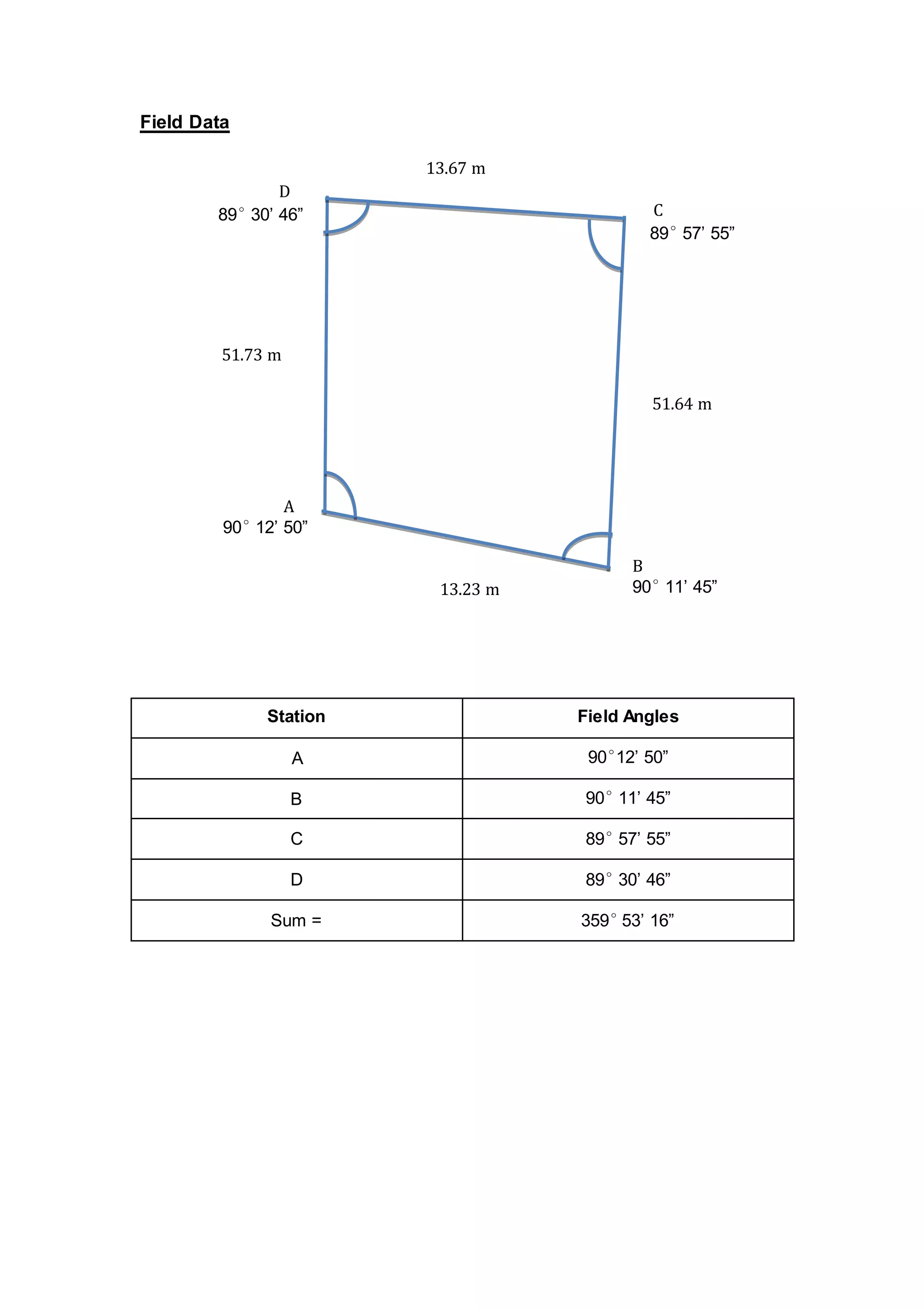
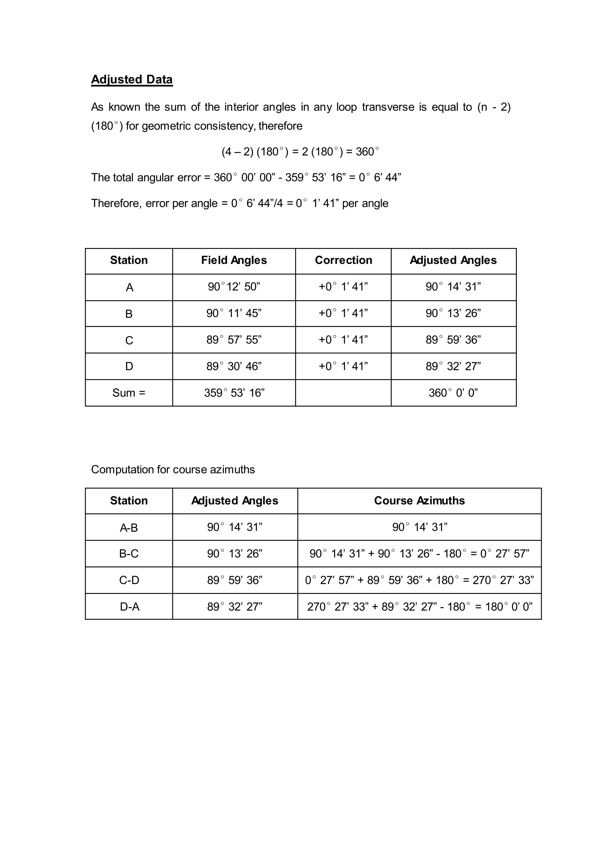
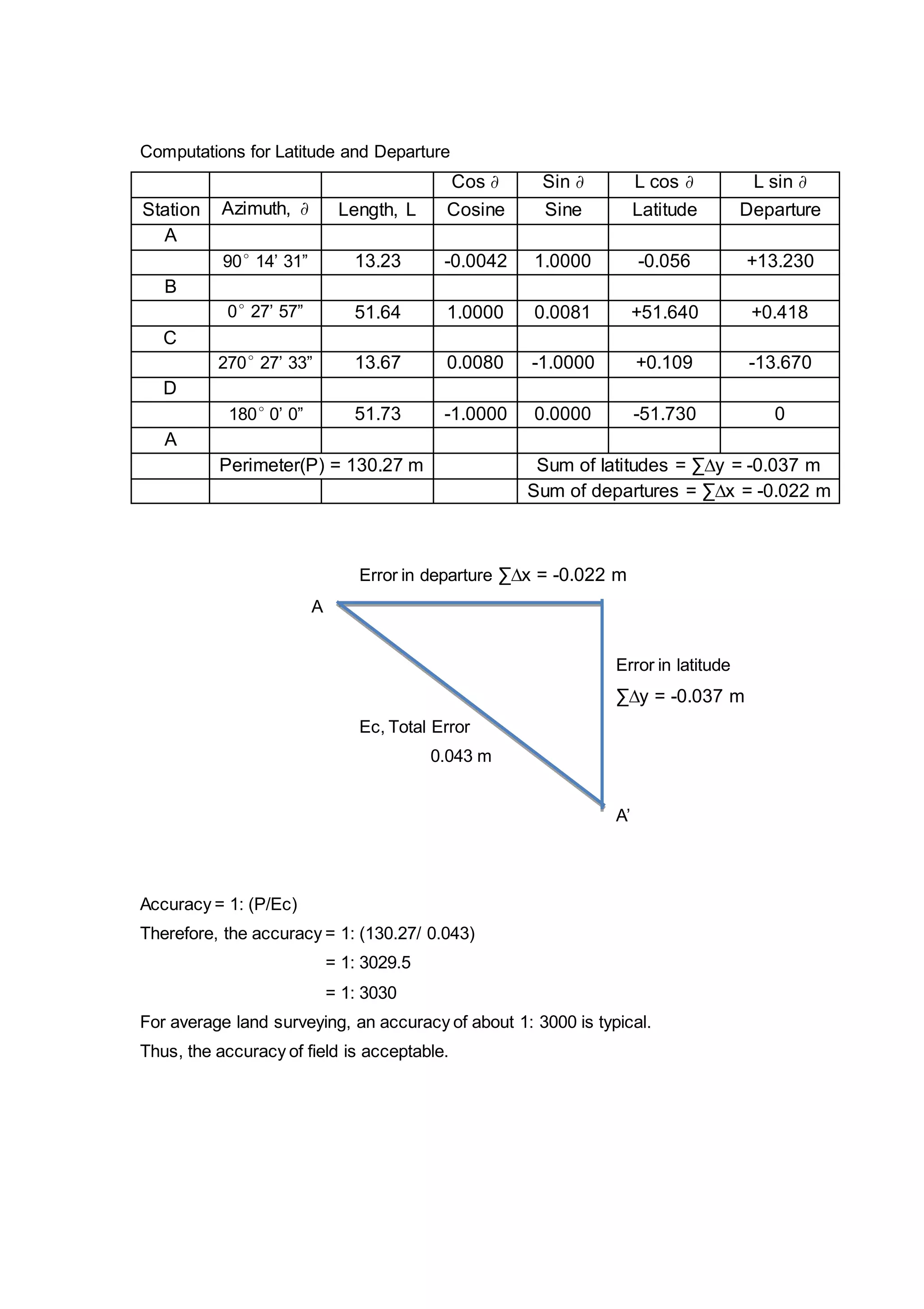
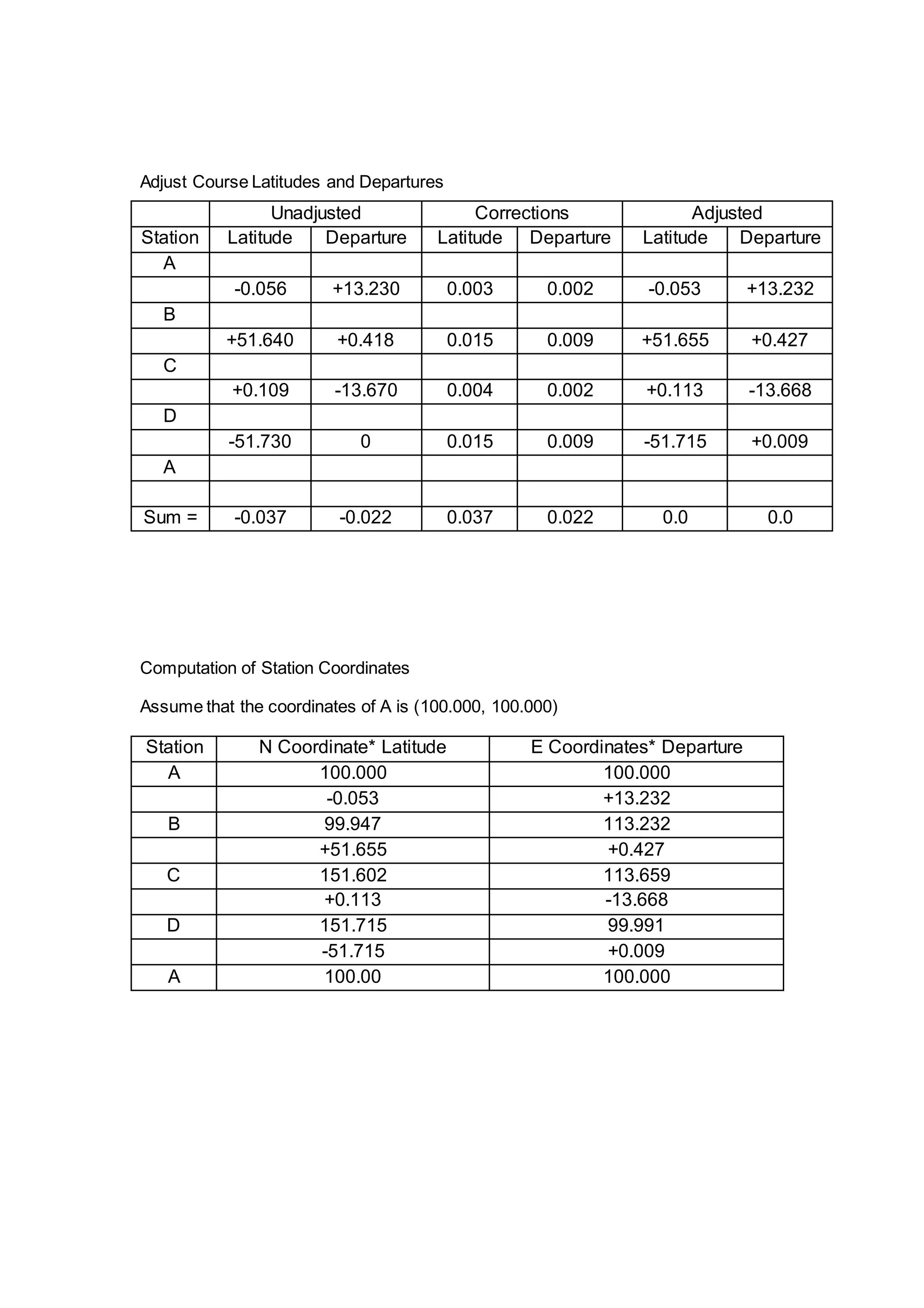
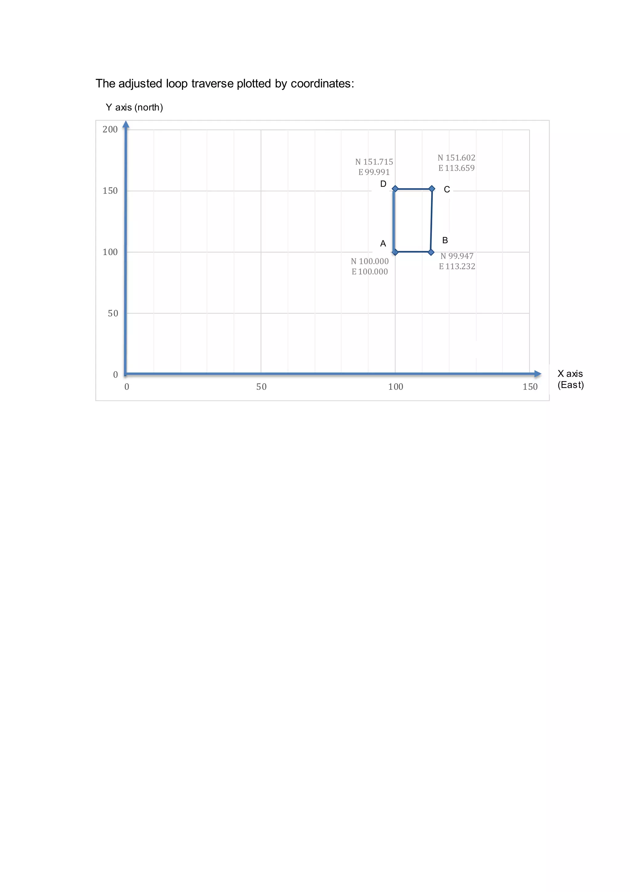
SCHOOL OF ARCHITECTURAL, 
BUILDING & 
DESIGN 
BACHELOR OF QUANTITY SURVEYING (HONOURS) 
AUGUST 2014 
[QSB 60203] SITE SURVEYING 
Fieldwork 2 
Group Member: Eley Chong Shu Hui 0319458 
Melvin Lim 0315772 
Moy Chin Hoong 0314014 
Muhammad Hakim 0310371 
Lecturer : CHAI VOON CHIET
Contents 
Contents Pages 
Objective 1 
Introduction to auto level 2 
Field Data 3 
Adjusted Data 4-7 
Summary 8
Objectives 
 To allow us to have a better understanding or knowledge about the process 
of using the instrument (Theodolite) rather than learning from a video in class. 
 To enable us to have the experience in using theodolite such as setting up, 
collaborating, calculating and recording data. 
 To enable us to know the methods to measure horizontal angles between 
lines. 
 To allow us to learn more about the life being a quantity surveyor. 
 To allow us to experience and expose to the actual working environment in 
site such as working under the hot weather. 
 To allow us to have the teamwork while carrying out the fieldwork. 
 To enable us to learn how to analyze the data collected. 
 To allow us to understand how to distribute different types of error from the 
data collected on field. 
 To enable us to have the knowledge in reading the positions on ranging rods. 
 To enable us to have a basic knowledge on how to set up the points. 
 To allow us to have the ability to undertake the site measurements and 
calculations. 
 To enable us to know the precautions should be taken while using Theodolite.
Introduction to theodolite 
A theodolite is a precision instrument for measuring angles in the horizontal and 
vertical planes. Theodolites are used mainly for surveying applications, and have 
been adapted for specialized purposes in fields like meteorology and rocket 
launch technology. A modern theodolite consists of a movable telescope mounted 
within two perpendicular axes, the horizontal or trunnion axis, and the vertical axis. 
When the telescope is pointed at a target object, the angle of each of these axes can 
be measured with great precision, typically to seconds of arc. 
Theodolites may be either transit or non-transit. Transit theodolites are those in 
which the telescope can be inverted in the vertical plane, whereas the rotation in the 
same plane is restricted to a semi-circle for non-transit theodolites. Some types of 
transit theodolites do not allow the measurement of vertical angles. 
The builder's level is sometimes mistaken for a transit theodolite, but it measures 
neither horizontal nor vertical angles. It uses a spirit level to set a telescope level to 
define a line of sight along a horizontal plane. 
Electronic Theodolite
Field Data 
D 
89° 30’ 46” 
A 
51.73 m 
90° 12’ 50” 
C 
89° 57’ 55” 
51.64 m 
B 
90° 11’ 45” 
13.67 m 
13.23 m 
Station Field Angles 
A 90°12’ 50” 
B 90° 11’ 45” 
C 89° 57’ 55” 
D 89° 30’ 46” 
Sum = 359° 53’ 16”
Adjusted Data 
As known the sum of the interior angles in any loop transverse is equal to (n - 2) 
(180°) for geometric consistency, therefore 
(4 – 2) (180°) = 2 (180°) = 360° 
The total angular error = 360° 00’ 00” - 359° 53’ 16” = 0° 6’ 44” 
Therefore, error per angle = 0° 6’ 44”/4 = 0° 1’ 41” per angle 
Station Field Angles Correction Adjusted Angles 
A 90°12’ 50” +0° 1’ 41” 90° 14’ 31” 
B 90° 11’ 45” +0° 1’ 41” 90° 13’ 26” 
C 89° 57’ 55” +0° 1’ 41” 89° 59’ 36” 
D 89° 30’ 46” +0° 1’ 41” 89° 32’ 27” 
Sum = 359° 53’ 16” 360° 0’ 0” 
Computation for course azimuths 
Station Adjusted Angles Course Azimuths 
A-B 90° 14’ 31” 90° 14’ 31” 
B-C 90° 13’ 26” 90° 14’ 31” + 90° 13’ 26” - 180° = 0° 27’ 57” 
C-D 89° 59’ 36” 0° 27’ 57” + 89° 59’ 36” + 180° = 270° 27’ 33” 
D-A 89° 32’ 27” 270° 27’ 33” + 89° 32’ 27” - 180° = 180° 0’ 0”
Computations for Latitude and Departure 
Cos ∂ Sin ∂ L cos ∂ L sin ∂ 
Station Azimuth, ∂ Length, L Cosine Sine Latitude Departure 
A 
90° 14’ 31” 13.23 -0.0042 1.0000 -0.056 +13.230 
B 
0° 27’ 57” 51.64 1.0000 0.0081 +51.640 +0.418 
C 
270° 27’ 33” 13.67 0.0080 -1.0000 +0.109 -13.670 
D 
180° 0’ 0” 51.73 -1.0000 0.0000 -51.730 0 
A 
Perimeter(P) = 130.27 m Sum of latitudes = ΣΔy = -0.037 m 
Sum of departures = ΣΔx = -0.022 m 
Error in departure ΣΔx = -0.022 m 
A 
Error in latitude 
ΣΔy = -0.037 m 
Ec, Total Error 
0.043 m 
A’ 
Accuracy = 1: (P/Ec) 
Therefore, the accuracy = 1: (130.27/ 0.043) 
= 1: 3029.5 
= 1: 3030 
For average land surveying, an accuracy of about 1: 3000 is typical. 
Thus, the accuracy of field is acceptable.
Adjust Course Latitudes and Departures 
Unadjusted Corrections Adjusted 
Station Latitude Departure Latitude Departure Latitude Departure 
A 
-0.056 +13.230 0.003 0.002 -0.053 +13.232 
B 
+51.640 +0.418 0.015 0.009 +51.655 +0.427 
C 
+0.109 -13.670 0.004 0.002 +0.113 -13.668 
D 
-51.730 0 0.015 0.009 -51.715 +0.009 
A 
Sum = -0.037 -0.022 0.037 0.022 0.0 0.0 
Computation of Station Coordinates 
Assume that the coordinates of A is (100.000, 100.000) 
Station N Coordinate* Latitude E Coordinates* Departure 
A 100.000 100.000 
-0.053 +13.232 
B 99.947 113.232 
+51.655 +0.427 
C 151.602 113.659 
+0.113 -13.668 
D 151.715 99.991 
-51.715 +0.009 
A 100.00 100.000
The adjusted loop traverse plotted by coordinates: 
Y axis (north) 
C 
D 
A B 
N 100.000 
E 100.000 
N 151.602 
E 113.659 
N 99.947 
E 113.232 
N 151.715 
E 99.991 
200 
150 
100 
50 
0 
0 50 100 150 
X axis 
(East)
Summary 
A theodolite is a precision instrument for measuring angles in the horizontal and 
vertical planes. Theodolites are used mainly for surveying applications, and have 
been adapted for specialized purposes in fields like meteorology and rocket launch 
technology. We were assigned to use this instrument for angle calculation. In this 
experienced fieldwork, we needed more than 2 hours to complete the angle 
calculation. The first thing we did was setting up the instrument. We leveled the 
theodolite before we took the measurement. We took extra time to do that because 
to stabilize the instrument was a bit hard. 
Firstly, the theodolite is placed at station A and need to adjust the theodolite until it is 
in horizontal level. Then, the station A, B, C, D must be stated on the site to form a 
loop traverse by using the small stones. We use theodolite to measure the angles of 
four stations as our field data. During measurement, the vertical and horizontal 
angles will be shown on the digital readout panel. Everything went well but the 
readings were imperfect so we had to do some distribution error. 
Our total angular for the loop traverse is 359° 53’ 16” and the total angular error is 
about 0° 6’ 44”, therefore for each angle, it has 0° 1’ 41” error in angle. Before adjust 
the readings we get, the accuracy (1:3000) is important to be calculated to ensure 
the error of closure and accuracy are acceptable. Fortunately, the accuracy is about 
1: 3030 that is a typical accuracy for average land surveying. 
The field data is adjusted and the coordinates of four stations are stated at the graph 
with assuming the coordinates of station A is (100.000, 100.000).

Fieldwork 2

  • 1.
    SCHOOL OF ARCHITECTURAL, BUILDING & DESIGN BACHELOR OF QUANTITY SURVEYING (HONOURS) AUGUST 2014 [QSB 60203] SITE SURVEYING Fieldwork 2 Group Member: Eley Chong Shu Hui 0319458 Melvin Lim 0315772 Moy Chin Hoong 0314014 Muhammad Hakim 0310371 Lecturer : CHAI VOON CHIET
  • 2.
    Contents Contents Pages Objective 1 Introduction to auto level 2 Field Data 3 Adjusted Data 4-7 Summary 8
  • 3.
    Objectives  Toallow us to have a better understanding or knowledge about the process of using the instrument (Theodolite) rather than learning from a video in class.  To enable us to have the experience in using theodolite such as setting up, collaborating, calculating and recording data.  To enable us to know the methods to measure horizontal angles between lines.  To allow us to learn more about the life being a quantity surveyor.  To allow us to experience and expose to the actual working environment in site such as working under the hot weather.  To allow us to have the teamwork while carrying out the fieldwork.  To enable us to learn how to analyze the data collected.  To allow us to understand how to distribute different types of error from the data collected on field.  To enable us to have the knowledge in reading the positions on ranging rods.  To enable us to have a basic knowledge on how to set up the points.  To allow us to have the ability to undertake the site measurements and calculations.  To enable us to know the precautions should be taken while using Theodolite.
  • 4.
    Introduction to theodolite A theodolite is a precision instrument for measuring angles in the horizontal and vertical planes. Theodolites are used mainly for surveying applications, and have been adapted for specialized purposes in fields like meteorology and rocket launch technology. A modern theodolite consists of a movable telescope mounted within two perpendicular axes, the horizontal or trunnion axis, and the vertical axis. When the telescope is pointed at a target object, the angle of each of these axes can be measured with great precision, typically to seconds of arc. Theodolites may be either transit or non-transit. Transit theodolites are those in which the telescope can be inverted in the vertical plane, whereas the rotation in the same plane is restricted to a semi-circle for non-transit theodolites. Some types of transit theodolites do not allow the measurement of vertical angles. The builder's level is sometimes mistaken for a transit theodolite, but it measures neither horizontal nor vertical angles. It uses a spirit level to set a telescope level to define a line of sight along a horizontal plane. Electronic Theodolite
  • 5.
    Field Data D 89° 30’ 46” A 51.73 m 90° 12’ 50” C 89° 57’ 55” 51.64 m B 90° 11’ 45” 13.67 m 13.23 m Station Field Angles A 90°12’ 50” B 90° 11’ 45” C 89° 57’ 55” D 89° 30’ 46” Sum = 359° 53’ 16”
  • 6.
    Adjusted Data Asknown the sum of the interior angles in any loop transverse is equal to (n - 2) (180°) for geometric consistency, therefore (4 – 2) (180°) = 2 (180°) = 360° The total angular error = 360° 00’ 00” - 359° 53’ 16” = 0° 6’ 44” Therefore, error per angle = 0° 6’ 44”/4 = 0° 1’ 41” per angle Station Field Angles Correction Adjusted Angles A 90°12’ 50” +0° 1’ 41” 90° 14’ 31” B 90° 11’ 45” +0° 1’ 41” 90° 13’ 26” C 89° 57’ 55” +0° 1’ 41” 89° 59’ 36” D 89° 30’ 46” +0° 1’ 41” 89° 32’ 27” Sum = 359° 53’ 16” 360° 0’ 0” Computation for course azimuths Station Adjusted Angles Course Azimuths A-B 90° 14’ 31” 90° 14’ 31” B-C 90° 13’ 26” 90° 14’ 31” + 90° 13’ 26” - 180° = 0° 27’ 57” C-D 89° 59’ 36” 0° 27’ 57” + 89° 59’ 36” + 180° = 270° 27’ 33” D-A 89° 32’ 27” 270° 27’ 33” + 89° 32’ 27” - 180° = 180° 0’ 0”
  • 7.
    Computations for Latitudeand Departure Cos ∂ Sin ∂ L cos ∂ L sin ∂ Station Azimuth, ∂ Length, L Cosine Sine Latitude Departure A 90° 14’ 31” 13.23 -0.0042 1.0000 -0.056 +13.230 B 0° 27’ 57” 51.64 1.0000 0.0081 +51.640 +0.418 C 270° 27’ 33” 13.67 0.0080 -1.0000 +0.109 -13.670 D 180° 0’ 0” 51.73 -1.0000 0.0000 -51.730 0 A Perimeter(P) = 130.27 m Sum of latitudes = ΣΔy = -0.037 m Sum of departures = ΣΔx = -0.022 m Error in departure ΣΔx = -0.022 m A Error in latitude ΣΔy = -0.037 m Ec, Total Error 0.043 m A’ Accuracy = 1: (P/Ec) Therefore, the accuracy = 1: (130.27/ 0.043) = 1: 3029.5 = 1: 3030 For average land surveying, an accuracy of about 1: 3000 is typical. Thus, the accuracy of field is acceptable.
  • 8.
    Adjust Course Latitudesand Departures Unadjusted Corrections Adjusted Station Latitude Departure Latitude Departure Latitude Departure A -0.056 +13.230 0.003 0.002 -0.053 +13.232 B +51.640 +0.418 0.015 0.009 +51.655 +0.427 C +0.109 -13.670 0.004 0.002 +0.113 -13.668 D -51.730 0 0.015 0.009 -51.715 +0.009 A Sum = -0.037 -0.022 0.037 0.022 0.0 0.0 Computation of Station Coordinates Assume that the coordinates of A is (100.000, 100.000) Station N Coordinate* Latitude E Coordinates* Departure A 100.000 100.000 -0.053 +13.232 B 99.947 113.232 +51.655 +0.427 C 151.602 113.659 +0.113 -13.668 D 151.715 99.991 -51.715 +0.009 A 100.00 100.000
  • 9.
    The adjusted looptraverse plotted by coordinates: Y axis (north) C D A B N 100.000 E 100.000 N 151.602 E 113.659 N 99.947 E 113.232 N 151.715 E 99.991 200 150 100 50 0 0 50 100 150 X axis (East)
  • 10.
    Summary A theodoliteis a precision instrument for measuring angles in the horizontal and vertical planes. Theodolites are used mainly for surveying applications, and have been adapted for specialized purposes in fields like meteorology and rocket launch technology. We were assigned to use this instrument for angle calculation. In this experienced fieldwork, we needed more than 2 hours to complete the angle calculation. The first thing we did was setting up the instrument. We leveled the theodolite before we took the measurement. We took extra time to do that because to stabilize the instrument was a bit hard. Firstly, the theodolite is placed at station A and need to adjust the theodolite until it is in horizontal level. Then, the station A, B, C, D must be stated on the site to form a loop traverse by using the small stones. We use theodolite to measure the angles of four stations as our field data. During measurement, the vertical and horizontal angles will be shown on the digital readout panel. Everything went well but the readings were imperfect so we had to do some distribution error. Our total angular for the loop traverse is 359° 53’ 16” and the total angular error is about 0° 6’ 44”, therefore for each angle, it has 0° 1’ 41” error in angle. Before adjust the readings we get, the accuracy (1:3000) is important to be calculated to ensure the error of closure and accuracy are acceptable. Fortunately, the accuracy is about 1: 3030 that is a typical accuracy for average land surveying. The field data is adjusted and the coordinates of four stations are stated at the graph with assuming the coordinates of station A is (100.000, 100.000).