The document summarizes a student's fieldwork using a theodolite to conduct a traversing survey. Key details include:
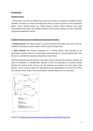
- The student conducted a closed traverse survey with 4 stations, measuring angles and lengths between stations.
- Angular errors were distributed and angles were adjusted to total 360°. Station coordinates were then computed.
- Total angular error was -0°12'20" and total linear error was 0.0668m, yielding an accuracy of 1:2700, within acceptable limits.
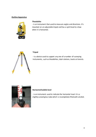
- The fieldwork helped students learn skills like setting up a theodolite, measuring angles and distances, and adjusting data.