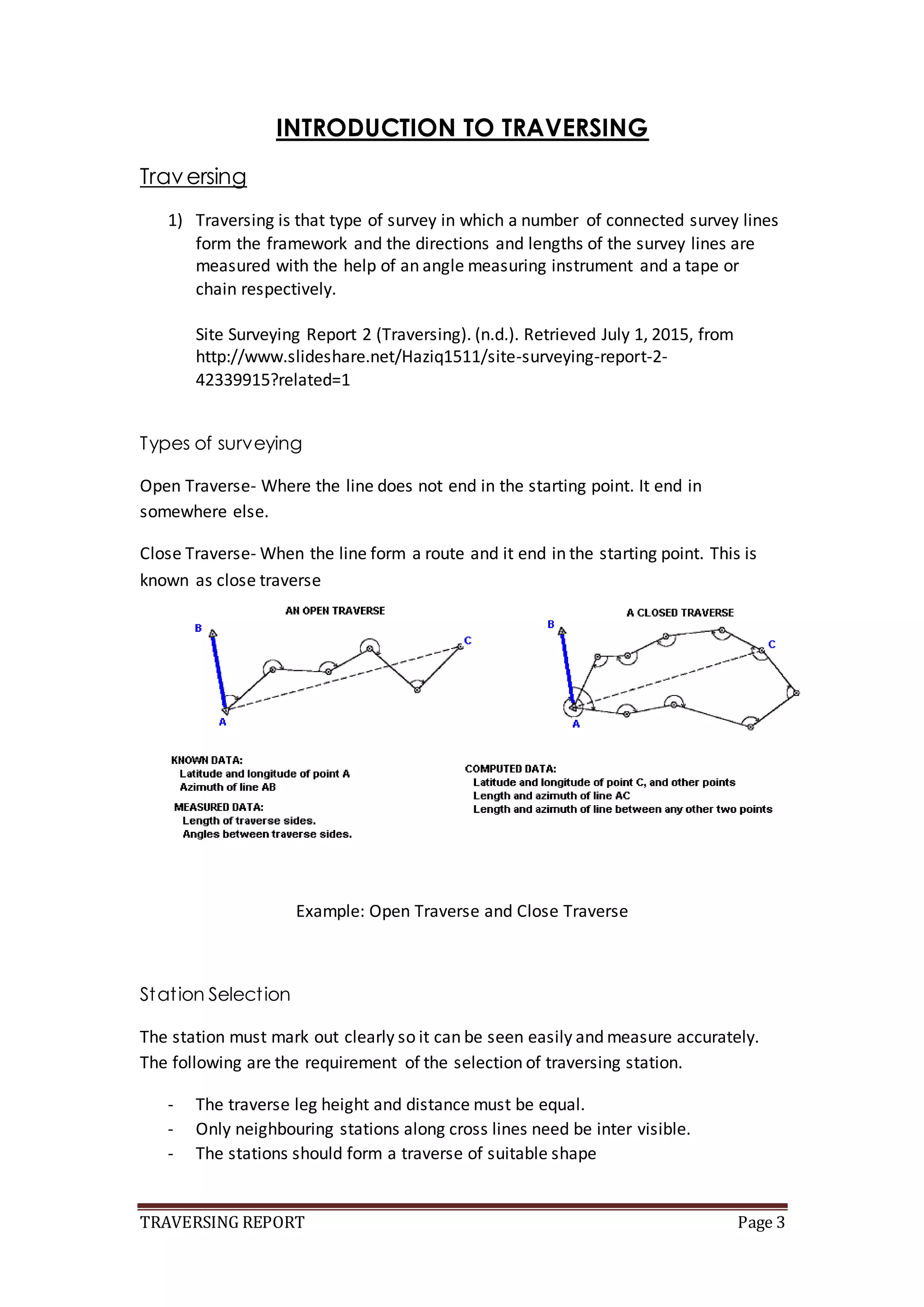
TRAVERSING REPORT Page 1
SCHOOL OF ARCHITECTURE, BUILDING AND
DESIGN
BACHELOR OF QUANTITY SURVEYING(HONOURS)
QSB 60103 – SITE SURVEYING
FIELDWORK 2nd
REPORT
TRAVERSING
MARCH SEMESTER 2015
NAME STUDENT ID MARKS
TEE SIN YI 0315689
THAN LEK MEI 0315538
THUN SHAO XUN 0315919
SHANE SIM EE HAN 0321288
TRAVERSING REPORT Page 2
TABLE OF CONTENT
CONTENT PAGE
COVER PAGE 1
TABLE OF CONTENT 2
INTRODUCTION TO TRAVERSING 3-4
OBJECTIVE 5
OUTLINE OF APPARATUS 6-9
DATA FIELD 10-15
DISCUSSION 16
CONCLUSION 17
REFERENCES 18
TRAVERSING REPORT Page 3
INTRODUCTION TO TRAVERSING
Traversing
1) Traversing is that type of survey in which a number of connected survey lines
form the framework and the directions and lengths of the survey lines are
measured with the help of an angle measuring instrument and a tape or
chain respectively.
Site Surveying Report 2 (Traversing). (n.d.). Retrieved July 1, 2015, from
http://www.slideshare.net/Haziq1511/site-surveying-report-2-
42339915?related=1
Types of surveying
Open Traverse- Where the line does not end in the starting point. It end in
somewhere else.
Close Traverse- When the line form a route and it end in the starting point. This is
known as close traverse
Example: Open Traverse and Close Traverse
Station Selection
The station must mark out clearly so it can be seen easily and measure accurately.
The following are the requirement of the selection of traversing station.
- The traverse leg height and distance must be equal.
- Only neighbouring stations along cross lines need be inter visible.
- The stations should form a traverse of suitable shape
TRAVERSING REPORT Page 4
Azimuth
The angular distance usually measured clockwise from the north point of the horizon
to the intersection with the horizon of the vertical circle passing through a celestial
body Compare altitude (sense 3)
Bearing
A bearing is an angle less than 90° within a quadrant defined by the cardinal
directions (Penn State College of Earth and Mineral Sciences, 2014).
TRAVERSING REPORT Page 5
OBJECTIVE
• To enhance the students knowledge in traversing procedure.
• To identify the spot relative heights and possible errors occurred.
• To establish a new benchmark.
• To determine the difference in height of discrete points.
• To enable students to get hands-on experience in setting up and working
with the theodolite.
TRAVERSING REPORT Page 6
Outline of Apparatus
Theodolite
A Theodolite is an instrument for measuring both horizontal and vertical angles, as
used in triangulation networks, and geo-location work. It is a tool used in the land
surveying and engineering industry, but theodolites have been adapted for other
specialized purposes as well. Other specialized purposes make Theodolites ideal for
shop and factory floor layout of tools and fixtures. They also work well for layout for
the construction of concrete slabs, swimming pools, golf courses, landscaping, and
road design.
The horizontal accuracy of Theodolites depends on "seconds". A 2-second theodolite
is more accurate than a 5 or 9-second theodolite. If you think about the horizontal
circle that a theodolite rotates around, the circle is divided into 360 degrees. Each
degree is divided into 60 minutes, and each minute divided into 60 seconds. Think
"Degrees / Minutes / Seconds". The horizontal angle is the measure of inaccuracy
(hence accuracy) that a theodolite can horizontally measure or locate within. If a
theodolites accuracy rating is 2 seconds (written 2") then its only going to lose 2
seconds of horizontal measurement in a given distance. Generally speaking, a 9
second theodolite is for construction sites where you're working relatively up close,
say within 200 feet from the instrument. A 2 second you would work 2,000 feet
away and still work with some level of accruacy. Most building contractors, whether
residential or commercial, can use a 9 second theodolite without experiencing
problems due to accuracy. At this distance, more errors are in the form of human
errors, such as not leveling the instrument properly or taking a quick reading which
lends itself to human error.
TRAVERSING REPORT Page 7
Tripod
This levelling tripod consist of three leg. Each leg can be adjustable with any height
and also distance between the legs. This is to make sure that the levelling tripod
place horizontal.
Plumb Bob
A plumb bob or a plumet is a weight, for the most part with a pointed tip on the base,
that is suspended from a string and utilized as a vertical reference line, or plumb-line.
It is basically also known as called a "water level".
TRAVERSING REPORT Page 8
Ranging Rod
A pole for marking positions in surveying. Ranging rod can be purchase easily in
anywhere and it is made from a straight pipe.
Levelling
A leveling rod is a surveying tool used to take elevation measurements for the
purpose of profiling a section of terrain. There are a number of basic designs
available, including versions for optical and digital sighting and record keeping.
Surveying supply companies typically sell leveling rods and accessories like cases,
replacement components, and other surveying tools. Engineers, surveyors, and
members of other professions that need to perform surveys receive instruction in
the use of a leveling rod as part of their education.
This tool is also known as a level staff, a reference to the original design, which was
simply a tall staff with measurement markings. The surveyor could place the staff in
TRAVERSING REPORT Page 9
a location with a landmark of known height, perform a sighting for reference, and
then move the staff to take a series of sightings, looping back to the original site or
another known reference for confirmation at the end. While older level staffs are
still in use, modern designs are more flexible and tend to be easier to use.
TRAVERSING REPORT Page 10
DATA FIELD
ANGULARERROR &ANGLEADJUSTMENTS
The sum of the interioranglesinanylooptraverse mustequal (n-2)(180°) forgeometric
consistency,whichmeansthe sumhastobe 360°
(4-2)(180°) = 2(180°) = 360°
Total angularerror= 360°00’00’’ - 359° 41’ 20’’ = 0° 18’ 40’’
station Fieldangles correction Adjustedangles
A 89° 06’ 20’’ +4’40’’ 89° 11’ 00’’
B 90° 26’ 00’’ +4’40’’ 90° 30’ 40’’
C 88° 16’ 40’’ +4’40’’ 88° 21’ 20’’
D 91° 52’ 20’’ +4’40’’ 91° 57’ 00’’
Sum= 358° 100’ 80’’ 360° 00’ 00’’
359° 41’ 20’’
Therefore,errorperangle = 18’ 40’’ / 4 = 4’ 40’’ per angle
TRAVERSING REPORT Page 11
COURSE BEARING& AZIMUTH
89° 11’ 00’’
Azimuth N
89° 11’ 00’’
180° 00’ 00’’
+ 90° 30’ 40’’
+ 89° 11’ 00’’
359° 41’ 40’’
88° 21’ 20’’
-0° 18’ 20’’
88° 03’ 00’
+ 180° 0’ 00’’
268° 03’ 00’’
91° 57’ 00’’
+ 88° 03’ 00’’
180° 00’ 00’’
Bearing
N 89° 11’ 00’’ E
N 0° 18’ 20’’ W
S 88° 03’ 00’ W
S 0° E
90° 30’ 40’’
88° 21’ 20’’
A
B
C
D
?
TRAVERSING REPORT Page 12
COURSE LATTITUDE& DEPARTURE
Cos β Sin β Lcosβ Lsinβ
station Bearing, β Length, L cosine sine latitude departure
A N 89° 11’ 00’’ E 20.30 0.014253 0.9998984 0.2893367 20.297937
B N 0° 18’ 20’’ W 55.78 0.999985 0.0053329 55.779206 0.2974705
C S 88° 03’ 00’ W 20.57 0.034027 0.9994209 -0.6999425 -20.558087
D S 0° E 55.35 1.000000 0 -55.350000 0
152.00 0.0186002 0.0373214
Accuracy= 1 : (P/Ec), typical=1:3000
Ec = [(sum of latitude)2 + (sum of departure)2 ]1/2
= 0.042
P = 152.00
Accuracy = 1: (152.00/0.042)
= 1: 3645
∴The traversing is acceptable
TRAVERSING REPORT Page 13
Adjusted Latitude & Departure
Compass Rule:
Correction = - [∑Δy] ÷ P x L or - [∑Δx] ÷ P x L
CorrectionAB Lat=-0.0186002 ÷152.00 x20.30
= -0.0024841
CorrectionBCLat=-0.0186002 ÷152.00x 55.78
= -0.0068258
CorrectionCD Lat=-0.0186002÷152.00 x 20.57
= -0.0025171
CorrectionDA Lat=-0.0186002 ÷152.00 x 55.35
= -0.0067732
CorrectionAB Dep=-0.0373214÷152.00x20.30
=-0.0049844
CorrectionBCDep=-0.0373214÷152.00 x55.78
= -0.0136960
CorrectionCD Dep=-0.0373214÷152.00 x20.57
= -0.0050501
CorrectionDA Dep=-0.0373214÷152.00x55.35
= -0.0135904
Unadjusted Corrections Adjustments
Station Latitude Departure Latitude Departure Latitude Departure
A 0.28933 20.29794 -0.00248 -0.00498 0.28685 20.29296
B 55.77920 0.29747 -0.00683 -0.01370 55.77237 0.28377
C
-0.69994 -20.55809 -0.00252 -0.00505 -0.70245 -20.56314
D -55.35000 0 -0.00677 -0.01359 -55.35677 -0.01359
Check 0.01860 0.03732 -0.01858 -5.08272 0 0
TRAVERSING REPORT Page 14
Table & Graph of Station Coordinates
N2 = N1 + Lat1-2
E2 = E1 + Dep1-2
Where:
N2 and E2 = the Y and X coordinates of station 2
N1 and E1 = the Y and X coordinates of station 1
Lat1-2 = the latitude course 1-2
Dep1-2 = the departure course 1-2
Course Adjusted
Latitude
Adjusted
Departure
Station N Coordinate Latitude
(y-axis)
E Coordinate Departure
(x-axis)
A 100.0000(Assumed) 100.0000(Assumed)
AB 0.28685 20.29296
B 100.28685 120.29296
BC 55.77238 0.28377
C 156.05923 120.57673
CD -0.70245 -20.56314
D 155.35678 100.01359
DA -55.35677 -0.01359 A 100.0000 (Checked) 100.0000 (Checked)
TRAVERSING REPORT Page 15
TRAVERSING REPORT Page 16
DISCUSSION
Before executing the process, we need to decide where should point A, B, C and D
laid out on the site respectively. As the number of theodolite prepared was limited,
we would have to take turn as we were sharing the theodolite. Thus, we learnt from
other groups and discussed among each other as we failed for the first attempt.
This is a closed loop traverse. The angles of the theodolite must be read from left to
right in order to obtain a more accurate reading.
The total recorded angles must be 360°. However, there was some errors occurred
and the recorded angles had difference of 18’ 40’’. Thus, we had to adjust it. Lastly,
we had to tabulate data and draw graph based on the result.
TRAVERSING REPORT Page 17
CONCLUSION
According to the data obtained by using the theodolite, the angle obtained is not
exactly 360°. Hence, there are angular errors occurred and angles must be adjusted.
To adjust the angles, the amount of exceeding angles shall be divided into 4 set ups
and added or subtracted by the 4 angles obtained on site. With the data obtained,
we are able to produce this fieldwork report.
TRAVERSING REPORT Page 18
REFERENCE
1) (n.d.). Retrieved June 28, 2015, from
https://www.google.com/url?sa=i&rct=j&q=&esrc=s&source=images&cd=&c
ad=rja&uact=8&ved=0CAcQjRw&url=http://www.hayesinstrument.com/st_p
rod.html?p_prodid=2151&ei=wZ-
PVdb4O5K3uQSI6oKYAQ&bvm=bv.96783405,d.c2E&psig=AFQjCNFFHbzBaRS
pahCZwzDT3IefL-m6eA
2) Site Surveying Report 2 (Traversing). (n.d.). Retrieved July 1, 2015, from
http://www.slideshare.net/Haziq1511/site-surveying-report-2-
42339915?related=1
3) McMahon, M., & Fann-Im, N. (n.d.). Retrieved July 1, 2015, from
http://www.wisegeek.com/what-is-a-leveling-rod.htm
4) Theodolites. (n.d.). Retrieved July 1, 2015, from
http://www.engineersupply.com/Theodolites.aspx
5) Difference Between Azimuth and Bearing. (2012, December 12). Retrieved
July 1, 2015, from http://www.differencebetween.com/difference-between-
azimuth-and-vs-bearing/

Site surveying report 2

  • 1.
    TRAVERSING REPORT Page1 SCHOOL OF ARCHITECTURE, BUILDING AND DESIGN BACHELOR OF QUANTITY SURVEYING(HONOURS) QSB 60103 – SITE SURVEYING FIELDWORK 2nd REPORT TRAVERSING MARCH SEMESTER 2015 NAME STUDENT ID MARKS TEE SIN YI 0315689 THAN LEK MEI 0315538 THUN SHAO XUN 0315919 SHANE SIM EE HAN 0321288
  • 2.
    TRAVERSING REPORT Page2 TABLE OF CONTENT CONTENT PAGE COVER PAGE 1 TABLE OF CONTENT 2 INTRODUCTION TO TRAVERSING 3-4 OBJECTIVE 5 OUTLINE OF APPARATUS 6-9 DATA FIELD 10-15 DISCUSSION 16 CONCLUSION 17 REFERENCES 18
  • 3.
    TRAVERSING REPORT Page3 INTRODUCTION TO TRAVERSING Traversing 1) Traversing is that type of survey in which a number of connected survey lines form the framework and the directions and lengths of the survey lines are measured with the help of an angle measuring instrument and a tape or chain respectively. Site Surveying Report 2 (Traversing). (n.d.). Retrieved July 1, 2015, from http://www.slideshare.net/Haziq1511/site-surveying-report-2- 42339915?related=1 Types of surveying Open Traverse- Where the line does not end in the starting point. It end in somewhere else. Close Traverse- When the line form a route and it end in the starting point. This is known as close traverse Example: Open Traverse and Close Traverse Station Selection The station must mark out clearly so it can be seen easily and measure accurately. The following are the requirement of the selection of traversing station. - The traverse leg height and distance must be equal. - Only neighbouring stations along cross lines need be inter visible. - The stations should form a traverse of suitable shape
  • 4.
    TRAVERSING REPORT Page4 Azimuth The angular distance usually measured clockwise from the north point of the horizon to the intersection with the horizon of the vertical circle passing through a celestial body Compare altitude (sense 3) Bearing A bearing is an angle less than 90° within a quadrant defined by the cardinal directions (Penn State College of Earth and Mineral Sciences, 2014).
  • 5.
    TRAVERSING REPORT Page5 OBJECTIVE • To enhance the students knowledge in traversing procedure. • To identify the spot relative heights and possible errors occurred. • To establish a new benchmark. • To determine the difference in height of discrete points. • To enable students to get hands-on experience in setting up and working with the theodolite.
  • 6.
    TRAVERSING REPORT Page6 Outline of Apparatus Theodolite A Theodolite is an instrument for measuring both horizontal and vertical angles, as used in triangulation networks, and geo-location work. It is a tool used in the land surveying and engineering industry, but theodolites have been adapted for other specialized purposes as well. Other specialized purposes make Theodolites ideal for shop and factory floor layout of tools and fixtures. They also work well for layout for the construction of concrete slabs, swimming pools, golf courses, landscaping, and road design. The horizontal accuracy of Theodolites depends on "seconds". A 2-second theodolite is more accurate than a 5 or 9-second theodolite. If you think about the horizontal circle that a theodolite rotates around, the circle is divided into 360 degrees. Each degree is divided into 60 minutes, and each minute divided into 60 seconds. Think "Degrees / Minutes / Seconds". The horizontal angle is the measure of inaccuracy (hence accuracy) that a theodolite can horizontally measure or locate within. If a theodolites accuracy rating is 2 seconds (written 2") then its only going to lose 2 seconds of horizontal measurement in a given distance. Generally speaking, a 9 second theodolite is for construction sites where you're working relatively up close, say within 200 feet from the instrument. A 2 second you would work 2,000 feet away and still work with some level of accruacy. Most building contractors, whether residential or commercial, can use a 9 second theodolite without experiencing problems due to accuracy. At this distance, more errors are in the form of human errors, such as not leveling the instrument properly or taking a quick reading which lends itself to human error.
  • 7.
    TRAVERSING REPORT Page7 Tripod This levelling tripod consist of three leg. Each leg can be adjustable with any height and also distance between the legs. This is to make sure that the levelling tripod place horizontal. Plumb Bob A plumb bob or a plumet is a weight, for the most part with a pointed tip on the base, that is suspended from a string and utilized as a vertical reference line, or plumb-line. It is basically also known as called a "water level".
  • 8.
    TRAVERSING REPORT Page8 Ranging Rod A pole for marking positions in surveying. Ranging rod can be purchase easily in anywhere and it is made from a straight pipe. Levelling A leveling rod is a surveying tool used to take elevation measurements for the purpose of profiling a section of terrain. There are a number of basic designs available, including versions for optical and digital sighting and record keeping. Surveying supply companies typically sell leveling rods and accessories like cases, replacement components, and other surveying tools. Engineers, surveyors, and members of other professions that need to perform surveys receive instruction in the use of a leveling rod as part of their education. This tool is also known as a level staff, a reference to the original design, which was simply a tall staff with measurement markings. The surveyor could place the staff in
  • 9.
    TRAVERSING REPORT Page9 a location with a landmark of known height, perform a sighting for reference, and then move the staff to take a series of sightings, looping back to the original site or another known reference for confirmation at the end. While older level staffs are still in use, modern designs are more flexible and tend to be easier to use.
  • 10.
    TRAVERSING REPORT Page10 DATA FIELD ANGULARERROR &ANGLEADJUSTMENTS The sum of the interioranglesinanylooptraverse mustequal (n-2)(180°) forgeometric consistency,whichmeansthe sumhastobe 360° (4-2)(180°) = 2(180°) = 360° Total angularerror= 360°00’00’’ - 359° 41’ 20’’ = 0° 18’ 40’’ station Fieldangles correction Adjustedangles A 89° 06’ 20’’ +4’40’’ 89° 11’ 00’’ B 90° 26’ 00’’ +4’40’’ 90° 30’ 40’’ C 88° 16’ 40’’ +4’40’’ 88° 21’ 20’’ D 91° 52’ 20’’ +4’40’’ 91° 57’ 00’’ Sum= 358° 100’ 80’’ 360° 00’ 00’’ 359° 41’ 20’’ Therefore,errorperangle = 18’ 40’’ / 4 = 4’ 40’’ per angle
  • 11.
    TRAVERSING REPORT Page11 COURSE BEARING& AZIMUTH 89° 11’ 00’’ Azimuth N 89° 11’ 00’’ 180° 00’ 00’’ + 90° 30’ 40’’ + 89° 11’ 00’’ 359° 41’ 40’’ 88° 21’ 20’’ -0° 18’ 20’’ 88° 03’ 00’ + 180° 0’ 00’’ 268° 03’ 00’’ 91° 57’ 00’’ + 88° 03’ 00’’ 180° 00’ 00’’ Bearing N 89° 11’ 00’’ E N 0° 18’ 20’’ W S 88° 03’ 00’ W S 0° E 90° 30’ 40’’ 88° 21’ 20’’ A B C D ?
  • 12.
    TRAVERSING REPORT Page12 COURSE LATTITUDE& DEPARTURE Cos β Sin β Lcosβ Lsinβ station Bearing, β Length, L cosine sine latitude departure A N 89° 11’ 00’’ E 20.30 0.014253 0.9998984 0.2893367 20.297937 B N 0° 18’ 20’’ W 55.78 0.999985 0.0053329 55.779206 0.2974705 C S 88° 03’ 00’ W 20.57 0.034027 0.9994209 -0.6999425 -20.558087 D S 0° E 55.35 1.000000 0 -55.350000 0 152.00 0.0186002 0.0373214 Accuracy= 1 : (P/Ec), typical=1:3000 Ec = [(sum of latitude)2 + (sum of departure)2 ]1/2 = 0.042 P = 152.00 Accuracy = 1: (152.00/0.042) = 1: 3645 ∴The traversing is acceptable
  • 13.
    TRAVERSING REPORT Page13 Adjusted Latitude & Departure Compass Rule: Correction = - [∑Δy] ÷ P x L or - [∑Δx] ÷ P x L CorrectionAB Lat=-0.0186002 ÷152.00 x20.30 = -0.0024841 CorrectionBCLat=-0.0186002 ÷152.00x 55.78 = -0.0068258 CorrectionCD Lat=-0.0186002÷152.00 x 20.57 = -0.0025171 CorrectionDA Lat=-0.0186002 ÷152.00 x 55.35 = -0.0067732 CorrectionAB Dep=-0.0373214÷152.00x20.30 =-0.0049844 CorrectionBCDep=-0.0373214÷152.00 x55.78 = -0.0136960 CorrectionCD Dep=-0.0373214÷152.00 x20.57 = -0.0050501 CorrectionDA Dep=-0.0373214÷152.00x55.35 = -0.0135904 Unadjusted Corrections Adjustments Station Latitude Departure Latitude Departure Latitude Departure A 0.28933 20.29794 -0.00248 -0.00498 0.28685 20.29296 B 55.77920 0.29747 -0.00683 -0.01370 55.77237 0.28377 C -0.69994 -20.55809 -0.00252 -0.00505 -0.70245 -20.56314 D -55.35000 0 -0.00677 -0.01359 -55.35677 -0.01359 Check 0.01860 0.03732 -0.01858 -5.08272 0 0
  • 14.
    TRAVERSING REPORT Page14 Table & Graph of Station Coordinates N2 = N1 + Lat1-2 E2 = E1 + Dep1-2 Where: N2 and E2 = the Y and X coordinates of station 2 N1 and E1 = the Y and X coordinates of station 1 Lat1-2 = the latitude course 1-2 Dep1-2 = the departure course 1-2 Course Adjusted Latitude Adjusted Departure Station N Coordinate Latitude (y-axis) E Coordinate Departure (x-axis) A 100.0000(Assumed) 100.0000(Assumed) AB 0.28685 20.29296 B 100.28685 120.29296 BC 55.77238 0.28377 C 156.05923 120.57673 CD -0.70245 -20.56314 D 155.35678 100.01359 DA -55.35677 -0.01359 A 100.0000 (Checked) 100.0000 (Checked)
  • 15.
  • 16.
    TRAVERSING REPORT Page16 DISCUSSION Before executing the process, we need to decide where should point A, B, C and D laid out on the site respectively. As the number of theodolite prepared was limited, we would have to take turn as we were sharing the theodolite. Thus, we learnt from other groups and discussed among each other as we failed for the first attempt. This is a closed loop traverse. The angles of the theodolite must be read from left to right in order to obtain a more accurate reading. The total recorded angles must be 360°. However, there was some errors occurred and the recorded angles had difference of 18’ 40’’. Thus, we had to adjust it. Lastly, we had to tabulate data and draw graph based on the result.
  • 17.
    TRAVERSING REPORT Page17 CONCLUSION According to the data obtained by using the theodolite, the angle obtained is not exactly 360°. Hence, there are angular errors occurred and angles must be adjusted. To adjust the angles, the amount of exceeding angles shall be divided into 4 set ups and added or subtracted by the 4 angles obtained on site. With the data obtained, we are able to produce this fieldwork report.
  • 18.
    TRAVERSING REPORT Page18 REFERENCE 1) (n.d.). Retrieved June 28, 2015, from https://www.google.com/url?sa=i&rct=j&q=&esrc=s&source=images&cd=&c ad=rja&uact=8&ved=0CAcQjRw&url=http://www.hayesinstrument.com/st_p rod.html?p_prodid=2151&ei=wZ- PVdb4O5K3uQSI6oKYAQ&bvm=bv.96783405,d.c2E&psig=AFQjCNFFHbzBaRS pahCZwzDT3IefL-m6eA 2) Site Surveying Report 2 (Traversing). (n.d.). Retrieved July 1, 2015, from http://www.slideshare.net/Haziq1511/site-surveying-report-2- 42339915?related=1 3) McMahon, M., & Fann-Im, N. (n.d.). Retrieved July 1, 2015, from http://www.wisegeek.com/what-is-a-leveling-rod.htm 4) Theodolites. (n.d.). Retrieved July 1, 2015, from http://www.engineersupply.com/Theodolites.aspx 5) Difference Between Azimuth and Bearing. (2012, December 12). Retrieved July 1, 2015, from http://www.differencebetween.com/difference-between- azimuth-and-vs-bearing/